
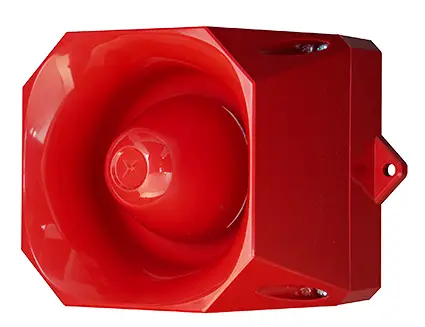
EATON Asserta 110 Fire Alarm Device 
Technical Data
| Specification | 24Vdc |
| Operation | Continuous |
| Operating Voltage Range | 18 – 30Vdc |
| Sound output @1m | See table overleaf |
| Current Consumption | See table overleaf |
| Tones | 44 – See table overleaf |
| Operating Temperature | -25°C to +70°C |
| Live Monitoring Method | Polarised Input |
| Construction | ABS FR Plastic Case |
| Ingress Protection | IP33C (IP66*) |
Note: Polar dispersion information available in the technical manual. (Ref:M04-005)
*Device not EN54 certified to IP66. Manufacturer’s declaration.
Essential Characteristics
| Fire Alarm Device – Sounder for indoor (type A) and outdoor (type B) use | |
| Essential Characteristics | |
| Harmonized Technical Specification: EN54-3:2001+A1:2002+A2:2006 | |
| Clause(s) | Performance |
| 4.2, 4.3, 5.2, 5.3 | Pass |
| 4.4, 4.5, 4.6, 5.4 | Pass |
| 5.5, 5.6, 5.7, 5.8, 5.9 | Pass |
| 5.8, 5.9, 5.10 | Pass |
| 5.11 | Pass |
| 5.12, 5.13, 5.14, 5.15 | Pass |
| 5.16 | Pass |
| 5.17 | Pass |
Installation
Knockout or drill required cable gland holes, and fix required cable glands.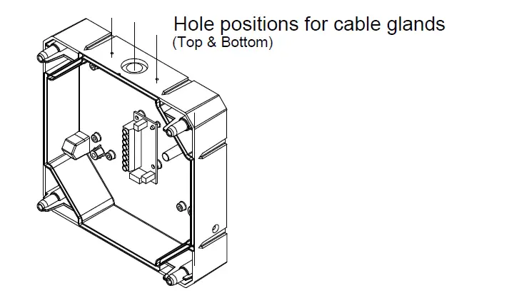
NOTE: Ensure that the IP integrity is maintained during gland fitting.
(Take care not to disturb the electronics while drilling. Remove PCB if required)
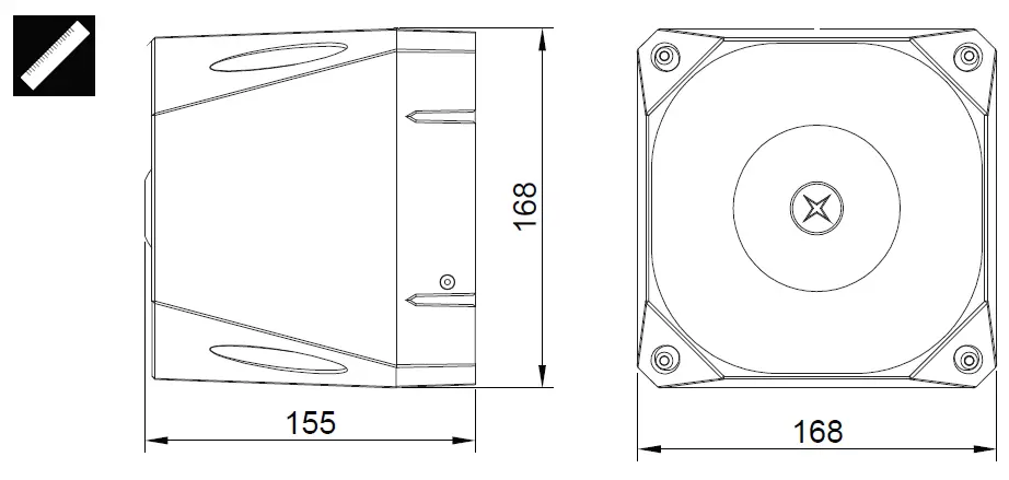
Fixing Details
Fix base to wall in 4 positions.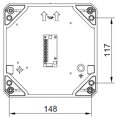
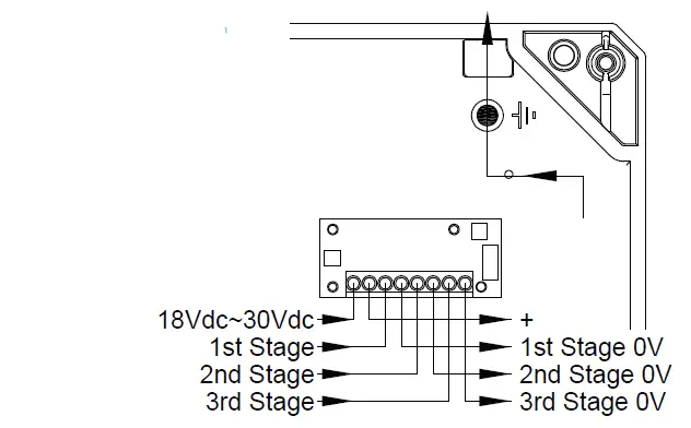
Connection Detail
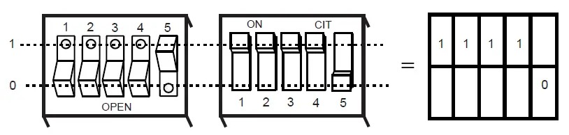
Sounder Settings
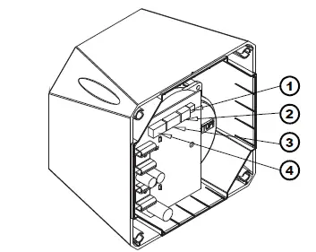
- Volume Control
 Turn dial clockwise to increase volume. (20dB Range)
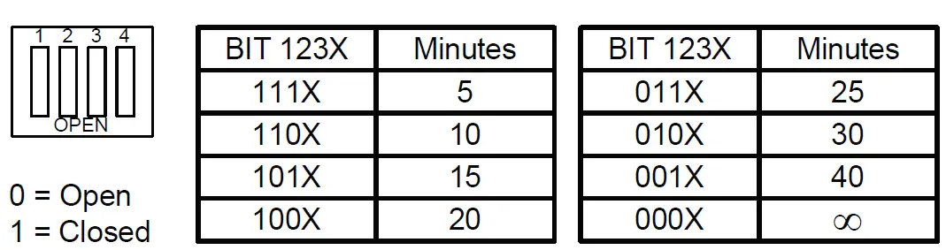
 - Switch 1 (Time out setting)

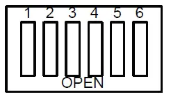
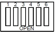
- Switch 2 (Stage1 tone selection)
See table overleaf.
- Switch 3 (Stage 2 tone selection)
See table overleaf. OPEN
(Stage 3 Tone is dependent on the setting of switch 2) - Switch positions

Sounder Assembly
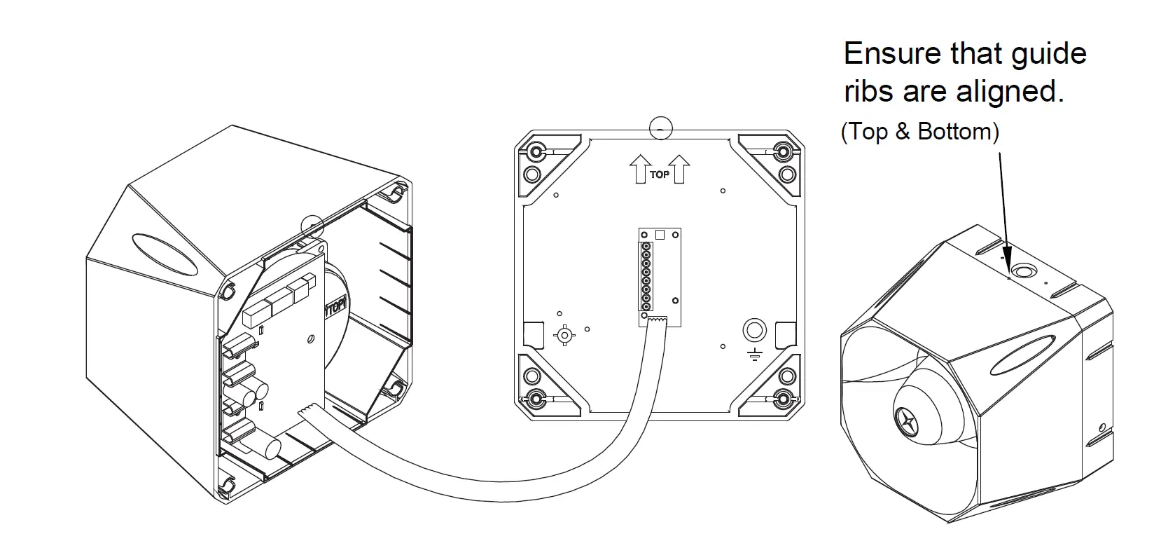
- Plug the 5 way ribbon cable into the base header.
- Ensure that the top indicator on the base is aligned with the top indicator on the sounder, and push the sounder onto the base.
- Secure the sounder to the base using the bolts provided.
Technical Data
Asserta Sounder Tones Table
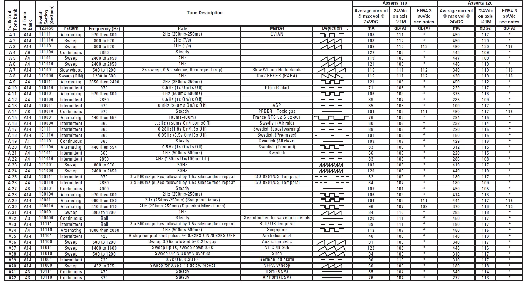
Note (a): Tones approved under the Construction ProductsRegulationfor Fire Alarm Applications, are shown in the column marked EN54-3.
Note (b): EN54-3 measurements shown reflect minimum expected SPL readings at Maximum Volume at the Loudest Point around the EN54-3 defined sounder axis.
Note (c): All other tone measurements reflect manufacturers’ data based on ‘on axis’ measurements, and are not verified by a Notified body.
Note (d): Detailed EN54-3 polar SPL measurements are available in the Product Manual for the appropriate sounder.
Note (e): All measurements were taken at 20˜C operating temperature.
Eaton Electrical Products Ltd.
Llantarnam Park
Cwmbran
NP44 3AW
Tel: +44 (0) 1633 628500
Fax: +44 (0) 1633 866346
Eaton
EMEA Headquarters Route de la Longeraie 7 1110 Morges, Switzerland Eaton.eu
TEL: +44 (0) 1302 321541 FAX: +44 (0) 1302 303220 [email protected] [email protected]
© 2021 Eaton
All Rights Reserved
Eaton is a registered trademark.
All trademarks are property
of their respective owners. www.eaton.com


