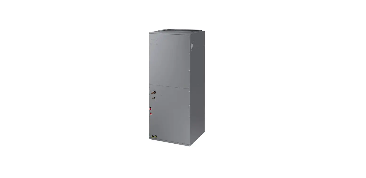
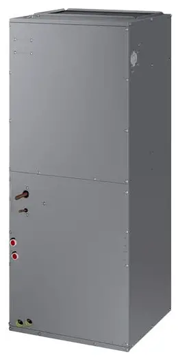
TRANE Supplementary Electric Heaters TEM4, TEM6, TEM8 and A4AH4 Air Handlers
ALL phases of this installation must comply with NATIONAL, STATE AND LOCAL CODES
Models:
BAYHTR1504BRKC BAYHTR1504LUGB BAYHTR1505BRKC BAYHTR1505LUGB BAYHTR1508BRKC BAYHTR1508LUGB BAYHTR1510BRKC BAYHTR1510LUGB BAYHTR1515BRKB BAYHTR1516BRKA BAYHTR1517BRKA BAYHTR1519BRKB BAYHTR1520BRKB BAYHTR1521BRKB BAYHTR1522BRKA BAYHTR1523BRKA BAYHTR1525BRKA BAYHTR3510LUGC BAYHTR3515LUGC BAYHTR3517LUGA
IMPORTANT — This Document is customer property and is to remain with this unit. Please return to service information pack upon completion of work.
WARNING: HAZARDOUS VOLTAGE – DISCONNECT POWER BEFORE SERVICING
GENERAL
This accessory electric heater is designed to provide power directly to the unit from the accessory heater’s power supply eliminating the need for additional circuits. The power and control wiring use a single polarized plug to connect the heater and the unit. See the Heater Data table on page 4 for the number of circuits required.
- Check the unit heater label to confirm that the selected Heater is approved for use with this unit in the installed configuration. For some heaters, a corresponding secondary nameplate label is included. Place the label within the heater data table on the air handler nameplate. This is shown in Figure 7.
- Check the components received for damage. Report any defects or shortages to the transportation company immediately.
- Be sure the power supply agrees with the listing shown on heater nameplate.
WARNING
THIS PRODUCT CONTAINS FIBERGLASS WOOL INSULATION! FIBERGLASS DUST AND CERAMIC FIBERS ARE BELIEVED BY THE STATE OF CALIFORNIA TO CAUSE CANCER THROUGH INHALATION. GLASSWOOL FIBERS MAY ALSO CAUSE RESPIRATORY, SKIN, OR EYE IRRITATION.
PRECAUTIONARY MEASURES
- Avoid breathing fiberglass dust
- Use a NIOSH approved dust/mist respirator
- Avoid contact with the skin or eyes. Wear long-sleeved, loose fitting clothing, gloves, and eye protection.
- Wash clothes separately from other clothing, rinse washer thoroughly.
- Operations, such as sawing, blowing, tear-out, and spraying may generate fiber concentrations requiring additional respiratory protection. Use the appropriate NIOSH approved respirator in these situations.
FIRST AID MEASURES
EYE CONTACT: FLUSH EYES WITH WATER TO REMOVE DUST. IF SYMPTOMS PERSIST, SEEK MEDICAL ATTENTION. SKIN CONTACT: WASH AFFECTED AREA GENTLY WITH SOAP AND WARM WATER AFTER HANDLING
NOTE: Illustrations may vary from the actual unit by cabinet and heater size.
INSTALLATION
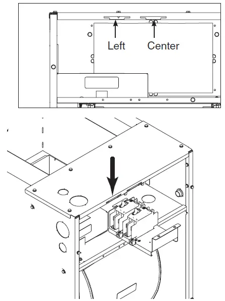
- Remove Blower Access panel.
- Locate heater knock-out plate at rear of control box.
- With tin snips, cut the four tabs located at the center points of the edges of knock-out plate.
- Discard knock-out plate.
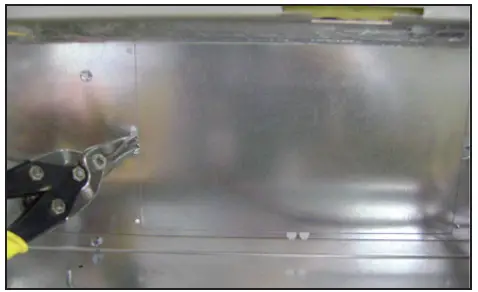
- Slide heater into opening.
- Secure heater to control box opening with four screws located at the corners of the mount plate. See Figure 2 for screw locations. (One not visible in photo)
IMPORTANT: The left side breaker mount location must be used for TEM8A0B24/30 air handlers, 25 kW heaters, and Single Power Entry Kits.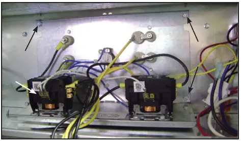
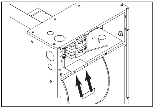
The center breaker mount location should be used for all other 4-20 kW heater installations. - Secure breaker/pull disconnect mount plate with two screws along the bottom of plate.
- Make all wiring connections per applicable field wiring diagrams. All installations must conform to national, state and local electrical codes.
- Connect the polarized harness plug to the polarized plug on the heater.
- Refer to the heater minimum airflow chart or the unit rating nameplate for the appropriate minimum blower speed tap to be used with the approved heater installed.
- Connect all field wiring per air handler installation guide.
Note: For LUG models, do not remove knockouts or insulation.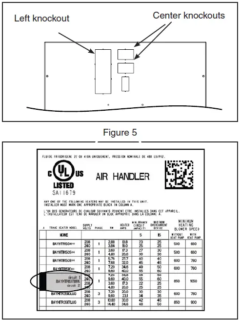
- Remove the appropriate breaker knock-out plates from Blower Access panel. Cut and remove insulation behind knock-out.
- IMPORTANT: Left knockout must be used for the following:
- ALL TEM8A0B24/30 air handlers
- All 25 kW heaters
- All TEM/A4AH4 air handlers installed with a Single Power Entry Kit ship with a Heater Breaker Seal Kit. (See Seal Kit Installer’s Guide for install instructions.)
Note: Follow the instructions in the Breaker Seal Kit 18-GJ85D1-1 (latest rev). The Breaker Seal Kit will ship with the TEM8A0B air handlers, 25 KW heaters and single power entry kits for TEM/A4AH4 air handlers. Center knockouts: Use for all other 4-20 kW heaters installations with all TEM/A4AH4 air handler (except TEM8A0B24/30).
- Install Blower Access panel ensuring alignment of breakers through access panel.
- On the unit nameplate, check off the heater that has been installed or apply the new secondary nameplate label within the heater data table on the air handler nameplate as shown in Figure 6.
Note: If using a heater in a TEM4/A4AH4 air handler, go to Step 18. - Cut insulated butt crimp terminal off of heater low voltage field wires (W1 – White, B/C – Blue)
- Strip 1/2″ insulation from the cut end for field thermostat wiring termination.
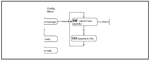
- For the TEM8 models, set the heater size in the Configuration Menu.
HEATER TABLES
IMPORTANT: The BAYHTR15** electric heat accessory may include up to a combination of four 60 amp circuit breakers to provide an electrical disconnect for service personnel that is intended to help protect internal electrical components in the event of a short circuit or ground fault. As designed, the circuit breakers supplied in the BAYHTR15** accessory DO NOT provide over current protection of the branch circuit. Therefore, the branch circuit(s) shall be sized and protected according to the unit nameplate.
| BAYHTR — HEATER DATA | |||||||
| Heater Model No | No. of Circuits/ Phases | 240 Volt | 208 Volt | ||||
| Capacity | Heater Amps per Circuit | Capacity | Heater Amps per Circuit | ||||
| kW | BTUH | kW | BTUH | ||||
| BAYHTR1504BRKC, BAYHTR1504LUGB | 1/1 | 3.84 | 13100 | 16.0 | 2.88 | 9800 | 13.8 |
| BAYHTR1505BRKC, BAYHTR1505LUGB | 1/1 | 4.8 | 16400 | 20.0 | 3.6 | 12300 | 17.3 |
| BAYHTR1508BRKC, BAYHTR1508LUGB | 1/1 | 7.68 | 26200 | 32.0 | 5.76 | 19700 | 27.7 |
| BAYHTR1510BRKC, BAYHTR1510LUGB | 1/1 | 9.6 | 32800 | 40.0 | 7.2 | 24600 | 34.6 |
| BAYHTR1515BRKB, BAYHTR1516BRKB, BAYHTR1517BRKA | 2/1 | 14.4 | 49200 | 40.0/20.0 | 10.8 | 36900 | 34.6/17.3 |
| BAYHTR1519BRKB, BAYHTR1520BRKB, BAYHTR1521BRKB, BAYHTR1522BRKA, BAYHTR1523BRKA | 2/1 | 19.2 | 65600 | 40.0/40.0 | 14.4 | 49200 | 34.6/34.6 |
| BAYHTR1525BRKA | 4/1 | 24.0 | 81900 | 25.0 each | 18.0 | 61600 | 21.6 each |
| BAYHTR3510LUGC | 1/3 | 9.6 | 32800 | 23.1 | 7.2 | 24600 | 20.0 |
| BAYHTR3515LUGC, BAYHTR3517LUGA | 1/3 | 14.4 | 49200 | 34.6 | 10.8 | 36900 | 30.0 |
| Note: For model specific electrical data, see the air handler Installer’s Guide or Submittal. Note: Heaters with two circuits are displayed as Circuit 1/Circuit 2 (Minimum Circuit Ampacity for Circuit 1 includes Blower Motor Amp) | |||||||
| TEM4/A4AH4 MINIMUM HEATER AIRFLOW CFM – HEATER MATRIX | ||||||||||||||||||||||||||||||||||||||||||||||||||||||||||||||||||||||||||||||||||||||||||||||||||||||||||||||||
|
Model No. | BAYHTR1504BRK* BAYHTR1504LUG* BAYHTR1505BRK* BAYHTR1505LUG* | BAYHTR1508BRK* BAYHTR1508LUG* BAYHTR1510BRK* BAYHTR1510LUG* BAYHTR3510LUG* |
BAYHTR1517BRK* |
BAYHTR1523BRK* |
BAYHTR1525BRK* |
BAYHTR3517LUG* | ||||||||||||||||||||||||||||||||||||||||||||||||||||||||||||||||||||||||||||||||||||||||||||||||||||||||||
TEM4A0B18S21SB*, A4AH4P18A1B060A* TEM4A0B24S21SB*,
A4AH4P24A1B060A* | L / M | L / M | – – | – – | – – | – – | ||||||||||||||||||||||||||||||||||||||||||||||||||||||||||||||||||||||||||||||||||||||||||||||||||||||||||
| TEM4A0B30S31SB*, A4AH4P30A1B060A* TEM4A0B36S31SB*, A4AH4P36A1B030A* | L / L | L / L | L / M | – – | – – | L / H | ||||||||||||||||||||||||||||||||||||||||||||||||||||||||||||||||||||||||||||||||||||||||||||||||||||||||||
| TEM4A0C37S31SB*, A4AH4P37A1C030A* | L / L | L / L | L / L | H / H | – – | L / L | ||||||||||||||||||||||||||||||||||||||||||||||||||||||||||||||||||||||||||||||||||||||||||||||||||||||||||
| TEM4A0C42S41SB*, A4AH4E42A1C030A* | L / L | L / L | L / L | L / M | – – | L / L | ||||||||||||||||||||||||||||||||||||||||||||||||||||||||||||||||||||||||||||||||||||||||||||||||||||||||||
| TEM4A0C48S41SB*, A4AH4E48A1C030A* TEM4A0C60S51SB*, A4AH4E60A1C030A* | L / L | L / L | L / L | L / L | L / L | L / L | ||||||||||||||||||||||||||||||||||||||||||||||||||||||||||||||||||||||||||||||||||||||||||||||||||||||||||
| TEM6 MINIMUM HEATER AIRFLOW CFM – HEATER MATRIX | ||||||||
|
Model No. | BAYHTR1504BRK* BAYHTR1504LUG* BAYHTR1505BRK* BAYHTR1505LUG* |
BAYHTR1508BRK* BAYHTR1508LUG* |
BAYHTR1510BRK* BAYHTR1510LUG* |
BAYHTR1517BRK* |
BAYHTR1523BRK* |
BAYHTR1525BRK* |
BAYHTR3510LUG* |
BAYHTR3517LUG* |
| TEM6A0B24H21SB* | 500/660 | 600/780 | 600/780 | 850/1050 | – – | – – | 600/780 | 850/900 |
| TEM6A0B30H21SB* | 500/660 | 600/780 | 600/780 | 850/1050 | – – | – – | 600/780 | 850/900 |
| TEM6A0C36H31SB* | 675/875 | 820/950 | 820/1000 | 820/1000 | 1140/1300 | – – | 820/875 | 950/1000 |
| TEM6A0C42H41SB* | 675/875 | 820/950 | 820/1000 | 820/1000 | 1140/1300 | – – | 820/875 | 950/1000 |
| TEM6A0C48H41SB* | 975/1200 | 975/1350 | 975/1350 | 975/1365 | 1300/1365 | 1505/1810 | 975/1300 | 1120/1365 |
| TEM6A0D48H41SB* | 975/1150 | 975/1150 | 975/1150 | 1125/1300 | 1125/1380 | 1345/1550 | 975/1150 | 1125/1300 |
| TEM6A0C60H51SB* | 975/1200 | 975/1350 | 975/1350 | 975/1365 | 1300/1365 | 1505/1810 | 975/1300 | 1120/1365 |
| TEM6A0D60H51SB* | 975/1150 | 975/1150 | 975/1150 | 1125/1300 | 1125/1380 | 1345/1550 | 975/1150 | 1125/1300 |
| TEM8 MINIMUM HEATER AIRFLOW CFM – HEATER MATRIX | ||||||||
| TEM8A0B24V21DB* | 600 / 650 | 700 / 850 | 700 / 850 | 850 / 1000 | – – | – – | 700 / 850 | 850 / 1000 |
| TEM8A0B30V21DB* | 600 / 650 | 700 / 850 | 700 / 850 | 850 / 1000 | – – | – – | 700 / 850 | 850 / 1000 |
| TEM8A0C36V31DB* | 675 / 675 | 900 / 950 | 900 / 950 | 900 / 950 | 1300 / 1500 | – – | 900 / 950 | 950 / 1050 |
| TEM8A0C42V41DB* | 675 / 675 | 900 / 950 | 900 / 950 | 900 / 950 | 1300 / 1500 | – – | 900 / 950 | 950 / 1050 |
| TEM8A0C48V41DB* | 800 / 900 | 1000 / 1200 | 1000 / 1350 | 1100 / 1400 | 1300 / 1430 | 1600 / 1850 | 1000 / 1200 | 1100 / 1400 |
| TEM8A0D48V41DB* | 800 / 900 | 1000 / 1200 | 1000 / 1200 | 1100 / 1400 | 1300 / 1400 | 1400 / 1600 | 1000 / 1200 | 1100 / 1400 |
| TEM8A0C60V51DB* | 800 / 900 | 1000 / 1200 | 1000 / 1350 | 1100 / 1400 | 1300 / 1430 | 1600 / 1850 | 1000 / 1200 | 1100 / 1400 |
| TEM8A0D60V51DB* | 800 / 900 | 1000 / 1200 | 1000 / 1200 | 1100 / 1400 | 1300 / 1400 | 1400 / 1600 | 1000 / 1200 | 1100 / 1400 |
HEATER STAGING
The TEM/A4AH4 air handler families do not stage air flow in correlation with heater element staging. The minimum heating air flow table is representative for any call for indoor heat.
| BAYHTR ELECTRIC HEAT STAGE MATRIX | |||||||||
|
Model No. | BAYHTR1504BRK* BAYHTR1504LUG* | BAYHTR1505BRK* BAYHTR1505LUG* | BAYHTR1508BRK* BAYHTR1508LUG* | BAYHTR1510BRK* BAYHTR1510LUG* | BAYHTR1517BRK* | BAYHTR1523BRK* | BAYHTR1525BRK* | BAYHTR3510LUG* | BAYHTR3517LUG* |
| Electric Heat Stages | 1 | 1 | 1 | 1 | 2 | 2 | 2 | 1 | 1 |
| Stage 1 Capacity (W1)(kW) | 3.84 | 4.8 | 7.68 | 9.6 | 9.6 | 9.6 | 12.0 | 9.6 | 14.4
|
| Stage 2 Capacity (W1+W2)(kW) | 3.84 | 4.8 | 7.68 | 9.6 | 14.4 | 19.2 | 24.0 | 9.6 | 14.4 |
About Trane and American Standard Heating and Air Conditioning Trane and American Standard create comfortable, energy efficient indoor environments for residential applications. For more information, please visit www.trane.com or www.americanstandardair.com The manufacturer has a policy of continuous data improvement and it reserves the right to change design and specifications without notice. We are committed to using environmentally conscious print practices. 18-HB22D1-14B-EN 07 Jun 2022
Supersedes 18-HB22D1-14A-EN (August 2020)


![Supplementary Electric Heaters For Jmm4&5 Wall-mount Air Handlers User Manual [bayhtrj505brkaa, Bayhtrj508brkaa & Bayhtrj510brkaa]](https://static-data1.manualsee.com/1/img/37/70750/2021/02/Supplementary-Electric-Heaters-Remove-the-upper-access-panel.jpg "Supplementary Electric Heaters For Jmm4&5 Wall-mount Air Handlers User Manual [bayhtrj505brkaa, Bayhtrj508brkaa & Bayhtrj510brkaa]")


