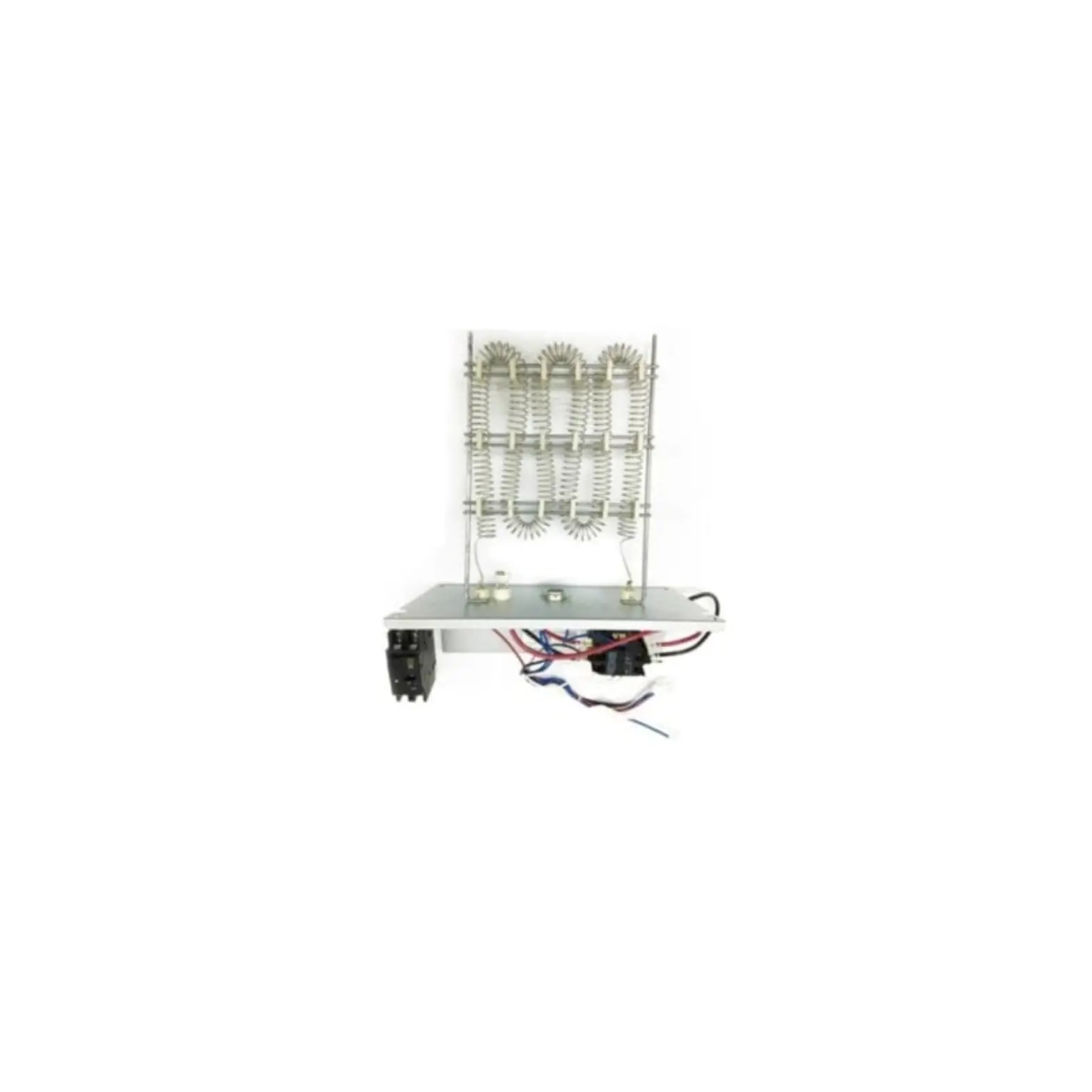
TRANE BAYHTR1605BRKA Supplementary Electric Heaters
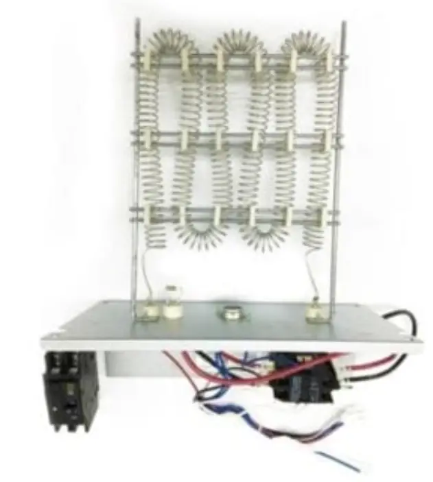
Models:
BAYHTR1605BRKA
BAYHTR161 OBRKA
BAYHTR161 SBRKA
BAYHTR1620BRKA
SAFETY
WARNING may cause personal death or serious injury.
CAUTION may lead to injury or structural damage under some conditions.
 WARNING
HAZARDOUS VOLTAGE!
DISCONNECT ALL ELECTRIC POWER INCLUDING REMOTE DISCONNECTS BEFORE SERVICING INSURE THAT ALL MOTOR CAPACITORS HAVE DISCHARGED STORED VOLTAGE. FAILURE TO DO THE ABOVE COULD RESULT IN DEATH OR SERIOUS INJURY.
WARNING
FIBERGLASS WOOL EXPOSURE!
REFER TO OWNER’S INFORMATION MANUAL PROVIDED WITH THIS UNIT FOR PROPER INSTALLATION, OPERATING AND MAINTENANCE INSTRUCTIONS.
DISTURBING THE INSULATION IN THIS PRODUCT DURING INSTALLATION, MAINTENANCE OR REPAIR WILL EXPOSE YOU TO AIRBORNE PARTICLES OF GLASS WOOL FIBERS AND CERAMIC FIBERS KNOWN TO THE STATE OF CALIFORNIA TO CAUSE CANCER THROUGH INHALATION. GLASS WOOL FIBERS COULD ALSO CAUSE RESPIRATORY, SKIN OR EYE IRRITATION.
WARNING
FIRE HAZARD!
WITH HEAT PUMP INSTALLATIONS, SOME ELECTRIC HEATERS ARE POSITION SENSITIVE. USE ONLY APPROVED HEATER TO UNIT COMBINATIONS PER NAMEPLATE AND SET BLOWER AIRFLOW SPEED PER NAMEPLATE INSTRUCTIONS.
WHEN HEATERS COME SUPPLIED WITH CIRCUIT BR EAKERS, USE 240/208 VOLT SUPPLY POWER WITH 120 VOLTS (NOMINAL) TO GROUND.
FAILURE TO FOLLOW THE ABOVE COULD RESULT IN DEATH, SERIOUS INJURY OR EQUIPMENT DAMAGE.
ATTENTION INSTALLING PERSONNEL
Prior to installation, thoroughly familiarize yourself with this Installation Manual. Observe all safety warnings. During installation or repair, caution is to be observed It is your responsibility to install the product safely and to educate the customer on its safe use.
Electrical Data
Table 1. Electrical data
| Model Number | Voltage-Phase-Hz | Power Supply Wiring Gauge | Motor HP | Motor Steps | Minimum Circuit AMPS | Fuse (A) |
| E4AH5E24A 1J30A | 208/230-1Ph-60Hz | 14 | 1/3 |
5 | 3.0 | 15 |
| E4AH5E36A1J30A | 1/2 | 5.2 | ||||
| E4AH5E48A 1K30A | 3/4 | 7.5 | ||||
| E4AH5E60A 1K30A | 3/4 | 7.5 |
Electric Heat Data
Table 2. Electric heat data
| Kit Model | Model Number | Electric Heat (kW) | MIN. Circuit Ampacity | MAX. Fuse or Breaker ( HA C R)Ampacity | Fan speed | ||||||
| 208 | 230 | 208 | 230 | 1 | 2 | 3 | 4 | 5 | |||
| BAYHTR1605BRKA | E4AH5E 24A1J30A | 5 | 23 | 25 | 25 | 30 | X | X | • | • | • |
| B AYHTR1610BR KA | 10 | 45 | 50 | 50 | 60 | X | X | • | • | • | |
| BAYHTR1605BRKA | E4AH5E 36A1J30A | 5 | 23 | 25 | 25 | 30 | X | X | • | • | • |
| BAYHTR 16 10BRKA | 10 | 45 | 50 | 50 | 60 | X | X | • | • | • | |
| BAYHTR1615BRKA | 5+10 | 23+45 | 25+50 | 50+25 | 60+30 | X | X | • | • | • | |
| BAYHTR1605BRKA | E4AH5E 48A1K30A | 5 | 23 | 25 | 25 | 30 | X | X | • | • | • |
| BAYHTR1610BRKA | 10 | 45 | 50 | 50 | 60 | X | X | • | • | • | |
| BAYHTR 1615BRKA | 5+10 | 2 3 +45 | 25+50 | 50+25 | 60+30 | X | X | • | • | • | |
| BAYHTR1620BRKA | 10 +10 | 4 5+45 | 50+50 | 50+50 | 60+60 | X | X | X | • | • | |
| BAYHTR 160 5BRKA | E4AH5E 60A1K30A | 5 | 23 | 25 | 25 | 30 | X | X | • | • | • |
| BAYHTR1610BRKA | 10 | 45 | 50 | 50 | 60 | X | X | • | • | • | |
| BAYH TR1615BRKA | 5+10 | 23+45 | 25+50 | 50+25 | 60+30 | X | X | • | • | • | |
| BAYHTR1620BRKA | 10+10 | 45+45 | 50+50 | 50+50 | 60+60 | X | X | X | • | • | |
*MCA and Max Fuse Ampacity contains the motor amps.
Electric heat kits are suitable for air handler multiple position installation.
• means available X means unavailable
Safety Cautions All electric work must be performed by qualified personnel.
BAYHTR16** series is designed and approved to be installed in the AMERISTAR or RUNTRU series air handlers.
- Check the BA YHTR 16** label to confirm BA YHTR 16** size based on room load under lowest ambient temperature.
- Inspect all heating elements and whether heater element wires. Contact local distributor immediately if there is any occurred damage.
Warning
- Disconnect all external power supplies before performing installation and servicing. Turn off accessory heater power switch if applicable. Failure to do so may cause serious injury.
- BA YHTR16** must be properly grounded and use copper supply wires.
- Make sure to follow national electric code and local regulations.
- When installing it in an enclosed area such as a garage, heater elements should have a minimum clearance of 18″ from the floor to insure the proper ventilation.
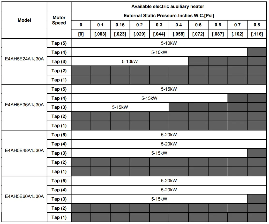
Available electric auxiliary heater
When unit is installed with electric auxiliary heater, the fan speed selection must meet the following static pressure requirements, and the gray boxes part is not allowed to use electric auxiliary heating.
INSTALLATION INSTRUCTIONS “BAYHTR16**”
Electric Heater Kits For use in Air Handlers ATTENTION INSTALLING PERSONNEL
Prior to installation, thoroughly familiarize yourself with this installation manual. Observe all safety warnings. During installation or repair, caution is to be observed. It is your responsibility to install the product safely and to educate the customer on its safe use.
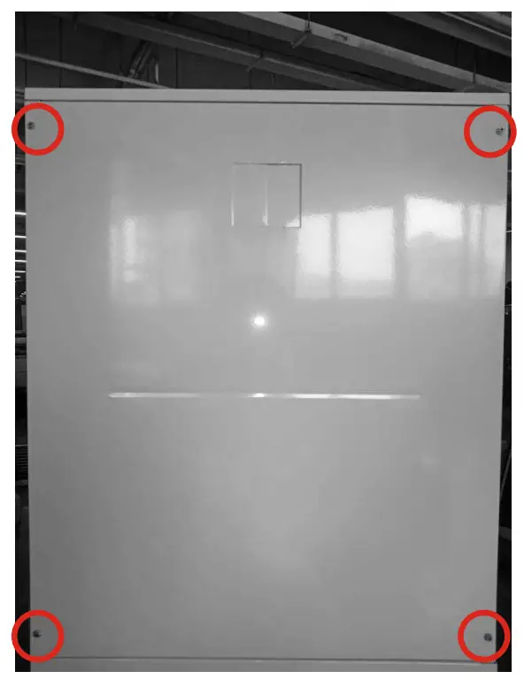
STEP 1. Unfasten 4 screws to take away the blower access panel of the air handler.
STEP 2.Remove the cover plate from the air handler.
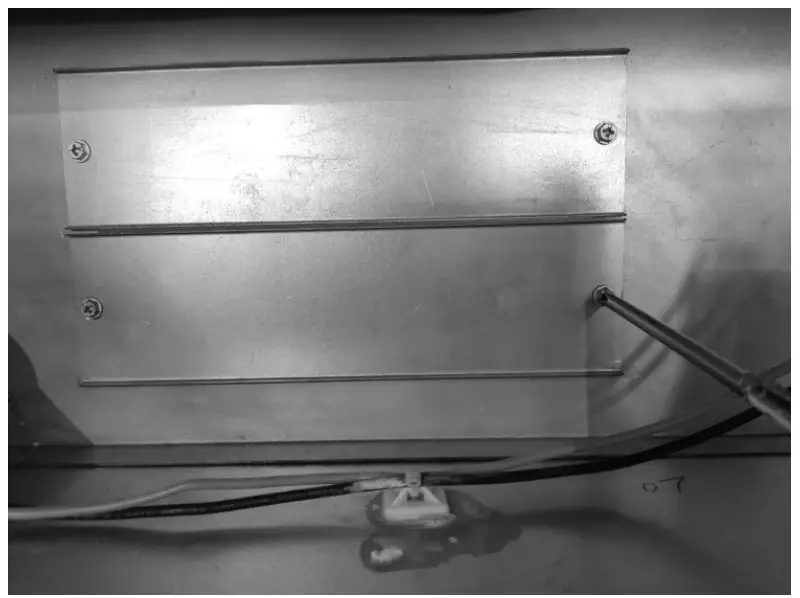
STEP 3.Slide the heater kit into the slot and secure element plate with previously removed screws.
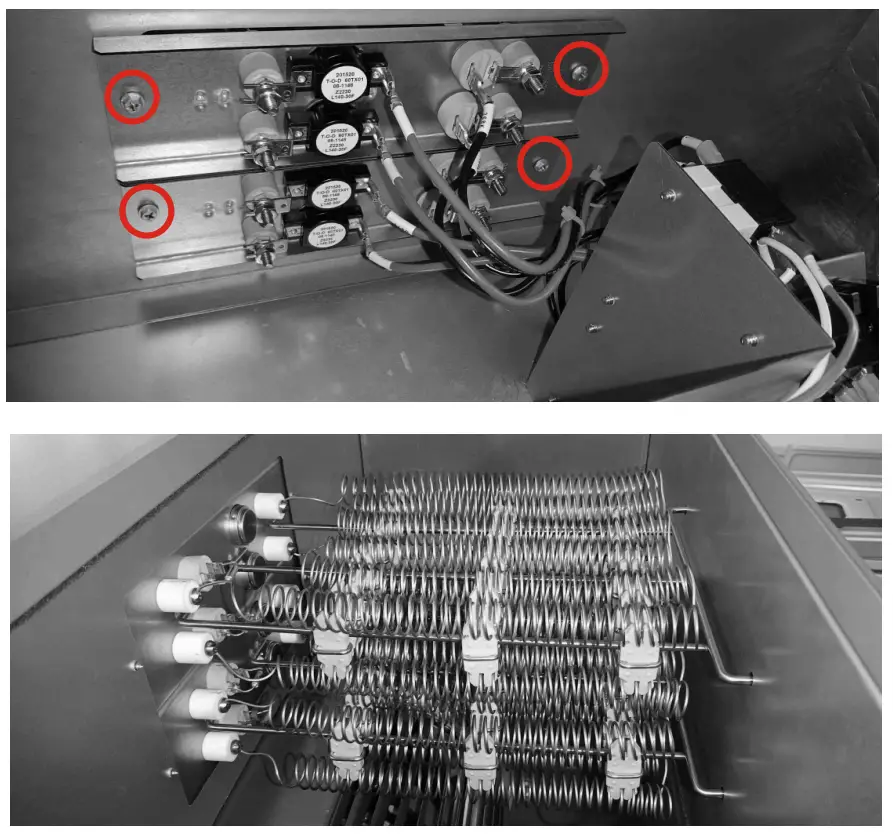
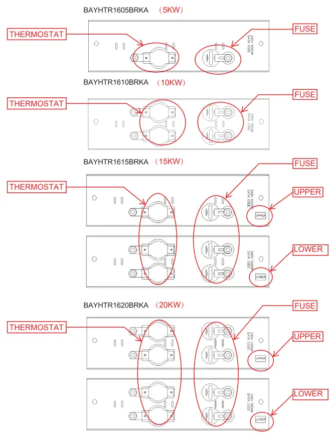
When sliding the heater kit into the slot ensure that it is installed in the correct orientation described below. Thermostat will be on the left hand side and the fuse will be on the right hand side.
When two elements are being used ensure that “UPPER” and “LOWER” elements are installed in the correct slots and orientations.
STEP 4. Align the attachment clip and the hole and fasten the loose wires by using wire tie
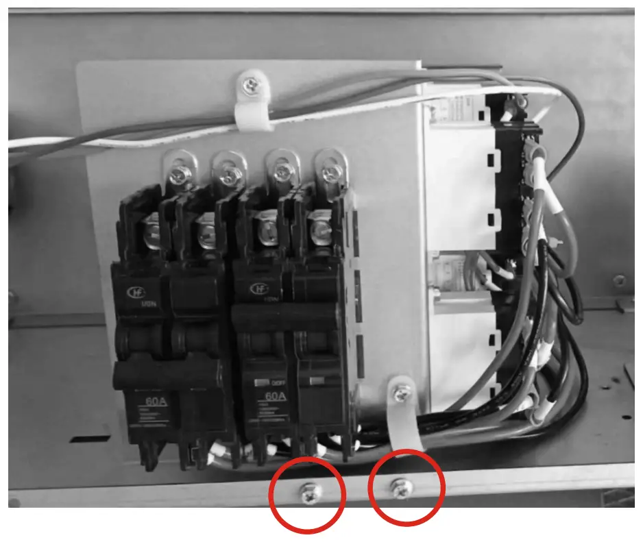
STEP 5. Install the circuit breaker into the mounting rail, break out appropriate area of the plastic circuit breaker cover on the access panel of the air handler.
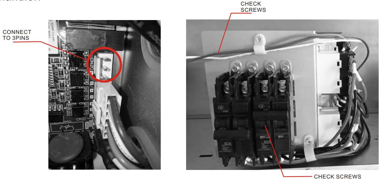
WARNING
FIRE, ELECTRICAL SHOCK, HAZARD
After connecting all wires, check all screws of breaker and make sure all screws are properly tight.
Failure to do so will result in breaker malfunction, fire, death, personal injury and properly damage.
NOTE:
- When indoor control board receives W1/W2 signal, electric heater will be energized and indoor blower will be turned on.
- When W1/W2 signal is off, indoor blower will be turned off.
- Blower motor runs when “G” is energized, and off when “G” is de-energized.
Figure 4-3 Wiring diagram for 5KW electric heat
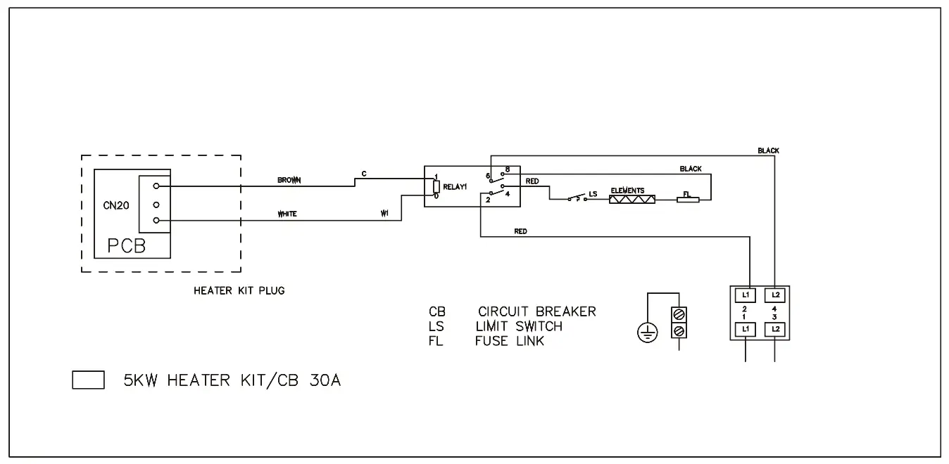
Figure 4-4 Wiring diagram for 10KW electric heat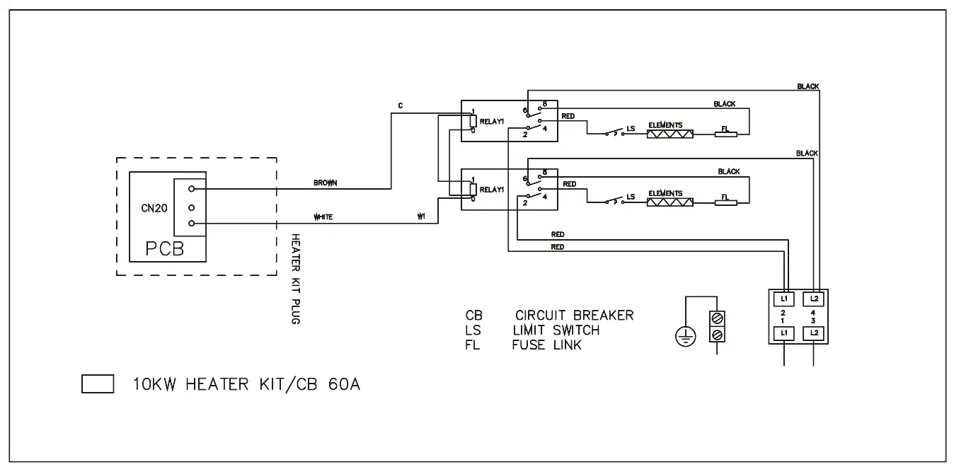
Figure 4-5 Wiring diagram for 15KW electric heat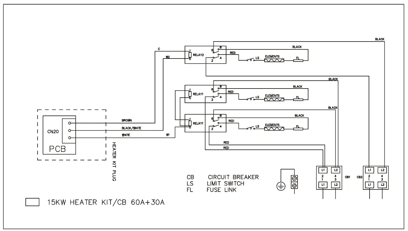
Figure 4- Wiring diagram for 20KW electric heat
About Trane and American Standard Heating and Air Conditioning
Trane and American Standard create comfortable, energy efficient indoor environments for residential applications. For more information, please visit www.trane.com or www.americanstandardair.com.
The manufacturer has a policy of continuous data improvement and it reserves the right to change design and specifications without notice. We are committed to using environmentally conscious print practices.


![Supplementary Electric Heaters For Jmm4&5 Wall-mount Air Handlers User Manual [bayhtrj505brkaa, Bayhtrj508brkaa & Bayhtrj510brkaa]](https://static-data1.manualsee.com/1/img/37/70750/2021/02/Supplementary-Electric-Heaters-Remove-the-upper-access-panel.jpg "Supplementary Electric Heaters For Jmm4&5 Wall-mount Air Handlers User Manual [bayhtrj505brkaa, Bayhtrj508brkaa & Bayhtrj510brkaa]")


