Circutor RECmax LPd Earth Leakage Circuit Breaker User Guide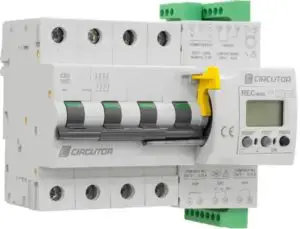
IMPORTANT!
![]() The device must be disconnected from its power supply sources (power supply and measurement) before undertaking any installation, repair or handling operations on the device’s connections. Contact the after-sales service if you suspect that there is an operational fault in the device. The device has been designed for easy replacement in case of malfunction.
The device must be disconnected from its power supply sources (power supply and measurement) before undertaking any installation, repair or handling operations on the device’s connections. Contact the after-sales service if you suspect that there is an operational fault in the device. The device has been designed for easy replacement in case of malfunction.
![]() The manufacturer of the device is not responsible for any damage resulting from failure by the user or installer to heed the warnings and/or recommendations set out in this manual, nor for damage resulting from the use of non-original products or accessories or those made by other manufacturers.
The manufacturer of the device is not responsible for any damage resulting from failure by the user or installer to heed the warnings and/or recommendations set out in this manual, nor for damage resulting from the use of non-original products or accessories or those made by other manufacturers.
DESCRIPTION
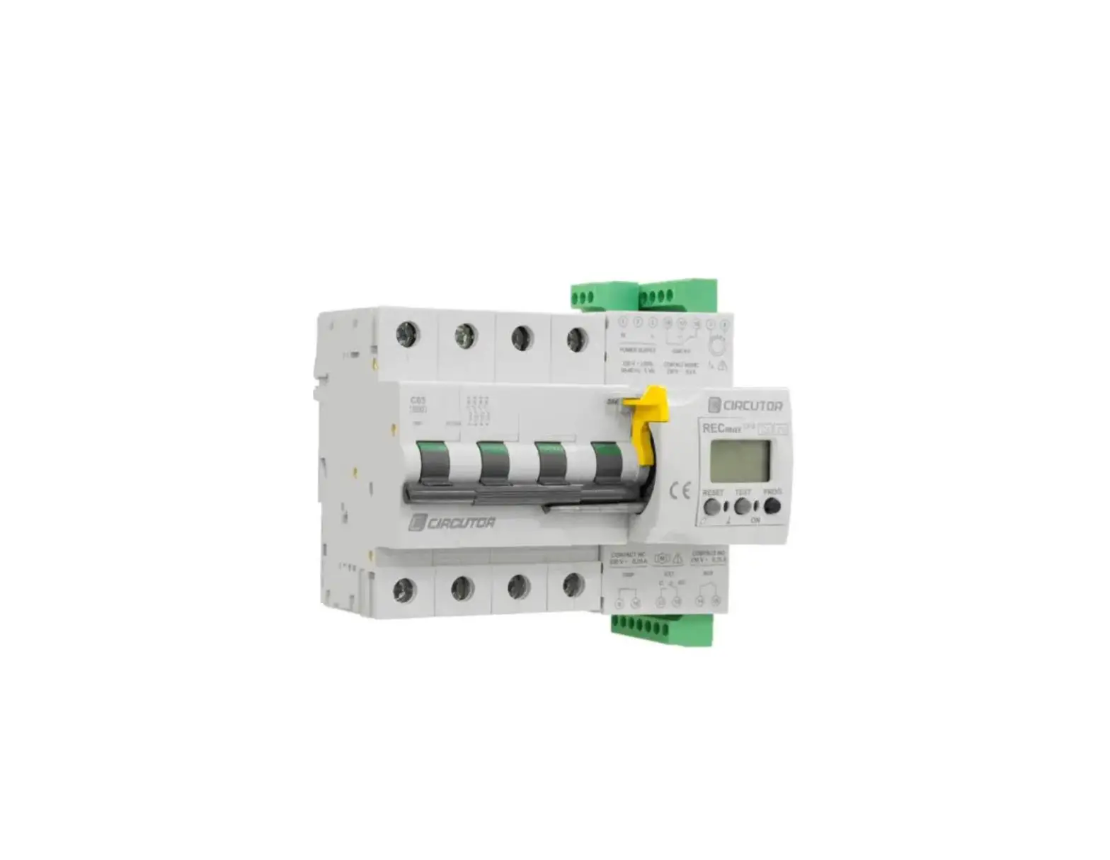
El RECmax LPd is a protection device with cut-off capacity that includes a circuit breaker for over- current protection and ultra-immunised earth leakage protection. It has a programmable controller with a display, which measures leakage currents (earth leakage protection), and controls the disconnection or re-closing of the main circuit breaker through a motor, which drives the main switch mechanism. The leakage current measurement, I∆, needs an external earth leakage transformer, which is supplied separately.
The assembly is regularly used in electrical, single-phase and three-phase installations that require high continuity of the electric supply. It has inputs/outputs which provide information and control on the status of the electrical installation which protects.
INSTALLATION
RECmax LPd must be installed inside an electric panel or enclosure and mounted on a DIN rail.
It has LED indicators signalling that voltage is present. Even though these LED are not on, this does not relieve the user from verifying that the unit is disconnected from all power supply sources.
![]() IMPORTANT!
IMPORTANT!
Take into account that when the device is connected, the terminals may be hazardous to the touch, and opening the covers or removing elements may provide access to parts that are dangerous to the touch. Do not use the device until it is fully installed.
The device’s auxiliary supply must be protected with fuses or protection elements appropriate for the power supply range and consumption. Preferably the protection should consist of a small circuit breaker allowing the disconnection of the unit from the power supply in case of servicing.
STATUS OF UNIT IN NORMAL OPERATING CONDITIONS
In normal operating conditions (no trip), the unit has the following status:
- Main switch closed. Switch lever up.
- Motor lever 1 down.
- Green LED ON and red LED OFF. 3
- Green LED illumination, fixed screen. 3
- TRIP output, terminals 9-10. NC contact
- AUX output, terminals 14-15. Closed contact (opens if the auxiliary power supply fails).
- ON/OFF, change over contact
The unit can be manually disconnected by lowering the switch lever and moving the yellow lock 2 towards the main poles
In this way, the unit will be disconnected from the auxiliary power supply and the possibility of an accidental re-closing is overridden.
![]() In case of manual circuit breaker opening the mechanical blocking system should be locked at the same time to prevent any accidental re-closing while servicing the installation. In case, of manual disconnection and locking, be aware that the auxiliary power supply of the RECmaxLpd can be connected and there is a danger of electric shock, when servicing the device, even if the green LED does not light. Therefore, maximum care must be taken to touch the RECmaxLpd terminals.
In case of manual circuit breaker opening the mechanical blocking system should be locked at the same time to prevent any accidental re-closing while servicing the installation. In case, of manual disconnection and locking, be aware that the auxiliary power supply of the RECmaxLpd can be connected and there is a danger of electric shock, when servicing the device, even if the green LED does not light. Therefore, maximum care must be taken to touch the RECmaxLpd terminals.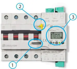
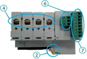
Components
Components | |
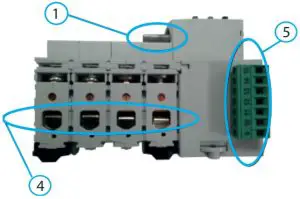
| 1 | The lever is used to re-close the main switch. The default position of the lever is down. In case of a re-closing, the lever is raised by a motorized driver, which connects the main switch. After the re-closing, the motor drives the lever back to the down position. |
| 2 | The system consists of a mechanical lock avoiding the reconnection of the main switch, thus overriding the automatic re-closing option Note: The locking lever can be mechanically locked. |
| 3 | Front of motorized controller Display, LED, Pulsadores / push-button |
| 4 | Circuit breaker power contacts. |
| 5 | Bottom plug-in terminals set EXT (12,13) Isolated input for external trip/rearm. Activated by pulse signal (200 ms). TRIP (9,10): NC output indicating that re-closing attempts have been exhausted. AUX (14,15): NO output indicating that the unit is not going to re-close due to a fault. |
| 6 | Top plug-in terminals set ON/OFF (16,17,18) Circuit breaker status. |
| 7 | Top plug-in terminals set I∆ (7,8): Isolated earth leakage current measurement transformer signal input. Power supply (1,3) |
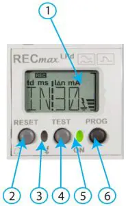
Indicators
Indicators | |
1 | Green display backlight |
2 | RESET push-button |
3 | Red LED (1) |
4 | TEST push-button |
| 5 | Green LED (1) Denotes normal operation |
6 | PROG push-button SETUP Mechanically locked |
If the green and red LED are blinking, indicates some type of malfunction,
contact the assistance service.
Technical features
| Power supply | ||||
| Rated voltage | 230 V ~ ± 30% | |||
| Frequency | 50 / 60 Hz | |||
| Power | 5VA | |||
| Uimp | 4kV | |||
| Installation category | CAT III 300 V | |||
| Sensitivity, I∆n | 30 mA | |||
| Trip delay (IEC 60947-2-M) | Instantaneous | |||
| CIRCUTOR compatible types | WG / WGS / WGC | |||
| Internal diameters (mm.) | 20-25-30-35 | |||
| Nominal current, In (4 poles) | 63 A | |||
| Trip current, I∆n | 30 mA | |||
| Maximum current, Imax | 378 A | |||
| All the live conductors feeding the load to be protected must pass through the core of the earth leakage transformer. The earth protection conductor must never pass through the earth leakage transformer. | ||||
| Current, In | 6, 10, 16, 20, 25, 32, 40, 50, 63 A ~ | |||
| Rated voltage, Un | 240 / 415 V~ | |||
| Magnetic trip curves | C / D | |||
| Cross-section | Flexible cable | Rigid cable | ||
| 25 mm2 | 35 mm2 | |||
| Number of poles | 2 / 4 | |||
| Residual earth leakage current | 0.851 I∆n | |||
| Breaking capacity (EN 60898) | Poles | Voltage | Ics | |
| 1 – 4 | 230 / 400 V | 6 kA | ||
| Breaking capacity (EN 60947-2) | Poles | Voltage | Icu / Ics | |
| 2 | < 125 V | 30 kA | ||
|
Breaking capacity (EN 60947-2) ~ | Poles | Voltage | Icu | |
| 2 | 127 V | 30 kA | ||
| 240 V | 20 kA | |||
| 415 V | 10 kA | |||
| 4 | 240 V | 20 kA | ||
| 415 V | 10 kA | |||
| Successive earth leakage attempts | 10 | |||
| Successive circuit breaker attempts | 2 | |||
| Timing between successive attempts | 3 min. | |||
| Counter attempts reset time, after last re-closing | 30 min. | |||
| After exhausting the successive re-closing attempts unsuccessfully, the unit is definitively switched OFF. Reset from this status must be either by manual RESET or by remote reset through input EXT | ||||
| EXT input, terminals 12-13 | Libre de tensión / Voltage-free | |||
| AUX output, terminals 14-15 (1) | 0.25 A – 230 V | |||
| TRIP output, terminals 9-10 (1) | 0.25 A – 230 V | |||
| ON/OFF output, terminals 16-17-18 (1) | 0.5 A – 230 V | |||
| Frequency | 50 / 60 Hz | |||
| (1) Installation category | AUX, TRIP : CAT II 300 V – ON/OFF: CAT III 300 V | |||
| Operating temperature | -20ºC… +70ºC | |||
| Relative humidity (non-condensing) | 5 … 95% | |||
| Maximum altitude | 2000 m | |||
| Protection degree | IP20 – IP41 ( tras cuadro / cabinet panel mounted ) | |||
| Self-extinguishing capability | V0 (UL) | |||
| Screws | M3 | |||
| Insertion force per pole | max 3N | |||
| Withdrawal force per pole | min 5N | |||
| Recommended torque | 0.5 / 0.6 Nm | |||
| Length of stripped insertion cable | 6 – 7.5 mm | |||
| Maximum cross-section | Cable rígido / Rigid cable | Cable flexible / Flexible cable | ||
| 0.05 – 2.5 mm2 | 0.05 – 1.5 mm2 | |||
| Attachment (EN50022) | Carril / rail DIN 46277 | |||
| Dimensions | Monofásico / Single-phase | Trfásico / Three-phase | ||
| 4.5 módulos / modules | 6.5 modulos / modules | |||
| Weight | 550 gr | 800 gr | ||
| Enclousure | PC + FV | |||
| Standars | ||||
| IEC 60755 , IEC 60947-2 | ||||
Conections
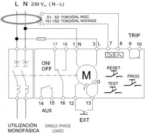
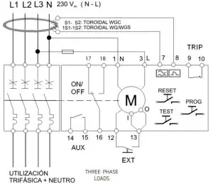
![]() The N-L auxiliary power supply may be external to the installation to be protected, but in no case it must be connected downstream from the main switch.
The N-L auxiliary power supply may be external to the installation to be protected, but in no case it must be connected downstream from the main switch.![]() Make sure that the Neutral conductor connection is made as indicated in the connection diagrams in this guide.
Make sure that the Neutral conductor connection is made as indicated in the connection diagrams in this guide.
Dimensions
Three-phase installation – 4 poles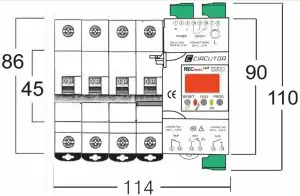
Single-phase installation – 2 poles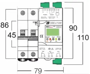
Terminal connections designations | |
1, 3 | Power supply |
| 7, 8 | Measurement input |
9 | TRIP output (Common) |
10 | TRIP output (NC) |
| 12,13 | Remote control input EXT |
14 | AUX output (Common) |
| 15 | AUX output (NO) |
16 | ON/OFF output (Common) |
| 17 | ON/OFF output (NC) |
| 18 | ON/OFF output (NO) |
Technical service
CIRCUTOR SAT: 902 449 459 (SPAIN) / (+34) 937 452 919 (out of Spain)
Vial Sant Jordi, s/n
08232 – Viladecavalls (Barcelona)
Tel: (+34) 937 452 900
Fax: (+34) 937 452 914
e-mail : [email protected]
This manual is a RECmax LPd installation guide. For further information, please download the full manual from the CIRCUTOR web site: www.circutor.com


