![]()
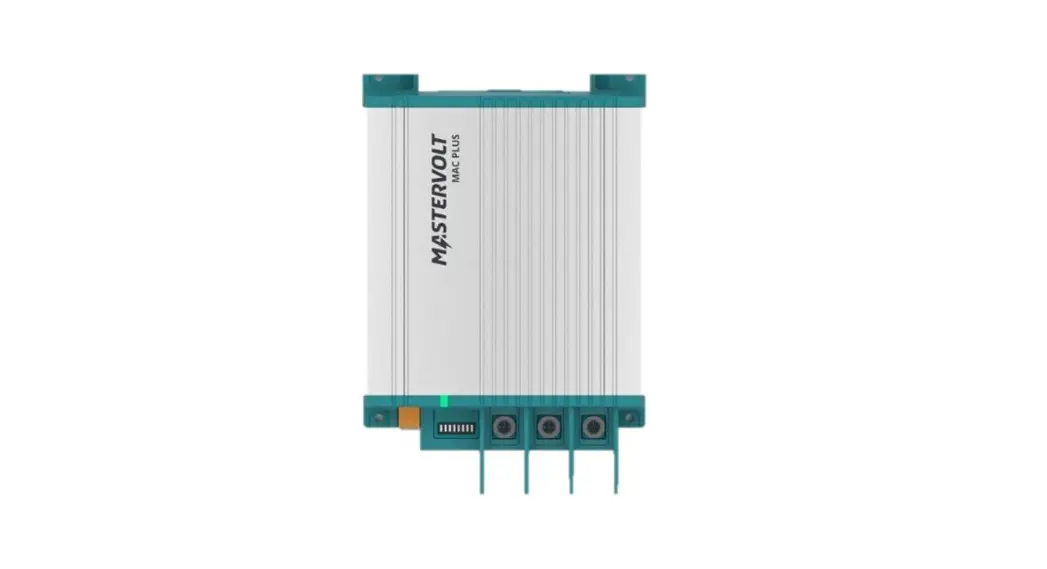
Mac Plus
DC-DC CHARGER
12/12-50, 12/24-30, 24/12-50, 24/24-30
USER AND INSTALLATION MANUAL
For the latest version of this manual, visit our website: www.mastervolt.comNFIGURATION DIP
Safety instructions
This chapter describes important safety and operating instructions for use of a Mac Plus in residential, vehicle (RV) and marine applications. www.mastervolt.com
Warnings and symbols Safety instructions and warnings are marked in this manual and on the product by the following pictograms:
![]() CAUTION!
CAUTION!
Special information, commands and prohibitions in order to prevent damage.
![]() WARNING!
WARNING!
WARNING refers to possible injury to the user or installer or significant material damage to the Mac Plus if the installer / user does not (carefully) follow the stated procedures.
General
- Before using the Mac Plus, read all instructions and cautionary markings on the Mac Plus, the batteries, and all appropriate sections of the manual.
- To reduce the risk of electric shock Do not expose the Mac Plus to rain, snow, spray, moisture, excessive pollution and condensing circumstances. To reduce risk of fire hazard, do not cover or obstruct the ventilation openings. Do not install the Mac Plus in a poorly ventilated room, this may result in overheating.
- Use of an attachment or spare part not recommended or sold by ASG may result in a risk of fire, electric shock, or injury to persons.
- The Mac Plus is designed to be permanently connected to a DC electrical system. Installation of, and work on the Mac Plus, may be carried out only by a qualified, authorized and trained technician or electrician, consistent with the locally applicable standards and regulations.
- Make sure that all wiring is properly installed and in good electrical condition; and that wire size is large enough for DC ampere rating of the Mac Plus. Check the wiring on a regular base, at least once a year. Do not use the Mac Plus when the wiring is undersized or damaged and replace the wiring immediately.
- Do not operate Mac Plus if it has received a sharp blow, been dropped, or otherwise damaged in any way; take it to a qualified service technician.
- Except for the connection compartment, the Mac Plus may not be opened or disassembled. There are no serviceable parts inside the cabinet. Take it to a qualified, authorized, and trained Mac Plus service technician when service or repair is required. Incorrect reassembly may result in a risk of electric shock or fire.
- To reduce risk of electric shock, disconnect the Mac Plus from the DC electrical system before attempting any maintenance or cleaning. Turning off controls will not reduce this risk.
- The Mac Plus may not be used by children or by those who cannot read and understand the manual if they are not supervised by a responsible person who can guarantee that the charger is being used in a safe manner. Keep the charger away from children.
- Short circuiting or reversing polarity will lead to serious damage to batteries, Mac Plus, wiring as well as accessories. Fuses cannot prevent damage caused by reversed polarity and the warranty will be void.
- In case of fire, you must use the fire extinguisher which is appropriate for electrical equipment.
- If applied in a marine application in the United States, external connections to the Mac Plus shall comply with the United States Coast Guard Electrical Regulations (33CFR183, Sub part I).
Explosive gases
- WARNING RISK OF EXPLOSIVE GASES. WORKING IN VICINITY OF A LEAD-ACID BATTERY IS DANGEROUS. BATTERIES GENERATE EXPLOSIVE GASES DURING NORMAL BATTERY OPERATION. FOR THIS REASON, IT IS OF UTMOST IMPORTANCE THAT EACH TIME BEFORE USING THE Mac Plus, YOU READ THIS MANUAL AND FOLLOW THE INSTRUCTIONS EXACTLY.
- To reduce risk of battery explosion, follow these instructions and those published by battery manufacturer and manufacturer of any equipment you intend to use in the vicinity of the battery. Review cautionary marking on these products.
- DANGER: To reduce the risk of explosion Never use the Mac Plus in situations where there is danger of gas or dust explosion or area in which ignition-protected equipment is required.
Warnings regarding the use of batteries
- Someone should be within range of your voice or close enough to come to your aid when you work near a battery.
- Have plenty of fresh water and soap nearby in case battery acid contacts skin, clothing, or eyes.
- Wear complete eye protection and clothing protection. Avoid touching eyes while working near battery.
- If battery acid contacts skin or clothing, wash immediately with soap and water. If acid enters eye, immediately flood eye with running cold water for at least 10 minutes and get medical attention immediately.
- NEVER smoke or allow a spark or flame in vicinity of battery or engine.
- Do not short circuit batteries, as this may result in explosion and fire hazard! Be extra cautious to reduce risk of dropping a metal tool onto battery. It might spark or short-circuit battery or other electrical part that may cause explosion.
- Remove personal metal items such as rings, bracelets, necklaces, and watches when working with a battery. A battery can produce a short-circuit current high enough to weld a ring or the like to metal, causing a severe burn.
- Only use Mac Plus for charging a LEAD-ACID or Mastervolt Li-Ion batteries and the supply of loads attached to these batteries, in permanent systems. Do not use Mac Plus for charging drycell batteries that are commonly used with home appliances. These batteries may burst and cause injury to persons and damage to property.
- NEVER charge a frozen battery.
- Excessive battery discharge and/or high charging voltages can cause serious damage to batteries. Do not exceed the recommended limits of discharge level of your batteries.
- If it is necessary to remove a battery, always remove grounded terminal from battery first. Make sure all accessories are off, so as not to cause an arc.
- Be sure that the area around battery is well ventilated while battery is being charged. Refer to the recommendations of the battery manufacturer.
- Batteries are heavy! It may become a projectile if it is involved in an accident! Ensure adequate and sure mounting and always use suitable handling equipment for transportation.
Warning regarding life support applications
Do not use the Mac Plus for applications in any medical equipment intended for use as a component of a life support system. For this type of use a specific written agreement between the customer and ASG is required.
General information
Liability ASG can accept no liability for:
- Consequential damage resulting from the use of the Mac Plus.
- Possible errors in the included manual and the consequences of these.
- Use that is inconsistent with the purpose of the product.
Warranty
The Mastervolt product warranty covers the Mac Plus for the first two years after the purchase date, on the condition that the product is installed and used according to the instructions in this manual. Installation or use that do not comply with these instructions may result in under performance, damage or failure of the product and may void this warranty. The warranty is limited to the cost of repair and/or replacement of the product. Costs of labor or shipping are not covered by this warranty.
Disclaimer
Our products are subject to continual development and improvement. Therefore, additions or modifications to the products may cause changes to the technical data and functional specifications. No rights can be derived from this document. Please consult our most current Terms & Conditions of Sale.
Identification label
Important technical information required for service, maintenance & secondary delivery of parts can be derived from the identification label.
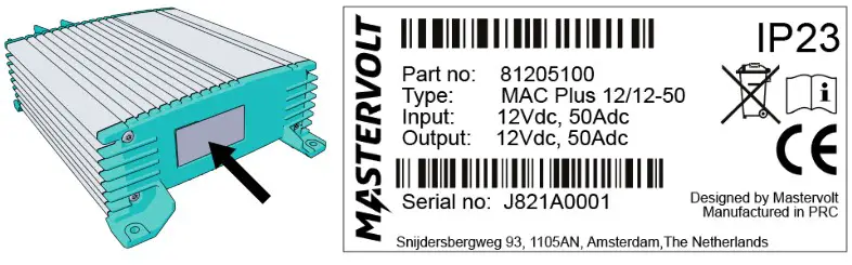
![]() CAUTION!
CAUTION!
Never remove the identification label. This will void the warranty.
Correct disposal of this product
![]() This product is designed and manufactured with high quality materials and components, which can be recycled and reused. Act according to your local rules and do not dispose of your old products with your normal household waste. The correct disposal of your old product will help prevent potential negative consequences to the environment and human health.
This product is designed and manufactured with high quality materials and components, which can be recycled and reused. Act according to your local rules and do not dispose of your old products with your normal household waste. The correct disposal of your old product will help prevent potential negative consequences to the environment and human health.
Product description
The Mac Plus charger converts a DC (battery) voltage to a regulated DC voltage. It can be used as:
- a 3-Step battery charger or
- a stabilized DC power supply.
The Mac Plus can only be used in installations with a negative ground.
For different system voltages the following models are available.
Overview of the Mac Plus models
| Model | Input | Output | Product code |
| 12-12-50 | 12 V | 12 V; 50 A | 81205100 |
| 12-24-30 | 12 V | 24 V; 30 A | 81205300 |
| 24/12-50 | 24 V | 12 V; 50 A | 81205200 |
| 24/24-30 | 24 V | 24 V; 30 A | 81205400 |
Dimensions

Front panel
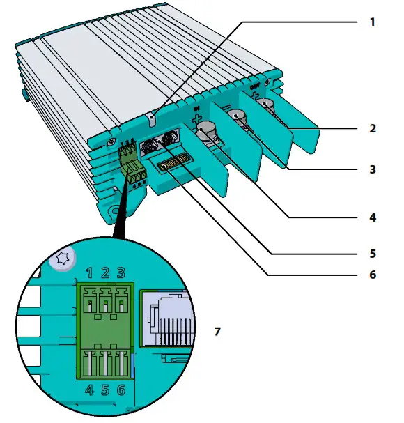
Front panel
| 1 | Status LED |
| 2 | + Output |
| 3 | Ground |
| 4 | + Input |
| 5 | MasterBus (2x) |
| 6 | DIP switch |
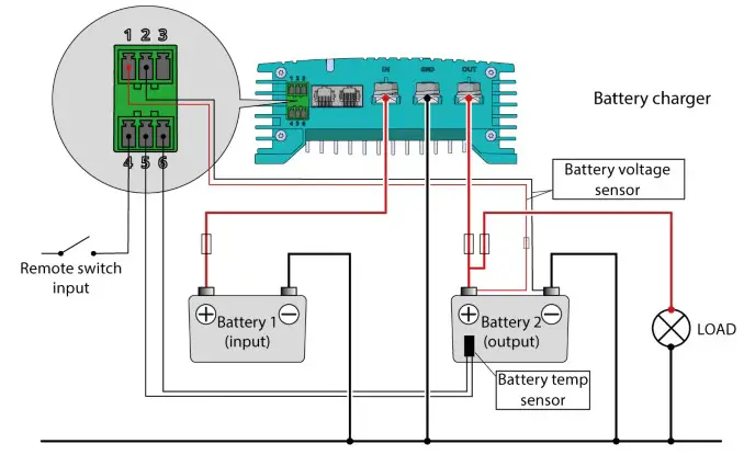
| 7 | Accessories connector Pin 1: + battery voltage sense input Pin 2: – battery voltage sense input Pin 3: not used Pin 4: remote switch input Pin 5-6: battery temperature sensor input |
Installation instructions
Installation steps:
- Place and mount the Mac Plus, see chapter 5
- Connect the Mac Plus, see chapter 6
- Configure the Mac Plus, see chapter 10
![]() CAUTION
CAUTION
Read the entire manual before installing the Mac Plus. Keep the manual at a safe location for future reference.
- Operating temperature range: -20 up to +60 ºC, >40 ºC derating power [-4 up to +140 ºF, >40 ºF derating power].
- Never use the Mac Plus at a location where there is danger of gas or dust explosions.
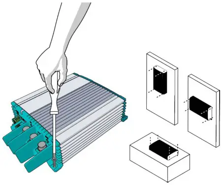
- Mount the Mac Plus in such a way that obstruction of the airflow through the heatsink is prevented. This device requires a minimum of 100 mm (4″) of clearance on every side.
- Do not install the Mac Plus in the same compartment as the batteries. Do not mount the Mac
Plus straight above batteries that might release corrosive sulphur fumes. - Be sure that the output of the supplying source is switched off during installation. Also be sure that no load is connected to the batteries during installation, to prevent hazardous situations.
- Use cables with an appropriate size, see the following table.
Recommended wire sizes DC input/output
| Model | Minimum wire size Input | Minimum wire size Output |
| 12-12-50 | 16 nnm2 [AWG 6] | 16 mm2 [AWG 6] |
| 12-24-30 | 16 mm2 [AWG 6] | 10 mm2 [AWG 8] |
| 24/12-50 | 10 mm2 [AWG 8] | 16 mm2 [AWG 6] |
| 24/24-30 | 10 mm2 [AWG 8] | 10 mm2 [AWG 8] |
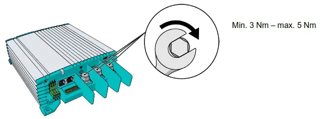
Placement and mounting
Mount the Mac Plus with four M5 screws (3/16″) to a solid flat surface.
Connection
- Mac Plus as a battery charger, see installation drawing A.
- Mac Plus as a stabilized DC power supply, see installation drawing B.
- Use properly sized fuses and wiring. Installation drawing A
Installation drawing A
Installation drawing B
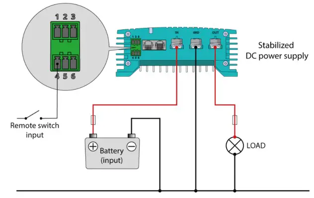
Remote switch input
The remote switch input (pin 4 of the Accessories connector) can be used to enable and disable the battery charger. In a vehicle application, it is recommended to connect the engine run signal. This way, the charger is used when the engine is running and the alternator is charging. The engine run signal can be provided in different ways. For details contact your vehicle distributor. The remote input accepts two different enable levels:
- active low, connect to ground (between 0 and 0.5 V)
- active high, connect to + battery voltage (between 3 and 32 V)
Active low means active when input is low. Active high means active when input is high. The remote switch input configuration can be done by DIP switch (see chapter 7) or by MasterBus (see chapter 9 and 10).
Battery temperature sensor (included)
By installing the Mastervolt temperature sensor, the charge voltages are automatically adapted for deviating temperatures.
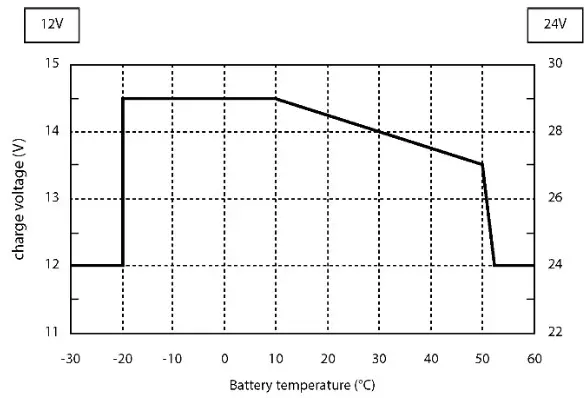 Figure 1. Temperature compensated charging
When the battery temperature is low, the charge voltage increases. In case the battery temperature is high, the charge voltage is decreased. Over charge and gassing are prevented this way. This will extend the life of your battery.
Voltage drop compensation
The Mac Plus can compensate the voltage drop occurring over the output cables. For this purpose, the Mac Plus is equipped with terminals for voltage sense wires. Use 0,75 mm2 [AWG 18], preferably red and black wire, and protect these with a 2 A fuses slow blow. Pay good attention to the polarity of the wires. In order to accurately measure the battery voltage, connect the voltage sense wires as close to the battery poles as possible. The positive and negative voltage sense wires must be connected. Cable losses will be compensated up to a maximum of 2.5 V.
Configuration DIP switches
The Mac Plus settings can be adjusted in two ways:
- By means of DIP switches;
- Via the MasterBus network (with a remote-control panel, or a PC with MasterAdjust software connected via a USB Interface); see chapter 9 and 10. This chapter only describes the DIP switch settings.
Note: DIP switch settings overrule MasterBus settings. If DIP switches are not in their default setting, the corresponding MasterBus setting is grayed out.![]() CAUTION!
CAUTION!
Incorrect settings of the Mac Plus can cause serious damage to your batteries and/or the connected load! Adjustments of settings may be undertaken by authorized personnel only!
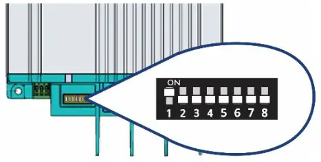
Use a small screwdriver to carefully set the required settings. You may need to remove the MasterBus cables (or Terminator) to be able to access the
| DIP switch 1 | MasterBus communication |
| 0 | Smart on; no MasterBus communication in sleep mode (no load <2mA) |
| 1 | MasterBus communication always on (no load 10mA), provided there is enough input power |
| DIP switch 2 3 4 5 | Charger on conditions | Typical use |
| 0 0 0 0 | MasterBus settings apply, see chapter 9 and 10. Default factory setting: Remote switch input ‘active high’ and input voltage greater than enable voltage setpoint (12.50 V*) | Default factory setting: Recommended setting for vehicle with proper engine run signal |
| 0 0 0 1 | Always on (Remote switch input not used) | When the battery charger must be |
| 0 0 1 0 | Remote switch input ‘active low’ | always active |
| 0 0 1 1 | Remote switch input ‘active high’ | Input voltage greater than enable voltage setpoint (13.50 V*) (Remote switch input not used) |
| 0 1 0 0 | Remote switch input ‘active low’ and input voltage greater than enable voltage setpoint (12.50 V*) | Enable the battery charger by external operating signal |
| 0 1 0 1 | Remote switch input ‘active high’ and input voltage greater than enable voltage setpoint (12.50 V*) | Recommended setting for vehicle with proper engine run signal |
| 0 1 1 0 | Input voltage greater than enable voltage setpoint (13.50 V*) (Remote switch input not used) | Higher enable voltage setpoint. Setting for vehicle without engine run signal |
* For a 24 V battery charger, multiply the voltages by two.
| DIP switch 6 7 8 | Battery type | |
| 0 0 0 | Follow MasterBus setting, see chapter 9 and 10 Default factory setting: Flooded battery | |
| 0 0 1 | Flooded | Bulk: 14.25 | Abs: 14.25 | Float: 13.25 V * |
| 0 1 0 | Gel | Bulk: 14.25 | Abs: 14.25 | Float: 13.80 V * |
| 0 1 1 | AGM | Bulk: 14.25 | Abs: 14.25 | Float: 13.80 V * |
| 1 0 0 | Spiral | Bulk: 14.25 | Abs: 14.25 | Float: 13.80 V * |
| 1 0 1 | Traction | Bulk: 14.55 | Abs: 14.55 | Float: 13.25 V * |
| 1 1 0 | Nicad | Bulk: 14.50 | Abs: 14.50 | Float: 14.50 V * |
| 1 1 1 | Constant voltage | 13,25 V* |
* For a 24 V battery charger, multiply the voltages by two.
Notes:
- For Li-Ion see MasterBus settings, chapter 9 and 10.
- The charge specifications are based on Mastervolt batteries. Specifications for a given chemistry of a different manufacturer may vary. If onnecting batteries of a different manufacturer, make sure the manufacturer’s recommendations are met. Individual adjustments are possible if in the configuration the battery type “User defined” is selected. User defined batteries can only be configured through MasterAdjust, see chapter 9 and 10.
Operation
Battery charger operation modes
| Mode | Explanation |
| Charging | The Mac Plus is in charging mode if it meets the switch-on conditions (see DIP switch/MasterBus settings) |
| Standby | The Mac Plus goes to standby when is does not meet the switch-on conditions (see DIP switch/MasterBus settings) Or Switched off by the on / off button in the MasterBus menu or by a MasterBus event |
| Sleep (low no-load power consumption) | The Mac Plus enters sleep mode when the sleep delay has passed, to reduce the no-load power consumption Every 5 seconds, the Mac Plus scans if the configured battery charger meets the switch-on conditions |
| Alarm | Possible error, connect MasterBus and analyze the situation |
LED indicator
Use the following table to understand the meaning of the LED signals.
| LED color | LED indication | Meaning | What to do? |
| Green | Charging | Normal operation | |
| Blue | Sleep | Normal operation | |
| Blue | Standby | Normal operation | |
| Red-Blue | Software update | Normal operation | |
| Red | Possible error | Connect to MasterBus and analyze the situation |
MasterBus
What is MasterBus![]() All devices that are suitable for MasterBus are marked by the MasterBus symbol MasterBus is a fully decentralized data network for communication between the different Mastervolt system devices. It is a CAN-bus-based communication network which has proven itself as a reliable bus system in automotive applications. MasterBus is used as power management system for all connected devices, such as the inverter, battery charger, generator, and many more. This gives the possibility for communication between the connected devices, for instance, to start the generator when the batteries are low.
All devices that are suitable for MasterBus are marked by the MasterBus symbol MasterBus is a fully decentralized data network for communication between the different Mastervolt system devices. It is a CAN-bus-based communication network which has proven itself as a reliable bus system in automotive applications. MasterBus is used as power management system for all connected devices, such as the inverter, battery charger, generator, and many more. This gives the possibility for communication between the connected devices, for instance, to start the generator when the batteries are low.
MasterBus reduces complexity of electrical systems by using UTP patch cables. All system components are simply chained together. Therefore, each device is equipped with two MasterBus data ports. When two or more devices are connected to each other through these data ports, they form a local data network, called the MasterBus. The results are a reduction of material costs as only a few electrical cables are needed and less installation time.
For central monitoring and control of the connected devices ASG offers a wide range of panels which show full status information of your electrical system at a glance and a push of a button. See www.mastervolt.com for all available options.
New devices can be added to the existing network in a very easy way by just extending the network. This gives the MasterBus network a high degree of flexibility for extended system configuration, not only today, but in the future as well!
ASG also offers several interfaces, making even non-MasterBus devices suitable to operate in the MasterBus network.
How to set up a MasterBus network
Each device that is suitable for the MasterBus network is equipped with two data ports. When two or more devices are connected to each other through these ports, they form a local data network, called the MasterBus. Keep the following rules in mind:
- Connections between the devices are made by standard MasterBus cables (straight UTP). ASG can supply these cables.
- As with all high-speed data networks, MasterBus needs a terminating device on both ends of the network.
- Up to 63 MasterBus devices can be connected together.
- The electric power for the network comes from the connected devices. At least one device in the network should have powering capabilities (see specifications). One powering device can power up to three non-powering devices. As all powering devices are galvanically isolated, multiple powering devices are allowed. Spread the powering devices over the network.
- Do not make ring networks.
- Do not make T-connections in the network.
For more details on networks, please contact your Mastervolt supplier.
MasterBus on the Mac Plus
Monitoring
| Value | Meaning | Default | Adjustable range |
| Status | |||
| Device state | Shows the actual operation mode: Standby I Charging I Alarm I Off | (read only) | |
| Charge state | State of charge algorithm: Off / Bulk / Absorption / Float I Constant voltage | (read only) | |
| Standby | Button to toggle the device state. Note: in the standby mode, the Mac Plus can be switched on again automatically. This happens, for example, after a restart. | On | On, Off |
| General | |||
| Input voltage | Voltage at the input | (read only) | |
| Input current | Current of the input | (read only) | |
| Output voltage | Voltage at the output | (read only) | |
| Output current | Current of the output | (read only) | |
| Bat. volt sense | Battery voltage measured by the battery voltage sensor. If the Shunt device function is enabled for a MasterShunt (MSH) or an MLI Ultra (BAT): voltage measured by the MasterShunt / MLI Ultra. | (read only) | |
| Remote sw. input | Remote input signal detected. Only applicable when Remote input mode is active low or active high configured. | (read only) | |
| Temperatures | |||
| Device | Device temperature | (read only) | |
| Battery | Actual battery temperature measured by the Battery temperature sensor. If no battery temperature sensor is used or when Battery is set to “Li-Ion’: “–” is shown. | (read only) |
Alarm
| Value | Meaning |
| Alarm status | |
| Temperature high | Internal temperature is too high |
| Bat. temp. high | Battery temperature is too high (> 55 ºC [131 ºF]) |
| Bat. temp. low | Battery temperature is too low (< -20 ºC [-4 ºF]) |
| Input high | Input voltage is too high |
| Input low | Input voltage is too low |
| Output high | Output voltage is too high |
| Output low | Output voltage is too low |
| OVP/OCP | Over Voltage Protection or Over Current Protection shutdown |
| HW fault | Internal hardware error |
| Cable loss high | Cable loss is too high (>2.5 V) |
| Shunt mismatch (available in upcoming software update) | Setting for nominal voltage (12 or 24 V) at the MasterShunt or the nominal voltage of the MLi Ultra battery differs from nominal output voltage of the Mac Plus, Check battery voltage and settings of the MasterShunt or voltage of the MLI-Ultra battery. |
Configuration
| Value | Meaning | Factory setting | Adjustable range |
| Device | |||
| Language | Language that is displayed on a monitoring device connected to the MasterBus | English | EN, NL, DE, FR, ES, IT, NO, SV, FI, DA |
| Name | Device name (user defined). The device will be represented by this name throughout the MasterBus network | Plus 12/12 Plus 12/24 Plus 24/12 Plus 24/24 | 0-12 chars |
| Back to default | Button to reset the Mac Plus to default settings | ||
| Remote sw. input | |||
| Mode | Active low: active when the input voltage is 0 – 0.5 V Active high: active when the input voltage is 3 – 32 V Not used: always active | Active high | Not used, Active low, Active high |
| Input threshold | |||
| Enabled | Enabled: input voltage thresholds are active Disabled: input voltage thresholds are not active | Enabled | Enabled, Disabled |
| Enable voltage | Enable input voltage | 12.50 / 25.00 V | 8-16 / 16-32 V |
| Enable delay | Enable delay | 2 s | 0-300 s |
| Disable voltage | Disable input voltage | 12.00 / 24.00 V | 8-16 / 16-32 V |
| Disable delay | Disable delay | 300 s | 0-300 s |
| Instant disable | Disable input voltage, no delay | 11.00 V | 8-16 / 16-32 V |
| Sleep delay | Delay before the Mac Plus switches to sleep mode | 300 s | 0-3600 s |
| Charger | |||
| Battery type | Selection of pre-set charge algorithm. Individual adjustments are only possible if “User defined” is selected here. | Flooded | Flooded, Gel, AGM, Spiral, Li-Ion, Traction, NiCad, Constant voltage, User defined, |
| Max output (limit) | Maximum output (charge) current | 50 A 30 A | 0-50 A 0-30 A |
| Max input (limit) | Maximum input current | 50 A 30 A | 0-50 A 0-30 A |
| Current ramp up | Charge current ramp up after enabling the charger. | 5 Ns | 0-50 A/s |
| Temp. compensate | Temperature compensation for charge voltage | -0.030 V/°C -0.060 V/°C | -0.1 – +0.1 V |
| Shunt | |||
| Shunt device (available in upcoming software update) | Selection of the shunt device to which the Mac Plus is connected. This can either be a MasterShunt (MSH) or an MLI-Ultra battery (BAT). Enabling this function allows to: – Compensate the charge voltage for cable losses; – Adjust the actual Charge state based on the state of charge of the battery; – Compensate the charge voltage for deviating battery temperatures (MasterShunt only). | No connection | No connection, MSH+Product Name, BAT+Product Name |
| Bulk | |||
| Bulk voltage | Bulk voltage | 14.25 / 28.50 V | 8-15 / 16-30 V |
| Max. bulk time | Maximum bulk time | 480 min | 0-1440 min |
| Min. bulk time | Minimum bulk time | 120 s | 0-240 s |
| Start bulk time | Start bulk timer | 13.25 V | 8-15 / 16-30 V |
| Bulk ret. volt | Return to bulk voltage | 12.80 / 25.60 V | 8-15 / 16-30 V |
| Bulk return time | Return to bulk time delay | 30 s | 0-240 s |
| Absorption | |||
| Abs. voltage | Absorption voltage | 14.25 / 28.50 V | 8-15 / 16-30 V |
| Max absorp. time | Maximum absorption time | 240 min | 0-1440 min |
| Min absorp. time | Minimum absorption time | 15 min | 0-240 min |
| Return amps | Return amps (% of maximum charge current) | 6 % or 10 % | 0-50 % |
| Float | |||
| Float voltage | Float voltage | 13.25 / 26,50 V | 8-15 / 16-30 V |
| Constant voltage | |||
| Constant voltage | Constant output voltage | 13.25 / 26.50 V | 8-15 / 16-30 V |
| Input alarm | |||
| High alarm on | High input voltage alarm on | 16.00 / 32.00 V | 8-16 / 16-32 V |
| High alarm off | High input voltage alarm off | 15.50 / 31.00 V | 8-16 / 16-32 V |
| Low alarm off | Low input voltage alarm off | 11.00 / 22.00 V | 8-16 / 16-32 V |
| Low alarm on | Low input voltage alarm on | 10.00 / 20.00 V | 8-16 / 16-32 V |
| Low alarm delay | Low input alarm delay time | 5 s | 0-300 s |
| Output alarm | |||
| High alarm on | High output voltage alarm on | 15.25 / 30.50 V | 8-16 / 16-32 V |
| High alarm off | High output voltage alarm off | 14.75 / 29.50 V | 8-16 / 16-32 V |
| Low alarm off | Low output voltage alarm off | 11.00 / 22.00 V | 8-16 / 16-32 V |
| Low alarm on | Low output voltage alarm on | 10.00 / 20.00 V | 8-16 / 16-32 V |
| Low alarm delay | Low output alarm delay time | 30 s | 0-300 s |
| DIP switch | |||
| 12345678 | DIP switch state 0=off, 1=on | 0 | 0,1 |
Events
A MasterBus device can be programmed to initiate an action at another connected device. This is very helpful in automation of your system but is not required. In MasterBus this is done by means of event-based commands. In the Events tab you can program the Mac Plus to act as an event source. Events which occur during the operation of the Mac Plus will then trigger actions from other products.
| Field | Meaning | Value |
| Event x source | Select an event that triggers an action, for example Battery pre low. | See Event source list |
| Event x target | Select the device that should take action, for example the generator | Selectable targets are system dependent |
| Event x command | Select the parameter that must be changed on the target device, for example Activate. | See command list of the selected device |
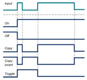
| Event x data | Data translates the input into an output.
• On: status changes to On at first input signal. | Off, On, Copy, Copy Invert, Toggle |
The Mac Plus can be configured as an event source. An event source can be used to initiate an event command and an event action by another device.
| Event source | Meaning |
| Standby | Device state is Standby |
| Bulk | State of charge is Bulk |
| Absorption | State of charge is Absorption |
| Float | State of charge is Float |
| Alarm | Any of the alarms is triggered |
When the Mac Plus is configured as an event target by another device, this device can initiate an event command and an event action to be performed by the Mac Plus.
| Event command | Meaning |
| Standby | Command to switch on/off the Mac Plus. If the Mac Plus was switched off by means of this event command, it will switch on again when it wakes from sleep mode (i.e. after meeting the switch-on conditions, see DIP switch/MasterBus settings). |
| Bulk | Command to start the Bulk state of charge |
| Absorption | Command to start the Absorption state of charge |
| Float | Command to start the Float state of charge |
Trouble shooting
| Malfunction | Possible cause | What to do |
| No output voltage and/or current | No input voltage | Check wiring |
| Input voltage too low | Check input voltage, check configuration | |
| No enable signal on the remote switch input | Check remote switch input | |
| The primary (input) battery is discharged too far | Charge input battery | |
| LED is red | See chapter 11 for an overview of fault indications of the LED’s. | |
| Output voltage too low, charger supplies maximum current | Load connected to the batteries is larger than battery charger can supply. | Reduce load taken from the batteries. |
| Batteries not 100% charged | Measure battery voltage. After some time, this will be higher. | |
| Wrong setting of the charge voltage | Check settings | |
| Charge current too low | Batteries almost fully charged | Nothing, this is normal when the battery is almost fully charged. |
| High ambient temperature | Nothing; if ambient temperature is more than the setting limit, the charge current is automatically reduced. | |
| Batteries not fully charged | Charge current too low | See “Charge current too low” in this table. |
| Current to load is too high | Reduce load taken from the batteries. | |
| Charge time too short | Use a battery charger with higher capacity. | |
| Battery temperature too low | Use the battery temperature sensor. | |
| Defective or old battery | Check battery and replace if necessary. | |
| Wrong setting of the charge voltage | Check settings | |
| Batteries are discharged too fast | Battery capacity reduced due to wastage or sulphation, stagnation | Charge and recharge a few times, this might help. Check battery and replace if necessary. |
| Batteries are too warm, gassing | Defective battery (short circuit in cell) | Check battery and replace if necessary. |
| Battery temperature too high | Use the battery temperature sensor. | |
| Charge voltage too high | Check settings | |
| Slow or no MasterBus communication. | Error in the MasterBus wiring. | Check the MasterBus cables. |
| No terminating device placed at the ends of the network. | MasterBus needs a terminating device on both ends of the network. Check if connected. | |
| MasterBus network is configured as a ring network. | Ring networks are not allowed. Check the connections of the network. | |
Technical specifications
| Mac Plus 12/12-50 | Mac Plus 12/24-30 | Mac Plus 24/12-50 | Mac Plus 24/24-30 | |
| Product code | 81205100 | 81205300 | 81205200 | 81205400 |
| Input specifications | ||||
| Nominal input voltage | 12 V | 12 V | 24 V | 24 V |
| Input voltage range | 10-16 V | 10-16 V | 19-32 V | 19-32 V |
| Max input current | 50 A | 50 A | 30 A | 30 A |
| No load consumption | < 2 mA | |||
| Output specifications | ||||
| Nominal output voltage | 12V | 24V | 12V | 24V |
| Output voltage range | 10-15 V | 20-30 V | 10-15 V | 20-30 V |
| Max output current | 50 A | 30 A | 50 A | 30 A |
| Flat battery charge | yes, reduced (25%) charge current at low (<9 V / <18 V battery voltage | |||
| Protection against overload | yes | |||
| Reverse polarity detection | yes, internally fused, non-replaceable | |||
| Charge characteristic | Mastervolt 3-Step algorithm | |||
| Battery types | Flooded, Li-Ion, Gel, AGM, Spiral, Traction NiCad, Constant voltage, User defined | |||
General specifications
| Galvanic insulation | No |
| Efficiency | > 95% at full output |
| Protection against over-temperature | Yes |
| Weight | 2 kg |
| Dimensions, hxwxd | 255x165x66 mm (10.0×6.5×5.6 inch) |
| Cooling | Natural cooling |
| IP rating | IP23 |
| Connection in- and output | M8 screw terminal, wire size 10 to 50 mm2 [AWG 0 to 8] |
| MasterBus | Yes (not powering) |
| Battery temperature sense | Yes, sensor included |
| Battery voltage sense | Yes, sensor included |
| Remote switch input | Yes (active high / active low) |
| DIP switches | Yes, for basic setup |
| LED | Yes, 3-color LED |
| Operating temperature range | -20 up to +60 ºC, >40 ºC derating power [-4 up to +140 ºF, >104 ºF derating power] |
| Approvals | CE, E-Mark, SAE J1171 & ISO 8846 Ignition Protected |
Battery settings
| Charging specifications | |||||
| Battery type | Flooded (default) | Gel / AGM / Spiral | Li-Ion (MLI) | Traction | NiCad |
| Bulk voltage | 14.25 V* | 14.25 V* | 14.25 V* | 14.55 V* | 14.50 V* |
| Max bulk time | 480 min | 480 min | 480 min | 480 min | 480 min |
| Min bulk time | 120s | 120s | 120s | 120s | 120s |
| Start bulk time | 13.25 V* | 13.25 V* | 13.25 V* | 13.25 V* | 13.25 V* |
| Bulk ret. volt. | 12.80 V* | 12.80 V* | 13.25 V* | 12.80 V* | 13.50 V* |
| Bulk return time | 30 s | 30 s | 240 s | 30 s | 30 s |
| Abs. voltage | 14.25 V* | 14.25 V* | 14.25 V* | 14.55 V* | 14.50 V* |
| Max absorp. time | 240 min | 240 min | 240 min | 240 min | 240 min |
| Min absorb. time | 15 min | 15 min | 15 min | 15 min | 240 min |
| Return amps | 6.0 % IMAX | 6.0 % IMAX | 6.0 % IMAX | 6.0 % IMAX | 6.0 % IMAX |
| Float voltage | 13.25 V* | 13.80 V* | 13.50 V* | 13.25 V* | 14,50 V* |
* For a 24 V battery charger, multiply the voltages by two.
Characteristics
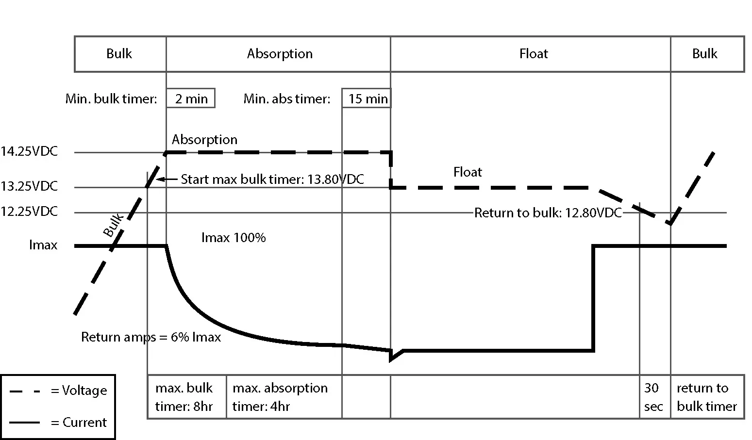
Figure 2. Typical charge characteristic (at 25°C / 77°F). For a 24 V battery charger, multiply the voltages by two.
![]()
![]()
| Europe, Middle East & Africa Technical Support T: +31 (0) 20 34 22 100 E: [email protected] Location & Shipping Advanced Systems Group EMEA Snijdersbergweg 93 1105 AN Amsterdam The Netherlands | Americas & Caribbean Technical Support T: +1 262 293 0600 / 800 307 6702 E: [email protected] Location & Shipping Advanced Systems Group US N85 W12545 Westbrook Crossing Menomonee Falls, WI 53051 United States | Asia Pacific Technical Support T: +64 9 415 7261 E: [email protected] Location & Shipping Advanced Systems Group APAC 42 Apollo Drive Rosedale, Auckland 0632 New Zealand |
Document version: 10000013205/6 (July 22)
Copyright ©2022 Advanced Systems Group EMEA B.V. All rights reserved.


