
MASS 24-50-2 Mass Charger Fully Automatic Battery Charger
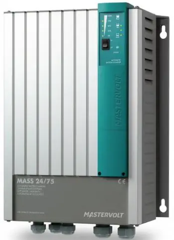
Mass Charger
The Mass Charger is a fully automatic battery charger that is available in various models including:
- MASS 24/50-2
- MASS 24/50 3ph
- MASS 24/75
- MASS 24/75 (120V)
- MASS 24/100
- MASS 24/100 3ph
- MASS 48/25
- MASS 48/50
General Information
The Mass Charger comes with a user and installation manual which contains important safety and operating instructions for the safe and effective use, maintenance, and troubleshooting of the product. It is essential that all users of this product are familiar with the contents of the manual and follow the instructions and safety guidelines carefully.
Safety Instructions
The Mass Charger comes with safety instructions that cover general safety guidelines, warnings regarding the use of batteries, explosive gases, life support applications, and warranty information. It is crucial that all users of this product read and understand these safety instructions before using the Mass Charger.
Installation and Commissioning
The Mass Charger comes with a step-by-step installation guide that must be followed carefully during installation. The installation process includes connection, commissioning,
decommissioning, storage, and transportation instructions. These instructions are essential to ensure safe and effective use of the Mass Charger.
DIP Switch Settings
The Mass Charger has DIP switches that enable users to set various functions of the charger. The DIP switch operation and functions are explained in the manual.
Operation
The Mass Charger has a 3-step+ charge process that ensures safe and effective charging of the battery. It also has an equalize mode and LED indicators that show the status of the charger. The manual provides instructions on how to switch the charger on/off and reset it.
MasterBus
The Mass Charger is equipped with MasterBus technology that enables users to set up a MasterBus network and control the charger remotely. The manual provides instructions on how to set up a MasterBus network and use event-based commands.
Troubleshooting and Technical Data
The manual also provides troubleshooting instructions and technical data such as specifications, dimensions, and characteristics of the Mass Charger.
Important Notice
In case of any discrepancy in the interpretation of different language versions of the manual, the English version shall prevail.
Correct Disposal of the Product
It is essential to dispose of the Mass Charger in an environmentally friendly manner. The manual provides instructions on how to dispose of the product correctly.
Note
The information provided in this response is a summary of the user manual. For detailed information and instructions, please refer to the user and installation manual that comes with the product.
For the latest version of this manual, visit our website: www.mastervolt.com
In case of any discrepancy in the interpretation of different language versions, the English version shall prevail.
GENERAL INFORMATION
Use of this manual
This manual contains important safety and operating instructions for the safe and effective operation, maintenance and possible correction of minor malfunctions of the Mass Charger. It is therefore obligatory that every person who works on or with this product is completely familiar with the contents of this manual, and that he/she carefully follows the instructions and important safety instructions contained herein.
Validity of this manual
All the specifications, provisions and instructions contained in this manual apply solely to standard versions of the Mass Charger.
This manual is valid for the following models:
These models are further mentioned as “Mass Charger”.
Mastervolt offers a wide range of products for your electrical installation. For an extensive overview of all our products, please visit our website www.mastervolt.com.
Liability
Mastervolt can accept no liability for:
- Consequential damage due to use of the Mass Charger.
- Use that is inconsistent with the purpose of the product.
- Possible errors in the manuals and their results.
Disclaimer: Our products are subject to continual development and improvement. Therefore, additions or modifications to the products may cause changes to the technical data and functional specifications. No rights can be derived from this document. Please consult our most current Terms & Conditions of Sale.
Identification label
The following picture is only an example!
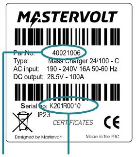
Part number Serial number K201R0010 with device version “R”
Figure 1. Identification label
The identification label is located at the right-hand side of the Mass Charger. Important technical information required for service and maintenance can be derived from the identification label.
CAUTION!
Never remove the identification label. This will void the warranty.
Correct disposal of this product
This product is designed and manufactured with high quality materials and components, which can be recycled and reused. Please be informed about the local separate collection system for electrical and electronic products. Please act according to your local rules and do not dispose of your old products with your normal household waste.
SAFETY INSTRUCTIONS
Read the entire manual before using the Mass Charger. Keep this manual in a secure place.
WARNING!
This chapter describes important safety and operating instructions for use of a Mass Charger in residential, recreational vehicle (RV) and marine applications.
General
- To reduce the risk of electric shock – Do not expose Mass Charger to rain, snow, spray, moisture, excessive pollution and condensing circumstances. To reduce risk of fire hazard, do not cover or obstruct the ventilation openings. Do not install the Mass Charger in a non-ventilated room, overheating may result.
- Use of an attachment or spare part not recommended or sold by Mastervolt may result in a risk of fire, electric shock, or injury to persons.
- The Mass Charger is designed to be permanently connected to an AC and DC electrical system. Installation of, and work on the Mass Charger, may be carried out only by a qualified, authorised and trained technician or electrician, consistent with the locally applicable standards and regulations.
- Make sure that all wiring is properly installed and in good electrical condition; and that wire size is large enough for AC current rating of the Mass Charger. Check the wiring on a regular base, at least once a year. Do not use the Mass Charger when the wiring is undersized or damaged.
- Do not operate the Mass Charger if it has received a sharp blow, been dropped, or otherwise damaged in any way; take it to qualified personnel.
- Except for the connection compartment (see section Overview connection compartment3.11 on page 9), the Mass Charger may not be opened or disassembled. There are no serviceable parts inside the cabinet. Take it to qualified, authorized and trained service personnel when service or repair is required. Incorrect reassembly may result in a risk of electric shock or fire. Only qualified, electrician installers are authorized to open the connection compartment.
- To reduce risk of electric shock, disconnect the Mass Charger from both AC and DC electrical system before attempting any maintenance or cleaning. Turning off controls will not reduce this risk.
- The Mass Charger must be provided with an equipment-grounding conductor to the AC input ground terminal. Grounding and all other wiring must comply with local codes and ordinances.
- Short circuiting or reversing polarity will lead to serious damage to batteries, Mass Charger, wiring as well as accessories. Fuses cannot prevent damage caused by reversed polarity and the warranty will be void.
- case of fire, you must use the fire extinguisher which is appropriate for electrical equipment.
- If applied in a marine application in the United States, external connections to the Mass Charger shall comply with the United States Coast Guard Electrical Regulations (33CFR183, Sub part I).
Explosive gases
- WARNING: risk of explosive gases. Working in vicinity of a lead-acid battery is dangerous. Batteries generate explosive gases during normal battery operation. For this reason, it is of utmost importance that each time before using the Mass Charger, you read this manual and follow the instructions exactly. To reduce risk of battery explosion, follow these instructions and those published by battery manufacturer and manufacturer of any equipment you intend to use in vicinity of the battery. Review cautionary marking on these products.
- DANGER: To reduce the risk of explosion – Never use the Mass Charger in situations where there is danger of gas or dust explosion or an area in which ignition-protected equipment is required.
Warnings regarding the use of batteries
- Someone should be within range of your voice or close enough to come to your aid when you work near a lead-acid battery.
- Have plenty of fresh water and soap nearby in case battery acid contacts skin, clothing, or eyes.
- Wear complete eye protection and clothing protection. Avoid touching eyes while working near battery.
- If battery acid contacts skin or clothing, wash immediately with soap and water. If acid enters eye, immediately flood eye with running cold water for at least 10 minutes and get medical attention immediately.
- NEVER smoke or allow a spark or flame in vicinity of a battery or engine.
- Do not short circuit batteries, as this may result in explosion and fire hazard! Be extra cautious to reduce risk of dropping a metal tool onto a battery. It might spark or short-circuit battery or other electrical part and may cause explosion.
- Remove personal metal items such as rings, bracelets, necklaces, and watches when working with a battery. A battery can produce a short-circuit current high enough to weld a ring or the like to metal, causing a severe burn.
- Only use the Mass Charger for charging Lead-acid, NiCad and Li-ion batteries and the supply of users attached to these batteries, in permanent systems. Do not use the Mass Charger for charging dry-cell batteries that are commonly used with home appliances. These batteries may burst and cause injury to persons and damage to property.
- NEVER charge a frozen battery.
- Excessive battery discharge and/or high charging voltages can cause serious damage to batteries. Do not exceed the recommended limits of discharge level of your batteries.
- If it is necessary to remove a battery, always remove the grounded terminal from the battery first. Make sure all accessories are off, so as not to cause an arc.
- Be sure that the area around the battery is well ventilated while the battery is being charged. Refer to the recommendations of the battery manufacturer.
- Batteries are heavy! It may become a projectile if it is involved in an accident! Ensure adequate and secure mounting and always use suitable handling equipment for transportation.
- Study all battery manufacturer’s specific precautions while charging and recommended rates of charge. Note that the Mass Charger charge specifications are based on Mastervolt batteries. Specifications for a given chemistry of a different manufacturer may vary.
If connecting batteries of a different manufacturer, make sure the manufacturer’s recommendations are met.
Warning regarding life support applications
Mastervolt products are not designed to be used as component of medical equipment, unless negotiated in the form of a written agreement between customer and/or manufacturer and Mastervolt. Such agreement will require the equipment manufacturer either to contract additional reliability testing of the Mastervolt parts and/or to commit to undertake such testing as a part of the manufacturing process. In addition the manufacturer must agree to indemnify and not hold Mastervolt responsible for any claims arising from the use of the Mastervolt parts in the life support equipment.
Warranty
The Mastervolt product warranty covers the Mass Charger for the first two years after the purchase date, on the condition that the product is installed and used according to the instructions in this manual.
Installation or use that do not comply with these instructions may result in under performance, damage or failure of the product and may void this warranty. The warranty is limited to the cost of repair and/or replacement of the product. Costs of labor or shipping are not covered by this warranty.
INSTALLATION
During installation and commissioning of the Mass Charger, the important safety instructions are applicable at all times. See chapter 2 on page 4.
Please check the contents of the box before you start with the installation. The contents of the box need to be:
- the Mass battery charger;
- battery temperature sensor (incl. 6m cable);
- a MasterBus terminator;
- the user manual.
If one of these items is missing, please contact your Mastervolt dealer.
Location
Choosing a location to install:
- Install the Mass Charger in a well-ventilated room protected against rain, snow, spray, vapour, bilge, moisture and dust.
- Ambient temperature: 0…60°C/32°F…140°F; (power derating above 40°C/104°F to decrease the internal heat sink temperature).
- Humidity: 0-95% non-condensing.
- Never use the Mass Charger at a location where there is danger of gas or dust explosions
- Mount the Mass Charger in such a way that obstruction of the airflow through the ventilation openings is prevented. No objects must be located within 10cm/4inch around the Mass Charger.
- Mount the Mass Charger vertically, with the connecting cables downwards.
- Do not install the Mass Charger in the same compartment as the batteries. Do not mount the Mass Charger straight above the batteries because of possible corrosive sulphur fumes.
Connections
Before making the connection between the battery charger and the system, be sure that the AC and DC system are switched off. Remove the fuses to protect yourself against unexpected start-up.
Wiring
CAUTION!
The wire and fuse sizes stated in this manual are given as example only. Prescribed wire and fuse sizes may be different due to local applicable regulations and standards.
AC wiring
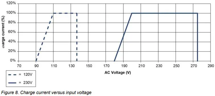
Check if the voltage of your mains source or generator corresponds with the AC input voltage of the battery charger as mentioned on the type number plate. See section 1.4 on page 3.
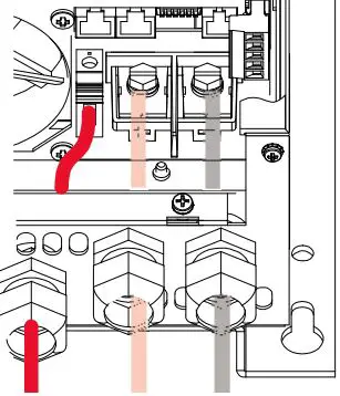
It is important that the green/ yellow earth wire is ± 1 cm (0.4 inch) longer than the other wires. By accidentally pulling at the cable, the earth wire stays connected to the Mass Charger longer which offers additional safety.
For a safe installation the correct wire cross section must be applied. Do not use a cross section that is smaller than indicated. See the following table to select the appropriate cross section for the AC wiring (up to 6m/20ft length):
| AC Current Minimum cross section: | ||
| 6-12A | 1.5mm² | 14AWG |
| 12-20A | 2.5mm² | 12AWG |
| 20-32A | 4.0mm² | 10AWG |
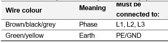
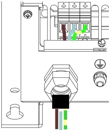
Connection of AC wiring and recommended colours
• 230V [120V] installations
| Wire colour | Meaning | Must be connected to: |
| Brown or black [black] | Phase | L1 |
| Blue [white] | Neutral | N |
| Green/yellow [green] | Earth | PE/GND |
400V installations (Mass 24/50 3ph & 24/100 3ph):
AC safety grounding
WARNING!
The ground wire offers protection only if the cabinet of the Mass Charger is connected to the safety ground. Connect the ground terminal (PE/GND) to the hull or the chassis.
CAUTION!
For safe installation it is necessary to insert an RCD (Residual Current Device; earth leakage switch) in the AC input circuit of the Mass Charger.
DC wiring
Keep the cable connection between charger and batteries as short as possible. If available, use coloured battery cables. If this is not possible, mark the plus and the minus cables with coloured insulating tape (e.g. red for plus and blue/black for minus). Use the following diameters:
| Mass Charger | Length <3 m | Length 3-6 m |
| Mass 24/50-2 MB | 25mm² | 35mm² |
| Mass 24/50 3ph MB | 25mm² | 35mm² |
| Mass 24/75 MB | 25mm² | 35mm² |
| Mass 24/75 (120V) MB | 25mm² | 35mm² |
| Mass 24/100 MB | 35mm² | 50mm² |
| Mass 24/100 3ph MB | 35mm² | 50mm² |
| Mass 48/25 MB | 10mm² | 16mm² |
| Mass 48/50 MB | 25mm² | 35mm² |
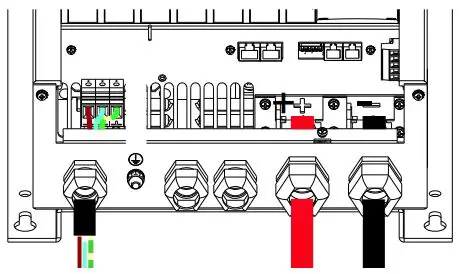
Connection of main batteries
- Pull the cables through the cable glands of the Mass Charger.
- Crimp on ring terminals to the cable:
- ring M6 for 24/50-2, 48/25;
- ring M8 for 24/75, 24/75 (120V), 24/100, 48/50, 24/50 3ph and 24/100 3ph.
- Connect the cables to the terminals of the Mass Charger. Pay attention to the polarity, positive on positive/negative on negative.
- Integrate a suitable fuse (charger fuse) in the positive cable. When using a DC distribution with fuses, no additional fuse is necessary.
- Cut the cables to length and crimp on the ring terminals. Connect the cable to the DC distribution or batteries.
CAUTION!
Reversing the positive and negative battery poles will severely damage the Mass Charger.
Lay the positive and negative cables next to each other to limit the electromagnetic field around the cables. The negative cable should be connected directly to the negative post of the battery bank or the ground side of a current shunt. Do not use the hull or chassis frame as the negative conductor.
Battery capacity
Always follow the instructions published by the battery manufacturer.
| Mass Charger Recommended battery capacity | ||
| Mass 24/50-2 | 100Ah | – 500Ah |
| Mass 24/50 3ph | 100Ah | – 500Ah |
| Mass 24/75 | 150Ah | – 750Ah |
| Mass 24/75 (120V) | 150Ah | – 750Ah |
| Mass 24/100 | 200Ah | – 1000Ah |
| Mass 24/100 3ph | 200Ah | – 1000Ah |
| Mass 48/25 | 50Ah | – 250Ah |
| Mass 48/50 | 100Ah | – 500Ah |
Battery isolator
If one or more batteries or battery sets must be charged at the same time via one output, a battery isolator should be used. This isolates the different battery sets to prevent one discharging the other. Mastervolt offers several Battery Isolators. Please refer to www.mastervolt.com .
A battery isolator causes a voltage drop of 0.6V. This can be compensated in two ways:
- By changing DIP switch 4 to On (Diode enabled);
- By using the voltage sense function (see section 3.8 on page 8);
CAUTION!
Never use both methods. Your batteries will be overcharged and severely damaged!
If you use a ‘voltage drop free’ battery isolator, like the Mastervolt Battery Mate, no compensation is needed.
For a proper installation, see the connection diagram that comes with the battery isolator.
Connection of second battery (3A output)
The Mass 24/50-2 MB is standard equipped with a second charge output which can be used to give a maintenance charge to a small second battery set like a starter battery. The maximum charge current of the second output is 3A, which comes from the main output.
- Use 2.5 to 4mm2 cable for the connection.
- Connect the minus of the second battery to the minus of the main battery.
- Connect the plus of the second battery to the +3A terminal of the Mass Charger (Figure 3 and Figure 4).
- Integrate a 10A slow blow fuse in the plus cable.
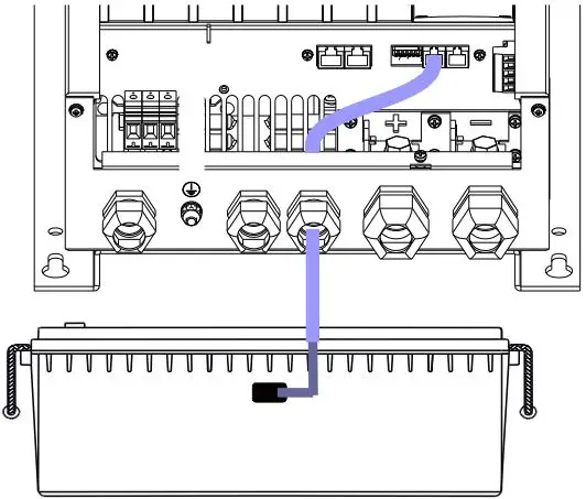
Temperature sensor
The standard temperature sensor is provided with 6m cable and a double-sided tape for easy installation.
- Make sure that the side of the battery that you want to place the sensor, is clean and grease-free.
- Remove the piece of paper from the tape and stick the sensor on the battery.
- Plug the modular cable into the terminal at the right of the Mass Charger (see Figure 3 on page 9). For the C3 enclosure (refer to specifications) both “RS232” and “analog” are suitable.
It is not necessary to shorten the cable. When you want to shorten it anyway, please notice the polarity of the plug and use the old connector as an example.
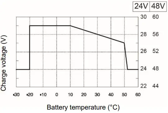
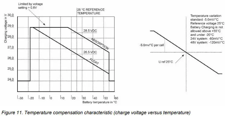
Now when the battery temperature is low, the charge voltage increases and when the battery temperature is high, the charge voltage is decreased. This prevents overcharge, and gassing, which increases the battery’s life time substantially.
Voltage sense
If required, DC cable losses can be compensated by using the sense function. This will shorten the charge time.
- Use 0,75mm2, preferably red and black wire and secure these with fuses of 2A slow blow.
- Connect the wires with the two upper terminals of the green connector at the right side of the cabinet (see Figure 3 on page 9). Pay extra attention to the polarity of the wires, red on +S and black on -S.
- Now connect the other side of the wires: black on the minus of the battery and red on the plus of the battery.
Alarm function
To control external equipment, the charger is equipped with a potential free contacts alarm relay; see Figure 3 on page 9. The alarm function has two modes: standard (factory setting) and DC alarm mode (continuous mode). The maximum switch current of the relay is 1A. Exceeding the setpoints will activate the alarm (see page 16).
Standard alarm mode
In this mode the relay responds to all fault conditions that the Mass Charger can detect such as: no AC input voltage, low DC voltage, voltage sense failure, temperature sense failure.
DC alarm mode
To enable this mode a DIP switch setting needs to be changed (switch 1 and 2 at ON). The alarm now works as a DC alarm and responds to the battery voltage only.
Note: In the DC alarm mode the electronics stay active permanently and drain a very small current of ±25mA, also when the Mass Charger is switched off.
RJ12 splitter for enclosure C2
The RJ12 connector (QRS232 communication port) can be used to connect the battery temperature sensor or the remote panel (not included). Use a RJ12-splitter to connect both at the same time (not included).
Overview connection compartment
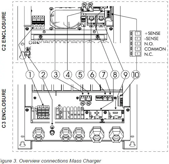
- Screw terminals AC input: L1, N, PE (models 24/50 3ph and 24/100 3ph: L1, L2, L3, PE)
- Earth stud
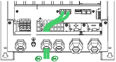
- MasterBus connector
- MasterBus connector
- Output (battery) positive connector (maximum 3A)
- RS232/Temperature sensor connector
- Analog/Temperature sensor connector
- Output (battery) positive connector
- Output (battery) negative connector
- Voltage sense/ potential free alarm contact
Materials
Make sure you have all the parts you need to install the Mass Charger:
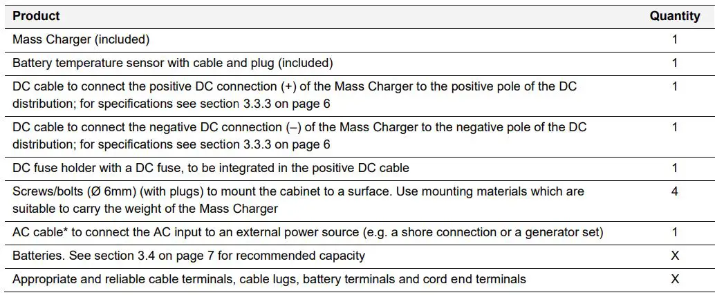
* Double insulated three-wire cable with wire colours according to the locally applicable regulations. The applicable length and wire diameter depend on the electrical installation (see section 3.3.1 on page 6).
We recommend as a minimum tool kit:
- Socket wrench 13mm to fix the DC input (battery) cables
- Flat blade screwdriver 1.0 x 4.0mm to fix the screw terminals
- Tools to fix the screws/bolts (Ø 6mm) with plugs to mount the cabinets to a surface
- Philips screwdriver to open the connection area of the Mass Charger
- 2mm flat blade screwdriver for the sense terminal (see Figure 3, point 10).
Connection
WARNING!
Let installation work be done by a licensed electrician. Before beginning with the connection of the wiring, make the AC distribution as well as the DC distribution voltage free.
Note: If the battery temperature remains within 15-25°C, the battery temperature sensor is optional.
CAUTION!
Too-thin cables and/or loose connections can cause dangerous overheating of the cables and/or terminals. Therefore, tighten all connections well, in order to limit transition resistance as far as possible. Use cables of the correct size.
Note: The Mass Charger supports MasterBus and RS 232 compatible remote control panels.
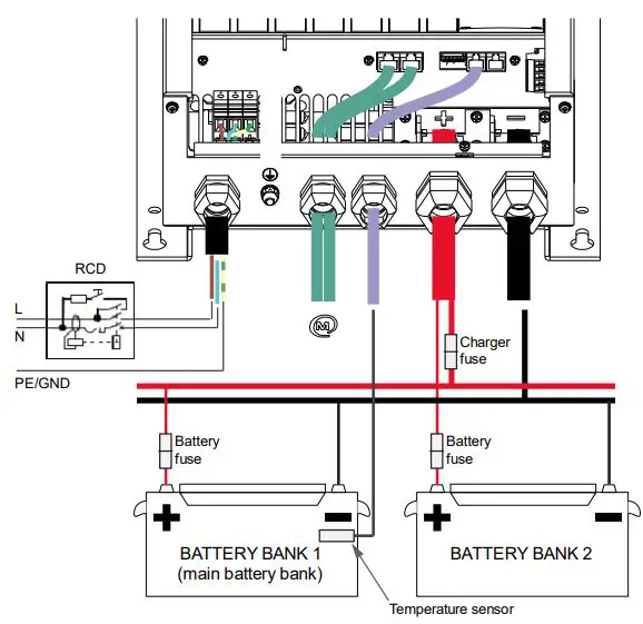
The following schematic illustrates the general placement of the Mass Charger. It is not meant to provide detailed wiring instructions for any particular electrical installation.
Installation step-by-step
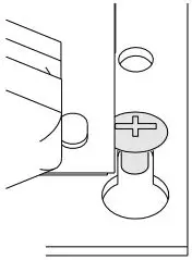
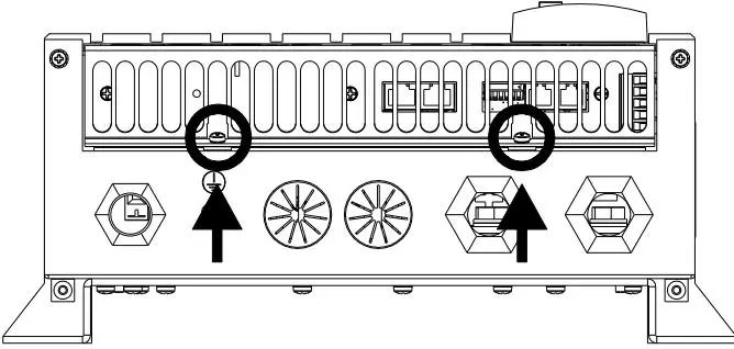
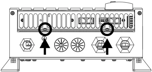
- Mark the position of the mounting spots using the drilling dimensions.
- Place the four screws first and hang the Mass Charger over them. Then fix the Mass to the wall by securing the screws.

- Open the connection compartment by loosening the two screws.

- Feed the AC wiring through the cable gland and connect the wiring to the screw terminals. Tighten the cable gland firmly.

- Connect the DC cabling of the house bank, positive to +, negative to – .

- Option for model 24/50:
Connect the DC wiring of the second battery bank (max. 3A). This bank has a common negative with the main battery.
- Attach the battery temperature sensor to the casing of the main battery bank.
Plug the temperature sensor cable into the “Temp.Sensor” jack. See also Figure page 9.
- Option: Connect the Mass Charger to the MasterBus network.

- The factory setting of the Mass Charger is optimal for most installations. Sometimes however, it is desirable to change these settings. See chapter 4 (page 13) and section 6.3 (page 15).
- Check all wiring. If everything is all right, close the connection compartment by fixing the two screws.

- Continue with section 3.15 for commissioning of the Mass Charger.
Commissioning after installation
Note: When your Mass Charger is not new, you have to consider that former users may have changed the settings. Reset the Mass Charger to factory settings when there is any doubt (see section 6.3 on page 15).
General
The factory settings of the Mass Charger are optimal for most installations. With some applications however, it is desirable to change these settings. Therefore, several adjustments can be made. See chapters 4 and 6.3.
Note: The DIP switches must be adjusted prior to commissioning. All other settings can only be configured after commissioning.
CAUTION!
Check the polarity of all wiring before commissioning: positive connected to positive (red cables), negative connected to negative (black cables).
If all wiring is OK, place the DC fuse(s) of the DC distribution to connect the batteries to the Mass Charger.
WARNING!
When placing this fuse, a spark can occur, caused by the capacitors used in the Mass Charger.
Now the Mass Charger is ready for operation. After switching on the AC power supply the Mass Charger will initiate the charging process.
MasterBus
Adjustment of the settings of the Mass Charger can be made by means of DIP switches or via the MasterBus network (by means of an USB interface connected to a PC with MasterAdjust software). Some settings can only be changed via the MasterBus interface. See section 6.3 on page 15 for an overview of all available MasterBus settings.
Decommissioning
If it is necessary to put the Mass Charger out of operation, follow the instructions in order of succession as described below:
- Switch the Mass Charger to OFF.
- Remove the DC fuse(s) of the DC distribution and/or disconnect the batteries.
- Remove the AC fuse(s) of the AC input and/or disconnect the AC mains.
- Open the connection compartment of the Mass Charger.
- Check with a suitable voltage meter whether the inputs and the outputs of the Mass Charger are voltage free.
- Disconnect all wiring.
Now the Mass Charger can be demounted in a safe way.
Storage and transportation
When not installed, store the Mass Charger in the original packing, in a dry and dust free environment.
Always use the original packing for transportation. Contact your local Mastervolt dealer for further details if you want to return the apparatus for repair.
DIP SWITCH SETTINGS
The Mass Charger settings can be adjusted in two ways:
• By means of DIP switches;
• Via the MasterBus network (by means of a remote control panel or an interface connected to a PC with MasterAdjust software); see section 6.3 on page 15.
Note: Once a DIP switch has been set to On, MasterBus presets are disabled but people can still change the settings!
CAUTION!
Invalid settings of the Mass Charger can cause serious damage to your batteries and/or the connected load! Adjustments of settings may be undertaken by qualified personnel only!
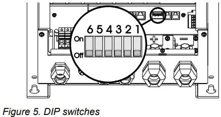
DIP switch operation
The Mass Charger has six DIP switches. These switches are operated by flipping the levers to the other position, using a small screwdriver.
| DIP SWITCH | 5 | 4 | 3 | 2 | 1 |
| Standard | 0 | 0 | 0 | 0 | 0 |
| Diode | 0 | 1 | 0 | 0 | 0 |
| Gel/AGM | 0 | 0 | 1 | 0 | 0 |
| Diode + Gel/AGM | 0 | 1 | 1 | 0 | 0 |
| Traction | 0 | 0 | 0 | 1 | 0 |
| Traction + Diode | 0 | 1 | 0 | 1 | 0 |
| ContMon + Traction | 0 | 0 | 1 | 1 | 0 |
| ContMon + Traction + Diode | 0 | 1 | 1 | 1 | 0 |
| ForceFloat | 0 | 0 | 0 | 0 | 1 |
| ForceFloat + Diode | 0 | 1 | 0 | 0 | 1 |
| ForceFloat + Gel/AGM | 0 | 0 | 1 | 0 | 1 |
| ForceFloat + Diode + Gel/AGM | 0 | 1 | 1 | 0 | 1 |
| ContMon | 0 | 0 | 0 | 1 | 1 |
| ContMon + Diode | 0 | 1 | 0 | 1 | 1 |
| ContMon + Gel | 0 | 0 | 1 | 1 | 1 |
| ContMon + Diode + Gel/AGM | 0 | 1 | 1 | 1 | 1 |
| Lithium-ion (Mastervolt MLI) | 1 | 0 | 0 | 0 | 0 |
| Lithium-ion + Diode | 1 | 1 | 0 | 0 | 0 |
| Lithium-ion + ForceFloat | 1 | 0 | 0 | 0 | 1 |
| Lithium-ion + ContMon | 1 | 0 | 0 | 1 | 1 |
- ContMon: Continuous monitor mode. MasterBus, RS232 and DC alarm stay functioning at mains failure. Remote stays functioning if it has its own power source.
- Diode: Diode compensation on (+0.6V)
- Gel/AGM: Gel/AGM compensation on (during float +1.1V or 2.2V)
- Traction Traction charging (+0.7 or 1.4V during bulk and +0.4 or 0.8V in absorption).
- Force float: One step charge program with fixed float voltage.
OPERATION
Introduction
The Mass charger is a fully automatic, high efficiency battery charger/rectifier. The Mass Charger not only charges batteries rapidly and safely, it supplies the connected consumers at the same time. In addition, the Mass Charger is secured against short circuit, overload and high temperatures in an industrial environment.
Switching on/off
Activate the Mass Charger by switching the main switch to the ON position. When no error is present, the charger LED illuminates green and the Mass Charger starts charging.
Move the switch to the OFF position to switch off the Mass Charger!
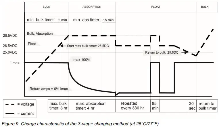
The 3-step+ charge process
The Mass charger is equipped with an intelligent 3-step+ charge characteristic which takes care of an optimal charge of your batteries. See Figure 6 and Figure 9 (page 22) for more details.

Reset the Mass Charger
Set the main switch to off.
Switch on again.
The Mass Charger automatically resumes operation in Bulk stage after it was disconnected from an AC source.
Equalize mode
An equalizing charge can be necessary after very deep discharges and/or inadequate charges. This has to be carried out according to the specifications of the battery manufacturer.
WARNING!
Equalization is ONLY applicable for flooded batteries and will damage Gel/AGM/Spiral type batteries!
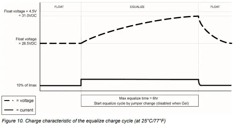
Incorrect use of the equalize mode may lead to hazardous situations. During equalizing the batteries are brought into the gas state and permitted load voltages may be exceeded (refer to Figure 10 on page 23 for characteristics). For these reasons the equalizing mode should only be used by trained technical engineers.
The equalizing mode can only be started when the Mass Charger is in float operation. To start the equalize mode, select Equalize in the MasterBus device settings (see section 6.3 on page 15).
LED indicators
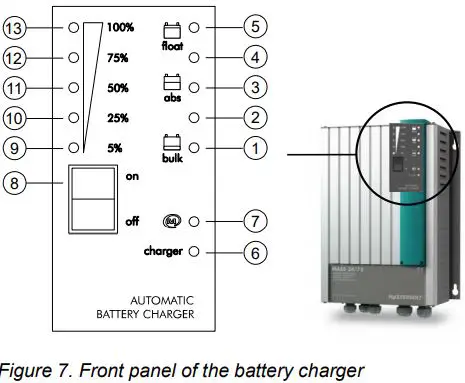
During normal operation the charger LED (6) is green.
When all charge process status LEDs (1 to 5) are on, the battery is fully charged. For details refer to Figure 9 on page 22.
1…5 Status LEDs charge process
Charger status LED
˗ Green = on
˗ Off = off
˗ Red = fault condition:
6 +1: Battery sense error
6 +2: Charger temperature too high
6 +3: Short circuit indication, charger will reduce the charge current to 25%
6 +4: DC error, DC voltage too low or too high
6 +5: Temperature sense error
Status LED MasterBus communication
˗ Green = MasterBus communication ˗
Off = no MasterBus communication
8 Main or on/off switch
9…13 Status LEDs charge current
MASTERBUS
About MasterBus
All devices that are suitable for MasterBus are marked with the MasterBus symbol.
MasterBus is a CAN based, fully decentralized data network for communication between Mastervolt devices. MasterBus is used as power management system for all connected equipment, such as the inverter, battery charger, generator and many more. Every device that is compatible with MasterBus is equipped with two data ports. The devices are simply chained together, forming a local data network. Monitoring panels such as the EasyView 5 can be used for monitoring and control of all connected MasterBus equipment.
CAUTION!
Never connect a non-MasterBus device to the MasterBus network directly! This will damage all connected MasterBus devices.
How to set up a MasterBus network
- Connections between the devices are made by standard straight MasterBus cables. Mastervolt can supply these cables.
- Up to 63 MasterBus devices can be connected together.
- MasterBus needs a terminator on both ends of the network.
- The electric power for the network comes from the connected devices according to the rule: 1 powering/3 non powering.
- Do not make ring networks.
- Do not make T-connections in the network.
MasterBus Settings
| Meaning | Factory setting | Adjustable range | |
| Device | |||
| Language | Language that is displayed on a monitoring | English | EN, NL, DE, FR, ES, IT, |
| device connected to the MasterBus. | NO, SV, FI, DA | ||
| Name | Name for the Mass Charger. | CHG Mass+type* | 0-12 characters |
| Device | Device name recognized by MasterBus. | Mass Charger | – |
| Battery name | Name for the main battery bank. | House Bank | 0-16 characters |
| Factory settings | Option to reset the Mass Charger to default | ||
| settings. | |||
| Presets | |||
| Diode | Option for charger diode +0.6V voltage | Disabled | Disabled, |
| compensate | compensation. If it is enabled, the compensation value is adjustable. | Enabled: 0-2.50V | |
| Forced float | Option for Forced Float or constant voltage | Disabled | Disabled, Enabled |
| charging. If it is enabled, Forced Float voltage is | |||
| adjustable. | |||
| Continuous mode | Option to keep MasterBus powered by the battery | Disabled | Disabled, Enabled |
| when the Mass Charger is disabled. | |||
| Battery | The battery type settings are based on Mastervolt | Flooded | User defined, Gel/AGM, |
| batteries. If connecting batteries of a different | Flooded, Traction, NiCad, | ||
| manufacturer, make sure the manufacturer’s | Lithium-ion | ||
| recommendations are met. Should this not be the | |||
| case, then “User defined” must be selected to | |||
| change the settings. | |||
| Equalize | Option to enable Equalizing. Shows only when no | ||
| other battery type has been selected. |
| Meaning | Factory setting | Adjustable range | |
| General | |||
| Max. current | Maximum charge current, adjustable model dependent. | (Max current)* | 0 – Imax* |
| Temp. compensate | Charge voltage compensation for temperature (V/°C). | -0.060/-0.120V/°C | -1.000 – 1.000V/°C |
| Output reduction | Output reduction that can be used as target event to adjust the maximum current. | 0% | 0-90% |
| Relay | Alarm set points | ||
| DC Alrm high on | Alarm DC High on | 32.00/64.00V | 16.00-32.00 / 32.00-64.00V |
| DC Alrm high off | Alarm DC High off | 30.00/60.00V | 16.00-32.00 / 32.00-64.00V |
| DC Alrm low on | Alarm DC low on | 20.00/40.00V | 16.00-32.00 / 32.00-64.00V |
| DC Alrm low off | Alarm DC low off | 22.00/44.00V | 16.00-32.00 / 32.00-64.00V |
| DC Alrm delay | Alarm delay time | 30 sec | 0-255 sec |
| Bulk | |||
| Bulk voltage | Bulk voltage | 28.50/57.00V | 16.00-32.00 / 32.00-64.00V |
| Max. bulk time | Maximum bulk timer | 480 min | 0-600 min |
| Min bulk time | Minimum bulk timer | 2 min | 0-600 min |
| Start bulk time | Voltage at which to start the bulk timer. | 27.60/55.20V | 16.00-32.00 / 32.00-64.00V |
| Bulk ret. volt. | Return to Bulk voltage | 25.60/51.20V | 16.00-32.00 / 32.00-64.00V |
| Bulk return time | Adjustable Return to Bulk time after the Return to Bulk voltage has been reached. | 30 sec | 0-255 sec |
| Absorption | |||
| Abs. voltage | Absorption voltage | 28.50/ 57.00V | 16.00-32.00 / 32.00-64.00V |
| Max absorption | Maximum absorption timer | 240 min | 0-600 min |
| Min absorp. time | Minimum absorption timer | 15 min | 0-180 min |
| Return amps | Return to Float current (in A) | 6.0 %*I max | 0-25% * I max |
| Float | |||
| Float voltage | Float voltage | 26.50/53.00V | 16.00-32.00 / 32.00-64.00V |
| Equalize voltage | Equalize voltage | 31.00/62.00V | 16.00-32.00 / 32.00-64.00V |
| Equalize time | Equalize time | 360 min | 0-600 min |
Note: the following charge specifications are based on Mastervolt batteries. Specifications for a given chemistry of a different manufacturer may vary
| Charging specifications | Battery type | ||
| Traction | NiCad | Lithium-ion (Mastervolt MLI) | |
| Bulk voltage | 29.20/58.40V | 29.00/58.00V | 28.50/57V |
| Max bulk time | 480 min | 480 min | 480 min |
| Min bulk time | 2 min | 2 min | 2 min |
| Start bulk time at | 27.60/55.20V | 26.50/53.00V | 26.50/53.00V |
| Return to bulk voltage | 25.60/51.20V | 20.00/40.00V | 26.30/52.60V |
| Bulk return time | 30 sec | 30 sec | 240 sec |
| Absorption voltage | 28.90/57.80V | 29.00/58.00V | 28.50/57V |
| Max abs. time | 480 min | 480 min | 240 min |
| Min abs. time | 15 min | 15 min | 15 min |
| Return amps | 6.0 %*I max | 6.0 %*I max | 6.0 %*I max |
| Float voltage | 26.50/53.00V | 29.00/58.00V | 27/54V |
Depending on model
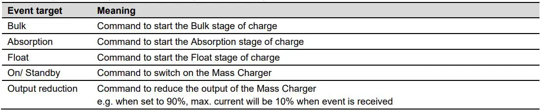
Event based commands
With MasterBus a device can be programmed to initiate an action at another connected device. This is done by means of event-based commands
Events
| Field | Meaning | Factory setting | Adjustable range |
| Event x source | Event-based command. | Disabled | See Event source list. |
| Mass Charger event that should result in an action by | |||
| another device on the MasterBus network. | |||
| Event x target | Select a connected MasterBus device that should take | Select… | Selectable targets are |
| action due to a Mass Charger event. | system dependent. | ||
| Event x | Action to be taken by the target device. | Select… | See command list in |
| command | selected device manual | ||
| Event x data | Data is linked to the command. | Off | Off, On, Copy, |
| On changes the status to On at the first signal. | Copy Invert, Toggle. | ||
| Off changes the status to Off at the first signal. | |||
| Copy lets the status follow the input. | |||
| Copy Invert lets the status follow the opposite of the input | |||
| Toggle changes the status at the 1st signal and back at the 2nd signal. It is used in combination with a pulse switch. | |||
| Event x+1 | The next event appears after enabling Event x. | Disabled | See Event x. |
Mass Charger event source list (Mass Charger as event source)
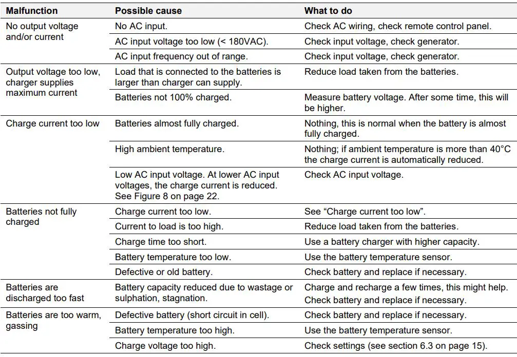
TROUBLE SHOOTING
In case of a failure, the Mass Charger display shows an error ‘code’ to help you find its source. See section 5.6 LED indicators, on page 14. If you cannot solve a problem using the following fault-finding table, contact your Mastervolt dealer. Make sure you have the part and serial number at hand (See section 1.4, on page 3).
TECHNICAL DATA
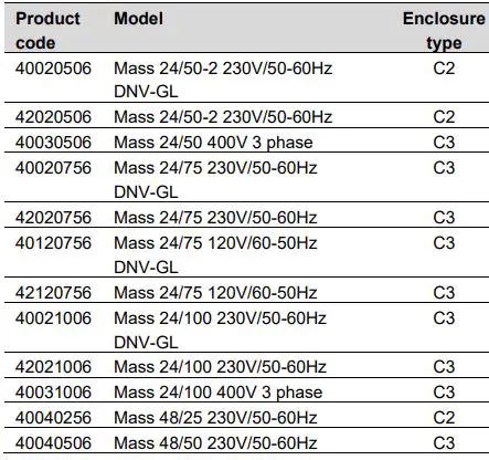
Specifications
| Model | Mass 24/50- 2 DNV-GL | Mass 24/50-2 | Mass 24/75 DNV-GL | Mass 24/75 | Mass 24/75 (120V) DNV-GL | Mass 24/75 (120V) |
| Product code | 40020506 | 42020506 | 40020756 | 42020756 | 40120756 | 42120756 |
| INPUT | ||||||
| Mains voltage | 230V, -10% + 15% | 230V, -10% + 15% | 120V, -10% + 15% | |||
| Frequency | 50-60Hz ± 5Hz | 50-60Hz ± 5Hz | 60-50Hz ± 5Hz | |||
| Inrush current | None, the battery charger is equipped with a soft start in accordance with IEC 1003-3 | |||||
| Input current | 7A | 12A | 25A | |||
| Power factor (Cos phi) | 1 | 1 | 1 | |||
| Maximum efficiency | 89% | 89% | 89% | |||
| Input power | 1600W | 2700W | 2700W | |||
| OUTPUT | ||||||
| Nominal voltage | 24VDC | 24VDC | 24VDC | |||
| Max charge current (Imax)* | 50A | 75A | 75A | |||
| Outputs | 1 x 50A + 1 x 3A | 1 x 75A | 1 x 75A | |||
| Charge characteristic* | 3-step+, fully automatic | |||||
| Battery types: | Flooded lead acid, Gel/AGM lead acid, NiCad, Lithium-ion (Mastervolt MLI) (see section 6.3 for settings) | |||||
| Default charge voltages at 25°C: | ||||||
| Absorption voltage* | 28.5V | 28.5V | 28.5V | |||
| Float voltage* | 26.5V | 26.5V | 26.5V | |||
| Voltage ripple | max. 100mV RMS with resistive load @ full power | |||||
| Short circuit current (1/4 of Imax) | 12.5A | 18.75A | 18.75A | |||
| Wire gauge (up to 3m length) | 25mm² | 25mm² | 25mm² | |||
| Charger fuse (external) | 63A | 80A | 80A | |||
| ENVIRONMENTAL | ||||||
| Ambient temperature | -20 to 40°C** @ 100% output power, derated with 2.5%/°C above 40°C | |||||
| Cooling | Forced air, by means of a ventilator with variable speed | |||||
| Humidity | Maximum 95%RV, non-condensing | |||||
| MASTERBUS | ||||||
| MasterBus powering capability | Yes | Yes | Yes | |||
| MasterBus menu languages | English, Dutch, German, French, Spanish, Italian | |||||
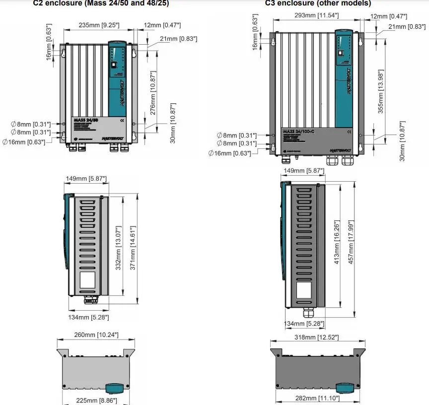
| ENCLOSURE TYPE | C2 | C3 | C3 | |||
| Dimensions (hxwxd)mm | See section 8.2 on page 21 | |||||
| Protection degree | IP23 | IP23 | IP23 | |||
| Weight | 5kg | 9kg | 9kg | |||
| COMPLIANCE | ||||||
| Standards, approvals & listings | CE, ABYC A-31, DNV GL, RRR, RMRS | CE, ABYC A-31, RRR, RMRS | CE, ABYC A-31, DNV GL, RRR, RMRS | CE, ABYC A-31, RRR, RMRS | CE, ABYC A-31, DNV GL, RRR, RMRS | CE, ABYC A-31, RRR, RMRS |
* Adjustable, see chapter 4.
** The Mass 24/50-2 allows operation in ambient temperatures as high as 45°C. Specifications are subject to change without prior notice.
| Model | Mass 24/100 DNV-GL | Mass 24/100 | Mass 24/50 3ph | Mass 24/100 3ph | Mass 48/25 | Mass 48/50 |
| Product code | 40021006 | 42021006 | 40030506 | 40031006 | 40040256 | 40040506 |
| INPUT | ||||||
| Mains voltage | 230V, -10% + 15% | 3 x 365…550V | 3 x 365…550V** | 230V, -10% + 15% | 230V, -10% + 15% | |
| Frequency | 50-60Hz ± 5Hz | 50-60Hz ± 5Hz | 50-60Hz ± 5Hz | 50-60Hz ± 5Hz | 50-60Hz ± 5Hz | |
| Inrush current | None, the battery charger is equipped with a soft start in accordance with IEC 1003-3 | |||||
| Current | 16A | 3.3A | 6.5A | 8A | 16A | |
| Power factor (Cos phi) | 1 | 0.8 | 0.8 | 1 | 1 | |
| Efficiency | 89% | 89% | 89% | 89% | 89% | |
| Input power | 3600W | 1750W | 3500W | 1800W | 3600W | |
| OUTPUT | ||||||
| Nominal voltage | 24VDC | 24VDC | 24VDC | 48VDC | 48VDC | |
| Max charge current (Imax)* | 100A | 50A | 100A | 25A | 50A | |
| Outputs | 1 x 100A | 1 x 50A | 1 x 100A | 1 x 25A | 1 x 50A | |
| Charge characteristic* | 3-step+, fully automatic | |||||
| Battery types: | Flooded lead acid, Gel/AGM lead acid, NiCad, Lithium-ion (Mastervolt MLI) (settings: section 7.10) | |||||
| Default charge voltages at 25°C: | ||||||
| Absorption voltage* | 28.5V | 28.5V | 28.5V | 57V | 57V | |
| Float voltage* | 26.5V | 26.5V | 26.5V | 53V | 53V | |
| Voltage ripple | max. 100mV RMS with resistive load @ full power | |||||
| Short circuit current (1/4 of Imax) | 25A | 12.5A | 25A | 6A | 12.5A | |
| Cable size (within 3 m) | 35mm² | 25mm² | 35mm² | 10mm² | 25mm² | |
| Charger fuse (external) | 125A | 63A | 125A | 32A | 63A | |
| ENVIRONMENTAL | ||||||
| Ambient temperature | -20 to 40°C @ 100% output power, derated with 2,5%/°C above 40°C | |||||
| Cooling | Forced air, by means of a ventilator with variable speed | |||||
| Humidity | Maximum 95%RV, non-condensing | |||||
| MASTERBUS | ||||||
| MasterBus powering capability | Yes | Yes | Yes | Yes | Yes | |
| MasterBus menu languages | English, Dutch, German, French, Spanish, Italian | |||||
| ENCLOSURE TYPE | C3 | C3 | C3 | C2 | C3 | |
| Dimensions (hxwxd)mm | See section 8.2 on page 21 | |||||
| Protection degree | IP23 | IP23 | IP23 | IP23 | IP23 | |
| Weight | 9kg | 10kg | 10kg | 5kg | 9kg | |
| COMPLIANCE | ||||||
| Standards, approvals & listings | CE, ABYC A-31, DNV GL, RRR, RMRS | CE, ABYC A-31, RRR, RMRS | CE, ABYC A-31, RRR, RMRS | CE, ABYC A-31, RRR, RMRS | CE, ABYC A-31, RRR, RMRS | CE, ABYC A-31, RRR, RMRS |
Adjustable, see chapter
For device versions up to J (see section 1.4 on page 3): 3x 365…440V Specifications are subject to change without prior notice.
Characteristics
Dimensions
 Characteristics
 Europe, Middle East & Africa Technical Support
T: +31 (0) 20 34 22 100
E: [email protected]
Location & Shipping
Navico Group EMEA
Snijdersbergweg 93
1105 AN Amsterdam
The Netherlands
Americas & Caribbean
Technical Support
T: +1 262 293 0600 / 800 307 6702
E: [email protected]
Location & Shipping
Navico Group US
N85 W12545 Westbrook Crossing
Menomonee Falls, WI 53051
United States
Asia Pacific
Technical Support
T: +64 9 415 7261
E: [email protected]
Location & Shipping
Navico Group APAC
42 Apollo Drive
Rosedale, Auckland 0632
New Zealand
Document version: 10000001888/03 (December 22) Copyright ©2022 Navico Group EMEA B.V. All rights reserved.


