
SmartGen BACM2420A Battery
OVERVIEW
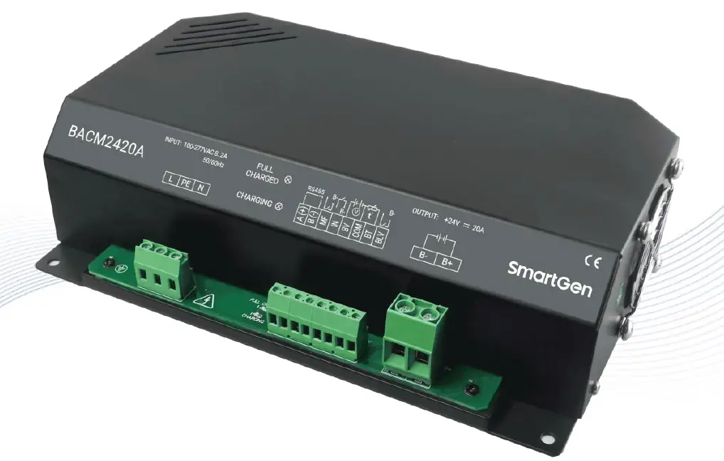
BACM2420A battery charger is an intelligent and multi-function charger, which is specially designed to meet the charging characteristics of the lead-acid engine starter batteries. It is suitable for 24V or 12V battery pack and the maximum output current is 20A.
PERFORMANCE AND CHARACTERISTICS
It has the following characteristics:
- Switch power supply structure, wide AC voltage input range, small size, light weight, high efficiency;
- Users can select automatic two-stage charging process or automatic three-stage charging process according to needs. Both two charging processes are carried out according to storage battery charging characteristics, which can prevent overcharging and significantly prolong battery lifetime;
- Built-in PFC circuit, which allows to calibrate the power factor up to 0.99;
- Battery voltage detection ports, which can detect the battery voltage at real time.
- Battery under voltage output port; it will output low level immediately after the battery voltage has fallen below the set value after preset delay.
- Temperature sensor port, which allows monitoring the battery temperature at real time; and temperature compensation function, which can prevent too high battery temperature effectively;
- Mains failure alarm port; It will output low level when the AC input is interrupted;
- Standard RS485 serial communication port.
- Default suitable for 24V battery pack; it can be changed to 12V battery pack by changing configuration information; rated charging current is 20A;
- External LED status display: Full charged indication (Green light) and charging indication (Red light).
CHARGING PRINCIPLE
Fig. 1 Three-stage Charging Curve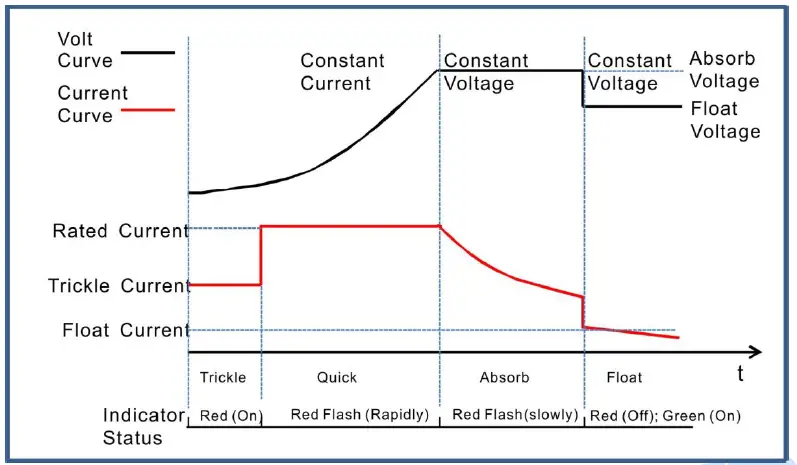 Three-stage charging method is used according to the battery charging characteristics.
- The first stage is named “constant current”. a): Trickle Charge: when the battery terminal voltage is relatively low, the charging current is low likewise, which effectively prevents battery damage from too high temperature. The charging indicator (Red color) status is illuminated. b): Quick Charge: When the battery terminal voltage is relatively high, the charging current will rise to rated value. Large current charging operation leads to a rapid increase in the electrical quantity of the battery. The charging indicator (Red color) status is flashing rapidly (0.2s/per).
- The second stage is named “absorption charge”. After the first stage, the battery voltage rises to absorption charge value rapidly, and the charger voltage will keep constant. The battery terminal voltage will stabilize in the absorption charge value with the decreasing of charging current. The charging indicator (Red color) status is flashing slowly (1s/per).
- The third stage is named “float charge”: After the above two stages, the charging is basically completed and charger output voltage changes to float voltage automatically. Charging current decreases to floating charging current. Red charging indication is extinguished. Green full charging indication is illuminated. Afterwards charging current neutralizes self-discharge of the battery. Even long-term charging doesn’t do harm to the battery. That is, charger not only can keep the battery fully charged but also guarantee long lifetime of the battery.
Fig. 2 Two-stage Charging Curve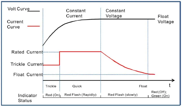 Two-stage charging method is performed according to the battery charging characteristics.
- The first stage is named “constant current”. a): Trickle Charge: when the battery terminal voltage is relatively low, the charging current is low likewise, which can prevent battery damage from too high temperature. The charging indicator (Red color) status is illuminated. b): Quick Charge: When the battery terminal voltage is relatively high, the charging current will rise to rated value. Large current charging operation leads to a rapid increase in the electrical quantity of the battery. The charging indicator (Red color) status is flashing rapidly (0.2s/per).
- The second stage is named “float charge”. The charging current will decrease with the rising of battery electricity. The charging indicator (Red color) status is flashing slowly (1s/per). As soon as charging current value falls below 0.3A, the battery is basically fully charged (Red indicator will extinguish and the green indicator will be illuminated). After that charging current will only neutralize the battery self-discharge. Even long-term charging cannot harm the battery, as charger can keep the battery fully charged and also guarantee long lifetime of the battery.
Table 2 Charging Indicator Status
| Mode | Indicator | Charging Status | ||||
| Constant Current | Constant Voltage | Float Charge | Charge Failure | |||
| Trickle Charge | Quick Charge | |||||
| Two Stage | Red | On | Flash(Rapidly) | None | Flash(Slowly)→Off | Flash(Rapidly) |
| Green | Off | Off | None | Off→On | Flash(Rapidly) | |
| Three Stage | Red | On | Flash(Rapidly) | Flash(Slowly) | Off | Flash(Rapidly) |
| Green | Off | Off | Off | On | Flash(Rapidly) | |
PARAMETERS CONFIGURATION
Table 3 Parameter Configuration List
| Items | Default | Adjustable Range | Description | ||
| 24V | 12V | 24V | 12V | ||
| Battery Type | 1 | (0~2) | 0:12V;1:24V;2:Self-adaption | ||
| Charging Stage | 3 | (2~3) | 2: Two Stage; 3: Three Stage | ||
| Max. Rated Current | 20.0A | Nonadjustable | Maximum charging current | ||
| Rated Current | 100% | (0~100)% | Maximum charging current percentage | ||
| Absorption Charge Voltage | 28.2V | 14.1V | (20~32)V | (10~16)V | The charging voltage of “Constant Voltage” |
| Absorption Charge Time | 1 | (0~1) | 0: Disable; 1: Enable | ||
| Absorption Charge Time Setting | 1.0h | (0.1~100)h | The charging time of “Constant Voltage” | ||
| Absorption Charge Complete Current | 1 | (0~1) | 0: Disable; 1: Enable | ||
| Complete Current Setting | 0.5A | (0.20~3.00)A | The transition current from “Absorption Charge” transfer to “Float Charge”. | ||
| Float Charge Voltage | 27.0V | 13.5V | (20~32)V | (10~16)V | The voltage of “Float Charge” |
| AUTO BOOST Voltage | 25.6V | 12.8V | (20~32)V | (10~16)V | When the charger is in “Float Mode”, it enters into “Quick Charge” if the battery voltage has fallen below the set value. |
| Trickle Charge | 1 | (0~1) | 0: Disable; 1: Enable | ||
| Trickle Charge Voltage | 22.0V | 11.0V | (20~32)V | (10~16)V | The voltage of “Trickle Charge” |
| Trickle Charge Current | 50% | (0~100)% | Maximum charging current percentage | ||
| Battery Detection | 0 | (0~1) | 0: Disable; 1: Enable | ||
| Battery Under Voltage Warn | 1 | (0~1) | 0: Disable; 1: Enable | ||
| Under Voltage Set Value | 23.0V | 11.50V | (16.0~32.0)V | (8.0~16.0)V | “Under voltage” alarm will be initiated if the battery voltage has fallen below the set value. |
| Under Voltage Delay |
120s |
(0~3600)s | “Under voltage” alarm will be initiated if the battery voltage has fallen below the set value and the delay timer has expired. | ||
| Under Voltage Return Value | 24.0V | 12.0V | (16.0~32.0)V | (8.0~16.0)V | The transition voltage from “under voltage” transfer to “normal voltage”. |
| Under Voltage Return Delay |
10s |
(0~3600)s | “Under voltage” alarm will be removed if the battery voltage has exceeded the return value and the delay timer has expired. | ||
| Temperature | 1 | (0~1) | 0: Disable; 1: Enable | ||
| Items | Default | Adjustable Range | Description | ||
| 24V | 12V | 24V | 12V | ||
| Sensor | |||||
| Temperature Compensation | 1 | (0~1) | 0: Disable; 1: Enable | ||
| Temperature Compensation Set Value | 0.036 V/℃ | 0.018 V/℃ | (0.020~0.060) V/℃ | (0.010~0.030) V/℃ | The Compensation of each 1℃ change on 20℃ basis. |
| High Temp. Warn | 1 | (0~1) | 0: Disable; 1: Enable | ||
| High Temp. Set Value | 55℃ | (0~80)℃ | “High Temp.” alarm will be initiated if the battery temperature has exceeded the set value. | ||
| High Temp. Delay |
0.5s |
(0~60.0)s | “High Temp.” alarm will be initiated if the battery temperature has exceeded the set value and the delay timer has expired. | ||
| High Temp. Return Value | 50℃ | (0~80)℃ | The transition temperature from “High Temp.” transfer to “Normal Temp.”. | ||
| High Temp. Return Delay |
1s |
(0~60.0)s | “High Temp.” alarm will be removed if the battery temperature has fallen below the return value and the delay timer has expired. | ||
| Aux. Input Port | 3 | (0~4) |
| ||
| Aux. Input Port Delay | 2.0s | (0~60.0)s | The corresponding action will be active if the input is active. | ||
| Communication Address | 10 | 1~254 | RS485 Communication Address | ||
| Baud Rate | 0 | (0~2) |
| ||
PARAMETERS SPECIFICATION
Table 4 Product Parameters
| Items | Contents | Parameters | |||
| 24V | 12V | ||||
|
Input Characteristics | Nominal AC Voltage Range | AC (100~277)V | |||
| Max. AC Voltage Range | AC (90~305)V | ||||
| AC Frequency | 50Hz/60Hz | ||||
| Max. Active Power | 736W | 373W | |||
| Max. Current | 8.2A | 4.2A | |||
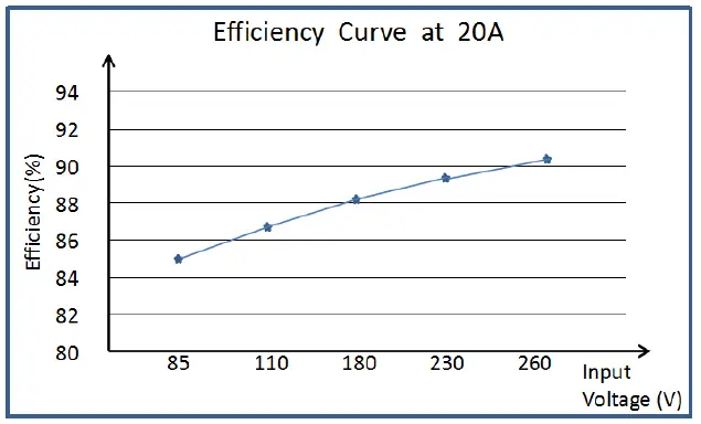
| Max. Efficiency | 90% | 85% | |||
| Power Factor Calibration | AC 110V | AC 220V | AC 110V | AC 220V | |
| >0.99 | >0.97 | >0.99 | >0.97 | ||
|
Output Characteristics | No-load Output Voltage | 32V,Error±1% | 16V, Error±1% | ||
| Rated Charging Current | 20A,Error±2% | ||||
| Max. Output Power | 640W | 320W | |||
|
Insulating Property | Insulation Resistance | Between input and output, input and shell all are DC1000V1min, insulation resistance RL≧50MΩ | |||
| Insulation Voltage | Between input and output, input and shell all are: AC3000V 50Hz 1min, leakage current: IL≦3mA Between output and shell is: AC500V 50Hz 1min leakage current: IL≦3mA | ||||
|
Working Condition | Working Temperature | (-30~+55)°C | |||
| Storage Temperature | (-40~+85)°C | ||||
| Working Humidity | 20%RH~93%RH(No condensation) | ||||
| Shape Structure | Weight | 2.2kg | |||
| Dimension | 265mm×156mm×68mm (length*width*height) | ||||
Fig. 3 Efficiency Curve
OPERATION
Fig. 4 BACM2420A Mask Table 5 Wiring Connections
| Terminal | Function | Description |
| L | AC Input Terminals | Connect terminals L and N to AC (100~277)V; Bigger than BVR 2.0mm2 multi-strand copper line is recommended. |
| N | ||
| PE | GND Terminals | Connect to shell internally. |
| A(+) | RS485 Communication Port | Standard RS485 serial communication interface |
| B(-) | ||
| MF | Mains Failure Output Port | It will output low level immediately when the AC input is interrupted. |
| IN | Auxiliary input port | Low level is active. |
| BV | Battery Voltage Port | Connect to battery positive. |
| COM | Common Port | COM port of BV and temperature acquisition terminal. Connect to battery negative. |
| BT | Temperature Sensor Port | Connect to PT1000 sensor |
| BLV | Battery Low Voltage Alarm Output Port | It will output low level when the battery voltage has fallen below the set value. |
| B- | Battery Negative | Connect to battery negative; Bigger than BVR 4mm2 multi-strand copper line is recommended. |
| B+ | Battery Positive | Connect to battery positive; Bigger than BVR 4mm2 multi-strand copper line is recommended. |
| FULL CHARGED | Green LED Indicator | Full charged indicator. |
| CHARGING | Red LED Indicator | Charging status indicator. |
NOTE
- Because there is diode and current-limiting circuit inner the charger, it can be used together with charging generator, and there is no need to disconnect the charger when cranking.
- During genset is running, high current will cause voltage drop in charging line, so recommend separately connecting to battery terminal to avoid disturbance on sampling precision.
CONNECTION
Fig. 5 Wiring Diagram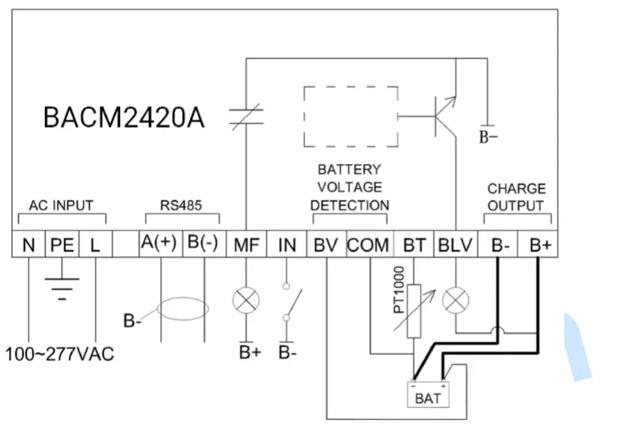
CASE DIMENSIONS
Fig. 6 BACM2420A Installation Size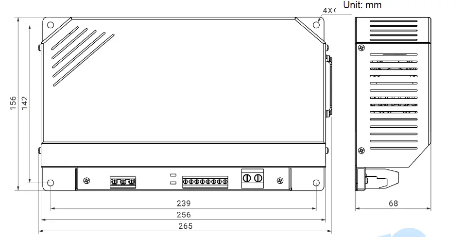
SmartGen — make your generator smart
SmartGen Technology Co., Ltd.
No.28 Jinsuo Road, Zhengzhou, Henan Province, China
Tel: +86-371-67988888/67981888/67992951
+86-371-67981000(overseas)
Fax: +86-371-67992952
Email: [email protected]
Web: www.smartgen.com.cn
www.smartgen.cn
All rights reserved. No part of this publication may be reproduced in any material form (including photocopying or storing in any medium by electronic means or other) without the written permission of the copyright holder.
Applications for the copyright holder’s written permission to reproduce any part of this publication should be addressed to Smartgen Technology at the address above.
Any reference to trademarked product names used within this publication is owned by their respective companies.
SmartGen Technology reserves the right to change the contents of this document without prior notice.
Software Version
| Date | Version | Note |
| 2021-03-29 | 1.0 | Original Release |
| 2022-04-22 | 1.1 | Modify the parameter of wiring connections. |


