SmartGen BAC06NB Series Battery Charger
All rights reserved. No part of this publication may be reproduced in any material form (including photocopying or storing in any medium by electronic means or other) without the written permission of the copyright holder.
Applications for the copyright holder’s written permission to reproduce any part of this publication should be addressed to Smartgen Technology at the address above. Any reference to trademarked product names used within this publication is owned by their respective companies.
SmartGen Technology reserves the right to change the contents of this document without prior notice.
Table 1 Software Version
Date | Version | Note |
| 2020-05-09 | 1.0 | Original release. |
| 2020-10-12 | 1.1 | Added the model BAC06NB. |
| 2022-07-25 | 1.2 | Updated the manual format; updated the logo of SmartGen. |
OVERVIEW
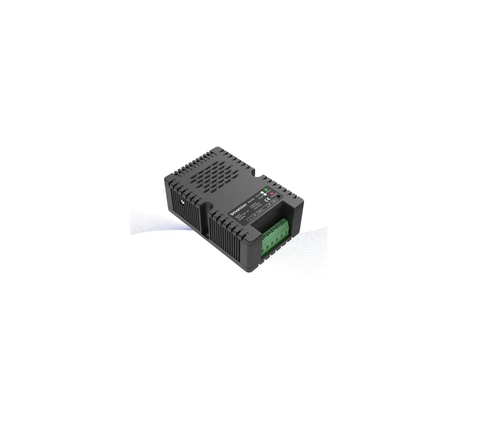
BAC06N/BAC06NB series battery chargers adopt switching power supply device, and is specially designed for lead-acid battery used in engine start according to its property. The charger is suitable for long-term complement charging (floating) of lead-acid battery. The maximum output current for 12V charger is 6A; the maximum output current for 24V charger is 3A.
PERFORMANCE AND CHARACTERISTICS
Characteristics are as below:
- Applying switching power supply structure, wide range of AC voltage input, small volume, light weight and high efficiency;
- BAC06N adopts two-stage charging method for automatic charging, BAC06NB can be automatically charged by selecting two-stage or three-stage charging method based on needs, both of them are designed according to charging properties of the lead-acid battery, which can avoid overcharging and this extends the battery life to the fullest;
- BAC06N has short circuit protection, reverse connection protection; while BAC06NB has short circuit protection, reverse connection protection, absorption timing, and BOOST functions;
- LED status display: power indicator, and charging indicator;
- Applying horizontal installation, which is easy and simple to install.
CHARGING PRINCIPLES
TWO-STAGE CHARGING PRINCIPLE
Fig. 1 Two Stage Charging Principle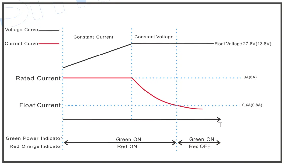
According to battery charging properties to conduct charging, if two-stage charging method is used, charging mode is “constant voltage/constant current mode”. That is, before battery terminal voltage is lower than pre-set value, it is constant current charging, and current is 3A (6A). When battery terminal voltage is higher than the pre-set value, charging current decreases gradually as battery terminal voltage increases until it reaches pre-set current value. At this time it turns to float mode and charging current reduces gradually. Battery terminal voltage also gradually increases to pre-set constant voltage value. Charging current is less than 0.4A (0.8A) and battery is basically full-charged (charge indicator is OFF). Afterwards charging current only offsets the self-discharging of battery and even long-term charging does no harm for the battery, that is, charger can not only maintain battery full-status, but also ensure the usage life of battery.
THREE-STAGE CHARGING PRINCIPLE
Fig. 2 Three Stage Charging Principle
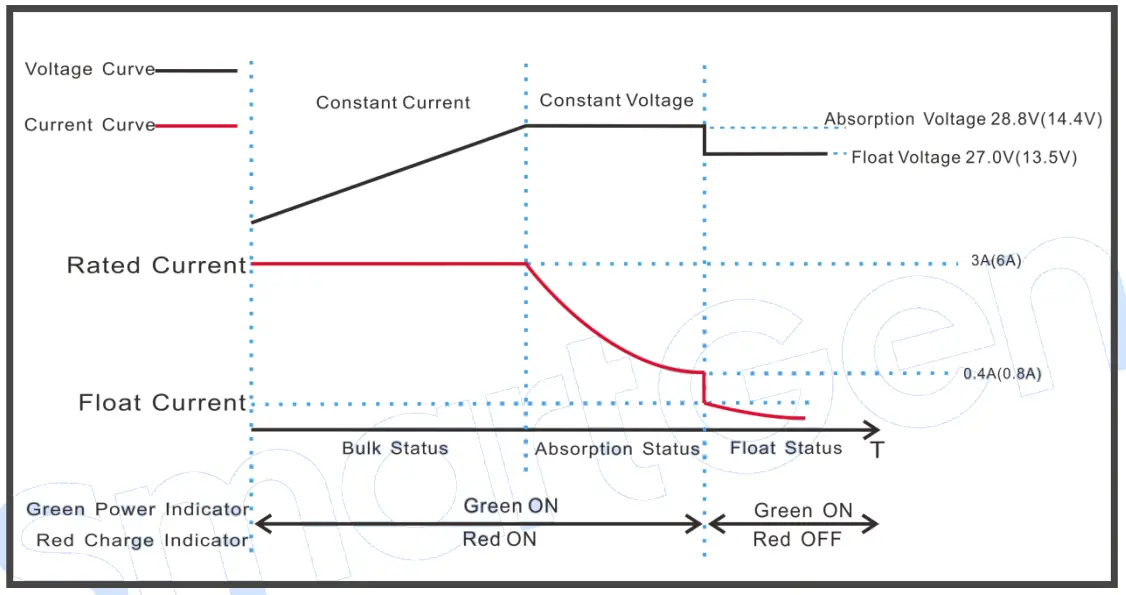
According to battery charging properties to conduct charging three-stage charging method is used.
- Charging mode of first phase is “constant current mode”. When battery terminal voltage is low, charging current is rated 3A (6A). Large current makes battery power rise rapidly. Above process is called bulk charging. Its characteristics is red charging indicator ON always.
- Charging mode of second phase is “absorption mode”. After constant current charging, battery voltage rises to absorption voltage value. At this time battery keeps constant voltage output and charging current decreases slowly. Battery terminal voltage then keeps slowly at absorption voltage value. In this process red charging indicator is ON always. When absorption mode is reached, internal timer starts counting. When charging current drops to below 0.4A (0.8A), or about 3.5 hours, it turns to float charging mode.
- Charging mode of third phase is “float mode”. After above two modes, power is basically full, and charger output voltage automatically transfers to float voltage 27.0V (13.5V), while current drops to below 0.4A (0.8A). Red charging indicator is OFF.
When charging current is above 2.6A (5.2A), charger enters absorption mode.
SPECIFICATION
Table 2 Product Parameters
| Category | Items | BAC06N | BAC06NB | ||||
| Two-stage | Two-stage | Three-stage | Two-stage | Three-stage | |||
| 12V | 24V | 12V | 12V | 24V | 24V | ||
|
Input Characteri stics | Nominal AC Voltage | AC (100~277)V | |||||
| Max. AC Voltage | AC (95~305)V | ||||||
| AC Frequency | 50Hz/60Hz | ||||||
| Max. Input Current | 2A | ||||||
| Max. Efficiency | 85% | 87% | 85% | 87% | |||
| Output Characteri stics | Rated Current | 6A | 3A | 6A | 3A | ||
| Float Voltage | 13.8V | 27.6V | 13.8V | 13.5V | 27.6V | 27.0V | |
| Absorption Voltage | / | / | / | 14.4V | / | 28.8V | |
| Max. Output Power | 82W | 82W | 82W | 87W | 82W | 87W | |
| No-load power consumption | <3W | ||||||
| Insulation | Insulation Resistance | Between input and output, input and shell, input and BOOST all are: DC500V 1min R≥500MΩ | |||||
| Insulation Voltage | Between input and output, input and shell, input and BOOST all are: DC4200V 1min, between output and shell it is DC800V 1min, Leakage current: I≤3.5mA. | ||||||
| Working Conditions | Working Temperature | (-30~+55)°C | |||||
| Storage Temperature | (-40~+85)°C | ||||||
| Working Humidity | 20%RH~93%RH (No condensation) | ||||||
| EMC | EMC Emission | EN55032 | |||||
| EMC Immunity | IEC/EN61000-4-2,3,4 ,5,6,11 GB17626.2,3,4,5,6,11 | ||||||
| Profile | Weight | 0.47kg | |||||
| Dimension | 136mm×86mm×49mm | ||||||
| Mounting Size | Screw Mounting | Hole centers 77mm, suitable for M4; | |||||
OPERATION
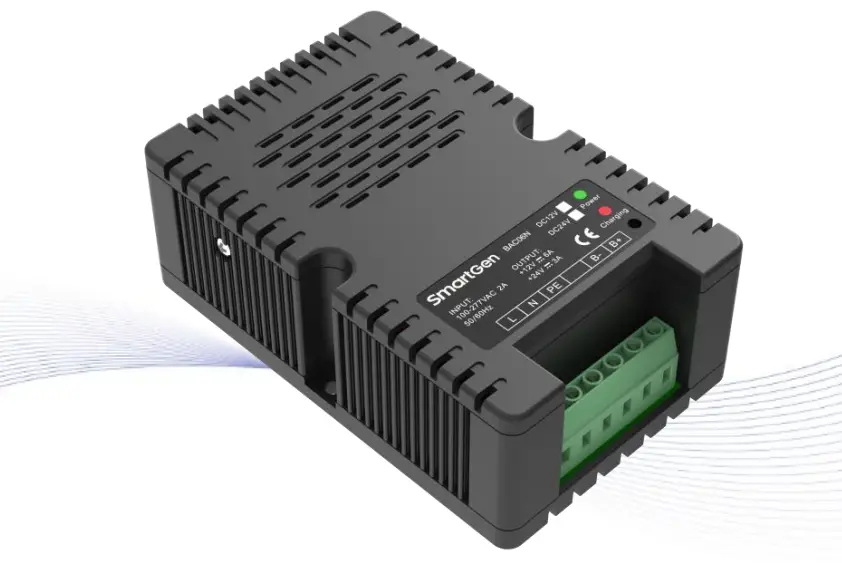
Fig. 3 Panels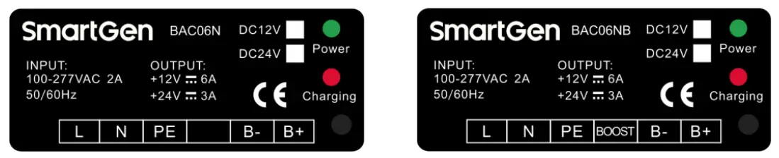
Table 3 Operation Illustration
| Mark | Function | Description |
| L | AC input terminal | Terminal L and N connects AC (100-277)V; BVR1mm2 multi-strand copper line is recommended. |
| N | ||
| PE | GND connected terminal | Internally connected with shell; |
| BOOST | BAC06NB Charging phase mode | Two-stage: BOOST hung up; Three-stage: BOOST verse B- short circuit connection; |
| B- | Charger output negative | Connected with battery negative; BVR1.5mm2 multi-strand copper line is recommended. |
| B+ | Charger output positive | Connected with battery positive; BVR1.5mm2 multi-strand copper line is recommended. |
| Power | Green LED indicator | Power status indicator; |
| Charging | Red LED indicator | Charging status indicator. |
NOTE 1: Charger can be used with charger in the engine in parallel and there is no need to disconnect charger at cranking.
NOTE 2: For application on genset, as charging current is very big and voltage drop will produce from charging wires, so it is recommended to connect charging wire to battery terminal separately. The purpose of this is to avoid affecting sensor sampling precision.
WIRING DIAGRAM
Fig. 4 BAC06N Wiring Diagram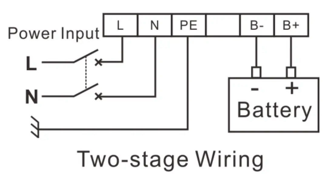
Fig. 4 BAC06NB Wiring Diagram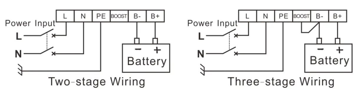
OVERALL DIMENSIONS AND INSTALLATION SIZE
Fig. 6 Installation Size Drawing Unit: mm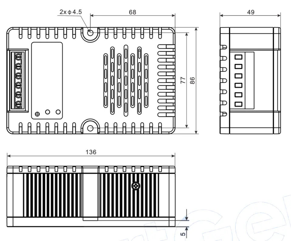
NOTE 1: This charger is screw mounting designed, please use 2 pieces of M4 slots to fix.
MODELS
For ordering, please select based on the table below
Table 4 Charger Mode
| Model | Battery Type | Rated Output Current | BOOST Function |
| BAC06N-12V | 12V | 6A | |
| BAC06N-24V | 24V | 3A | |
| BAC06NB-12V | 12V | 6A | · |
| BAC06NB-24V | 24V | 3A | · |
Customer Support
No.28 Jinsuo Road, Zhengzhou, Henan Province, China
Tel: +86-371-67988888/67981888/67992951
+86-371-67981000(overseas)
Fax: +86-371-67992952
Email: [email protected]
Web: www.smartgen.com.cn
www.smartgen.cn