![]() ASSA ABLOY
ASSA ABLOY
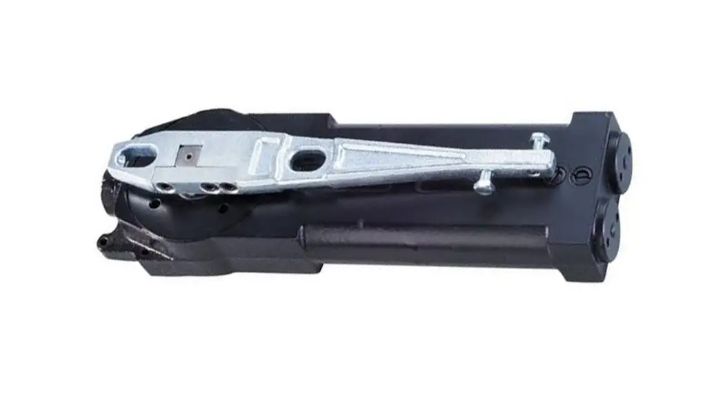
LOCKWOOD 9800 SERIES CONCEALED
OVERHEAD DOOR CLOSER
TIMBER DOOR INSTALLATION INSTRUCTION
CENTRE PIVOTED – DOUBLE OR SINGLE-ACTING DOORS
NOTE: ALL DIMENSIONS ARE BASED ONA 70mm PIVOT POSITION MINIMUM DOOR THICKNESS 38mm 8
 Unit:mm
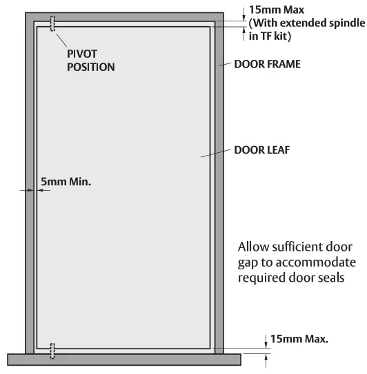
DOOR GAP ALLOWANCE
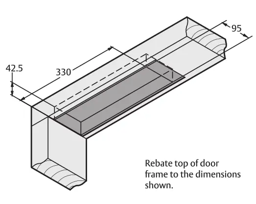
DOOR HEADER PREPARATION
TOP DOOR RAIL (SIDE LOADING ARM)
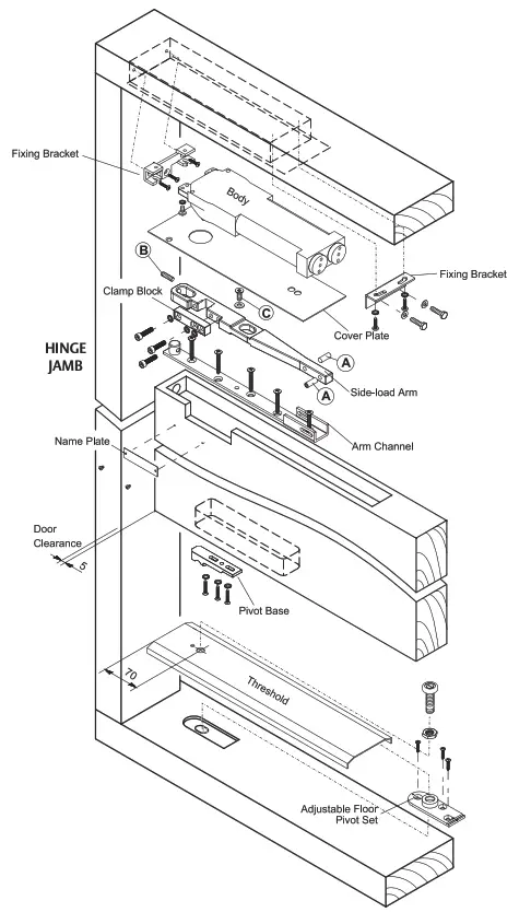
Make 60 x 15mm cut out in the top of the door as shown. The cut must be on the inside face of the door.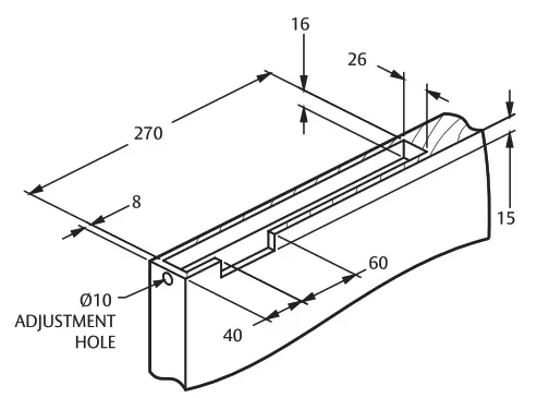 Fix arm channel with #10 x 30 flat head screws and install arm using M6 x 15 flat head machine screw and @21.5 washer. Install M6 x 25 dome head arm adjustment screw. Laterally adjust the center of the arm spindle retainer from the outside edge of the door (not including weather strips).
Center arm in the top rail by adjusting the three 1/4″ x 22 flat head machine screw centering bolts. After installation of the door, attach the cover plate with self-tapping screw as provided.
NOTE: Before attaching the cover plate, make certain the three 1/4” x 22 socket head clamp block cap screws are tightened securely. 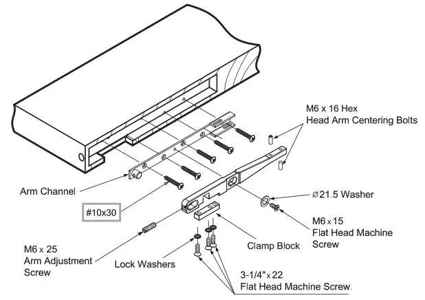
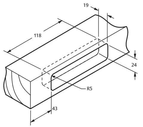
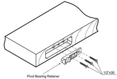
BOTTOM DOOR RAIL (SIDE LOADING)
Rebate the bottom of the door to the dimensions shown.
Install pivot bearing retainer in the bottom of the door using three 1/2″ x 30 screws and lock washers. Laterally adjust the center of pivot bearing retainer from the outside edge of door (not including weather-strips) and tighten screws firmly.
INSTALLATION OF BODY INTO DOOR HEADER
Secure Fixing Bracket (A) into the door frame rebate.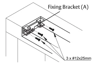 Secure Fixing Bracket (B) to the back of the door closer body.
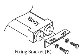 Mount the door closer body into the Fixing Bracket (A) then screw Fixing Bracket (B) into the door frame.
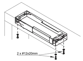
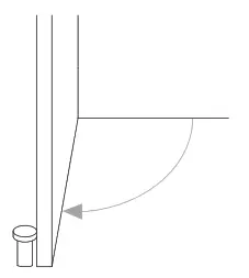
FLOOR MOUNT PIVOT
Center pivot base against the door jamb on the hinge side. Mark and drill ©8 holes 40 deep in floor top plastic expansion plugs. Mount base using @8 x 40 plastic expansion plugs and #12 x 25 flat head tapping screws.
ATTENTION: The floor mount pivot base should be fixed on the completely flat floor surface. If the floor surface is not flat, make it flat before fixing the floor mount pivot base.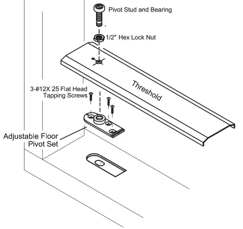
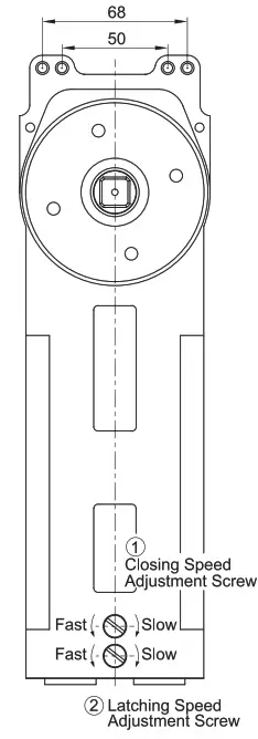
SPEED ADJUSTMENT
Turn adjustment screw ‘1 for desired closing speed then turn adjustment screw ‘2! to produce a suitable latching speed.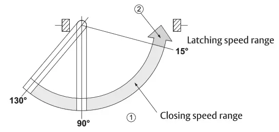
PARALLEL DOOR POSITION ADJUSTMENT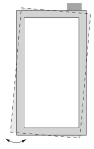 Clearance adjustable by screw (8) after loosening screw ©.
CLOSED POSITION ADJUSTMENT DOOR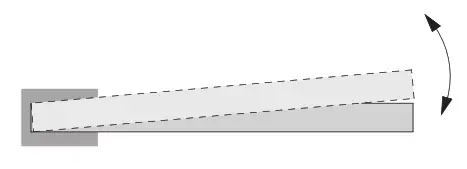
Closing position adjustable by screw A’ after loosening screw ©.
ATTENTION
Opening the door wider than 90° (130°) capacity will seriously damage the closer.
An Adoor stopper at the point of 90° fi (130°) is recommended to prevent the door from opening wider.
 ASSA ABLOY Australia Pty Limited, 235 Huntingdale Rd, Oakleigh,
VIC 3166 ABN 90 086 451 907 ©2022
Experience a safer and more open world


