 STMicroelectronics UM2866 X-NUCLEO-OUT06A1 Industrial Digital Output Expansion Board
Getting started with X-NUCLEO-OUT06A1 industrial digital output expansion board for STM32 Nucleo
Introduction
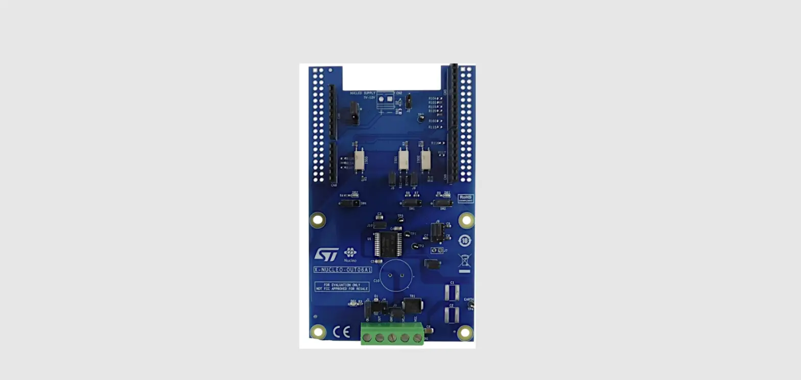
The X-NUCLEO-OUT06A1 industrial digital output expansion board for STM32 Nucleo provides a powerful and flexible environment for the evaluation of the driving and diagnostic capabilities of the IPS1025H-32 single high-side smart power solid state relay, in a digital output module connected to 5.7 A industrial loads.
The X-NUCLEO-OUT06A1 interfaces with the microcontroller on the STM32 Nucleo via 5 kV optocouplers driven by GPIO pins and Arduino UNO R3 connectors.
The expansion board can be connected to either a NUCLEO-F401RE or NUCLEO-G431RB development board.
It is also possible to evaluate a system composed by up to four stacked X-NUCLEO-OUT06A1 expansion boards.
As an example, a system with four X-NUCLEO-OUT06A1 expansion boards allows you to evaluate a quad channel digital output module.
Figure 1. X-NUCLEO-OUT06A1 expansion board
Overview
The X-NUCLEO-OUT06A1 embeds the IPS1025H-32 intelligent power switch (IPS), featuring overcurrent and overtemperature protection for safe output load control.
The board is designed to meet application requirements in terms of galvanic isolation between user and power interfaces. This requirement is satisfied by an optical isolation implemented through three optocouplers (ISO1, ISO2, and ISO3) for signal forward to the device and FLT pins for feedback diagnostic signals.
The expansion board features:
- Based on IPS1025H-32 single high-side switch, which features:
- Operating range up to 60 V
- Low power dissipation (RON(MAX) = 25 mΩ)
- Fast decay for inductive loads
- Smart driving of capacitive load
- Under-voltage lock-out
- Overload and over-temperature protection
- PSSO24 package
- Application board operating range: 8 to 33 V/0 to 5.7 A
- Extended voltage operating range (J3 open) up to 60 V
- Green LED for output on/off status
- Red LEDs for diagnostics (overload and overheating)
- 5 kV galvanic isolation Supply rail reverse polarity protection
- EMC compliance with IEC61000-4-2, IEC61000-4-3, IEC61000-4-4, IEC61000-4-5, IEC61000-4-8
- Compatible with STM32 Nucleo development boards
- Equipped with Arduino UNO R3 connectors
- CE certified:
- EN 55032:2015 + A1:2020
- EN 55035:2017 + A11:2020
- RoHS and China RoHS compliant
Digital section
The digital section is associated with the STM32 interface and digital supply voltage to and from the X-NUCLEO-OUT06A1 expansion board.
Figure 2. X-NUCLEO-OUT06A1 expansion board: digital interface section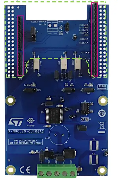
The dotted green line indicates the whole digital interface section. Pink rectangles identify Arduino UNO R3 connectors.
The four Arduino UNO R3 connectors:
- allow expansion board communication with the STM32 Nucleo development board microcontroller accessing STM32 peripheral and GPIO resources;
- provide digital supply voltage between the STM32 Nucleo development board and the X-NUCLEO-OUT06A1 expansion board, in either direction.Normally, the STM32 Nucleo development board supplies the expansion board by a 3v3 or 5v0 generated by the USB. You can select the preferred voltage on the expansion board via SW3 (3v3 closing pins 1-2; 5v0 closing pins 2-3).
Alternatively, it is possible to supply the STM32 Nucleo development board by the expansion board. In this case, an external supply voltage (7-12 V) should be connected to the CN2 connector (not mounted by default) on the expansion board and the ground loop should be closed by mounting D2 (enabling the reverse polarity protection) or by closing J2 (without reverse polarity).
To supply the VIN voltage rail, it is necessary to: - close jumper JP5 between pins 2 and 3 and open jumper JP1 on the NUCLEO-F401RE;
- open jumper JP5 between pins 1 and 2 and close jumper JP5 between pins 3 and 4 on the NUCLEO-G431RB.
Power section
The power section involves the power supply voltage (CN1, pins 4 and 5 for VCC, pin 3 for GND), load connection (a load can be connected between pins CN1.1 and CN1.3 or CN1.2 and CN1.3; both output pins are connected to the single output channel as shown in Section 2 Schematic diagrams) and electromagnetic compatibility (EMC) protection.
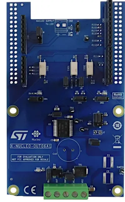
Figure 3. X-NUCLEO-OUT06A1 expansion board: power section components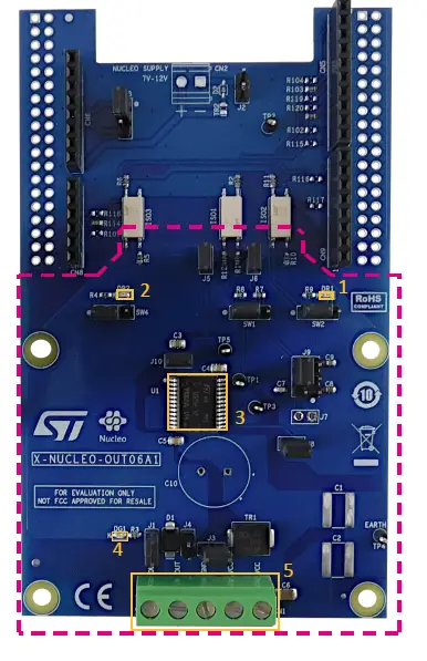
- Overtemperature red LED
- Overload red LED
- IPS1025H-32
- Output channel – green LED
- Output and power supply connector
For EMC
- The SM15T39CA transient voltage suppressor (TR1), enabled by closing J3, is placed between VCC and GND tracks to protect the IPS1025H-32 against surge discharge on the supply rail path up to ±1 kV/2 Ω coupling;
- in common mode surge testing, two single-layer capacitors (C1 and C2 – not included) must be soldered at the predisposed locations;
- the IPS1025H-32 output stages do not require additional EMC protections with respect to the IEC61000-4-2, IEC61000-4-3, IEC61000-4-4, IEC61000-4-5, IEC61000-4-8 standards.
Hardware requirements
The X-NUCLEO-OUT06A1 expansion board is designed to be used with the NUCLEO-F401RE or NUCLEO-G431RB STM32 Nucleo development boards.
To function correctly, the X-NUCLEO-OUT06A1 must be plugged onto the matching Arduino UNO R3 connector pins on the STM32 Nucleo board as shown below.
Figure 4. X-NUCLEO-OUT06A1 and STM32 Nucleo stack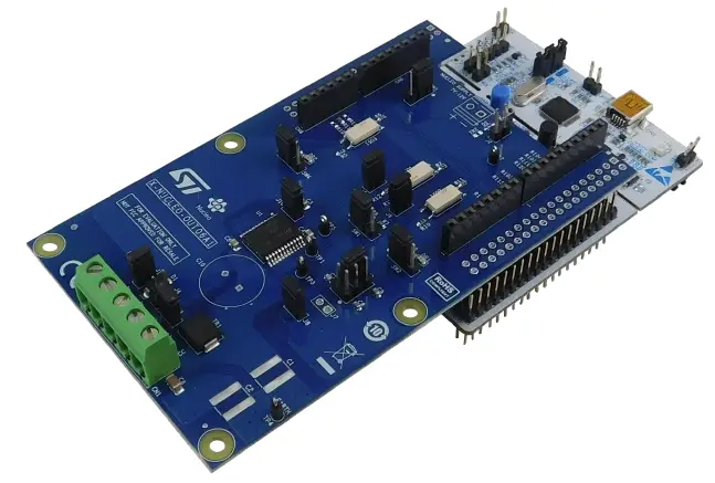
System requirements
To use the STM32 Nucleo development boards with the X-NUCLEO-OUT06A1 expansion board, you need:
- Windows PC/laptop (Windows 7 or above)
- type A to mini-B USB cable to connect the STM32 Nucleo board to the PC when using a NUCLEO-F401RE development board
- type A to micro-B USB cable to connect the STM32 Nucleo board to the PC when using a NUCLEO-G431RB development board
- the X-CUBE-OUT5 firmware and software package installed on your PC/laptop
Board setup
- Step. Connect the micro-USB or mini/USB cable to your PC to use the X-NUCLEO-OUT06A1 with NUCLEO-F401RE or NUCLEO-G431RB development board
- Step. Download the firmware (.bin) onto the STM32 Nucleo development board microcontroller through STM32 ST-LINK utility, STM32CubeProgrammer and according to your IDE environment as detailed in the table below.
Table 1. NUCLEO-F401RE development board supported IDEs – bin files
| NUCLEO-F401RE | ||
| IAR | Keil | STM32CubeIDE |
| EWARM-OUT05_06- STM32F4xx_Nucleo.bin | MDK-ARM-OUT05_06- STM32F4xx_Nucleo.bin | STM32CubeIDE-OUT05_06- STM32F4xx_Nucleo.bin |
Table 2. NUCLEO-G431RB development board supported IDEs – bin files
| NUCLEO-G431RB | ||
| IAR | Keil | STM32CubeIDE |
| EWARM-OUT05_06- STM32G4xx_Nucleo.bin | MDK-ARM-OUT05_06- STM32G4xx_Nucleo.bin | STM32CubeIDE-OUT05_06- STM32G4xx_Nucleo.bin
|
Step 3.Connect the IPS1025H-32 device supply voltage via CN1 (see Section 1.1.2 Power section).
Step 4. Provide the digital supply voltage (see Section 1.1.1 Digital section).
Step 5. Connect the load on the output connector (see Section 1.1.2 Power section).
Step 6. Reset the example sequence using the black push button.
Step 7. Push the STM32 Nucleo blue button to select the example provided in the firmware package.
Multiple board configuration
It is also possible to evaluate a four channel digital output module by stacking four X-NUCLEO-OUT06A1 with shared or independent supply rail and independent loads.
In this case, the four expansion boards (board 0, 1, 2, 3 as shown in the table below) must be properly configured: for board 1, 2 and 3, it is necessary to unsolder three resistors for each board from the default position and solder them back in the alternate positions according to the following table.
Table 3. Configuration of a stack of four expansion boards
| Board no. | IN1 | FLT1 | FLT2 |
| Board 0 | R101 | R103 | R114 |
| Board 1 | R102 | R104 | R117 |
| Board 2 | R115 | R116 | R107 |
| Board 3 | R120 | R119 | R118 |
Schematic diagrams
Figure 5. X-NUCLEO-OUT06A1 circuit schematic (1 of 2)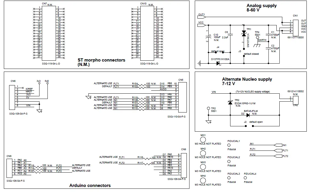
Figure 6. X-NUCLEO-OUT06A1 circuit schematic (2 of 2)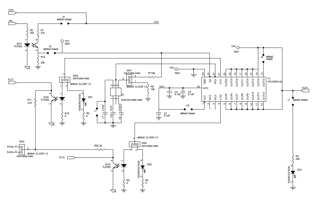
Bill of materials
Table 4. X-NUCLEO-OUT06A1 bill of materials
| Item | Q.ty | Ref. | Part/value | Description | Manufacturer | Order code |
| 1 | 0 | C1 C2 | 4700 pF 1825 (4564 metric) 3000 V (3kV) ±10% X7R | Ceramic capacitors (not mounted) | Vishay Vitramon | HV1825Y472KXHATHV |
| 2 | 3 | C3 C4 C5 | 0.1 µF 0805 (2012 metric) 100 V ±10% X7R | Ceramic capacitors | Würth Elektronik | 885012207128 |
| 3 | 1 | C6 | 2.2 µF 1206 (3216 metric) 100 V ±10% X7R | Ceramic capacitor | AVX Corporation | 12061C225KAT2A |
| 4 | 1 | C7 | 470 pF 0603 (1608 metric) 50 V ±5% C0G/NP0 | Ceramic capacitor | Würth Elektronik | 885012006061 |
| 5 | 1 | C8 | 47 nF 0603 (1608 metric) 50 V ±10% X7R | Ceramic capacitor | Murata Electronics North America | GCM188R71H473KA55D |
| 6 | 1 | C9 | 470 nF 0603 (1608 metric) 25 V ±10% X7R | Ceramic capacitor | Würth Elektronik | 885012206075 |
| 7 | 0 | C10 | 100 µF radial, can 100 V ±20% | Ceramic capacitor (not mounted) | Würth Elektronik | 860130878011 |
| 8 | 1 | CN1 | 5 positions, side entry, 5 mm | Terminal block | Würth Elektronik | 691137710005 |
| 9 | 0 | CN2 | 2 positions, 7.4X7 pitch 3.5 mm, side entry | Terminal block (not mounted) | Würth Elektronik | 691214110002 |
| 10 | 1 | CN5 | TH 2.54 mm | 10 ways, 1 row | Samtec Inc. 4UCONN | ESQ-110-14-T-S 17896 |
| 11 | 2 | CN6 CN9 | TH 2.54 mm | 8 ways, 1 row | Samtec Inc. 4UCONN | ESQ-108-14-T-S 15782 |
| 12 | 0 | CN7 CN10 | 38 positions, 0.1 mm, gold PCB | Connector receptacles (not mounted) | Any | Any |
| 13 | 1 | CN8 | TH 2.54 mm | 6 ways, 1 row | Samtec Inc. 4UCONN | ESQ-106-04-T-S 15781 |
| 14 | 1 | D1 | STPS1H100A, SMA | 100 V, 1 A power Schottky rectifier | ST | STPS1H100A |
|
15 |
0 |
D2 |
BAT48JFILM, SOD323 | 40 V, 350 mA axial general purpose signal Schottky diode (not mounted) |
ST |
|
| 16 | 1 | DG1 | 0603 (1608 metric) 20 mA SMD | Green LED | Würth Elektronik | 150060GS75000 |
| 17 | 2 | DR1 DR2 | 0603 (1608 metric) 20 mA SMD | Red LEDs | Würth Elektronik | 150060RS75000 |
| 18 | 3 | ISO1 ISO2 ISO3 | LSOP04, 5 kV | Optoisolators | Würth Elektronik | 140109146000 |
| 19 | 8 | J1 J2 J3 J4 J5 J6 J8 J10 | JUMPER-con2-strip-male TH 2.54 mm | Jumpers | Würth Elektronik | 61300211121 |
| 20 | 0 | J7 | JUMPER-con2-strip-male | Jumper (not mounted) | ||
| 21 | 1 | J9 | con6-2×3-strip-male | Connector header | Würth Elektronik | 61300621121 |
| 22 | 1 | R1 | 27 K 0603 (1608 metric) 0.1 W, 1/10 W ±1% SMD | Resistor | Yageo | RC0603FR-0727KL |
| Item | Q.ty | Ref. | Part/value | Description | Manufacturer | Order code |
| 23 | 1 | R2 | 390 0603 (1608 metric) 0.1 W, 1/10 W ±1% SMD | Resistor | Yageo | RC0603FR-07390RL |
| 24 | 2 | R3 R12 | 22 k 0603 (1608 metric) 0.1 W, 1/10 W ±1% SMD | Resistors | Yageo | RC0603FR-0722KL |
| 25 | 4 | R4 R5 R9 R10 | 0 0603 (1608 metric) 0.1 W, 1/10 W ±1% SMD | Resistors | Panasonic Electronic Components | ERJ-3GEY0R00V |
| 26 | 2 | R6 R11 | 2.2 K 0603 (1608 metric) 0.1 W, 1/10 W ±1% SMD | Resistors | Yageo | RC0603FR-072K2L |
| 27 | 1 | R7 | 100k 0603 (1608 metric) 0.1 W, 1/10 W ±1% SMD | Resistor | Yageo | RC0603FR-07100KL |
| 28 | 1 | R8 | 10 k 0603 (1608 metric) 0.1 W, 1/10 W ±1% SMD | Resistor | Yageo | RC0603FR-0710KL |
| 29 | 3 | R101 R103 R114 | 100 0603 (1608 metric) 0.1 W, 1/10 W ±1% SMD | Resistors | Yageo | RC0603FR-07100RP |
|
30 |
0 | R102 R104 R107 R115 R116 R117 R118 R119 R120 |
100 0603 (1608 metric) 0.1 W, 1/10 W ±1% SMD |
Resistors (not mounted) |
Yageo |
RC0603FR-07100RP |
| 31 | 4 | SW1 SW2 SW3 SW4 | con3-strip-male TH 2.54 mm | Connector headers | Würth Elektronik | 61300311121 |
| 32 | 5 | TP1 TP2 TP3 TP4 TP5 | 5001 0.100″ diameter 0.180″ L (2.54 mm x 4.57 mm) | Test points | Keystone Electronics | 5001 |
| 33 | 1 | TR1 | SM15T39CA, SMC C2 | 1500 W, 33.3 V TVS in SMC | ST | SM15T39CA |
| 34 | 0 | TR2 | ESDA15P60-1U1M, QFN-2L | High-power transient voltage suppressor (not mounted) | ST | |
| 35 | 1 | U1 | IPS1025H-32, PSSO24 | High-side switch with smart driving for capacitive loads | ST | |
| 36 | 13 | – | 2.54 mm | Jumpers | Würth Elektronik | 60900213421 |
References
Freely available on www.st.com:
- IPS1025H-32 datasheet
- UM2864: “Getting started with X-CUBE-OUT5 industrial digital output software for STM32 Nucleo”
- NUCLEO-F401RE datasheet
- NUCLEO-G431RB datasheet
Board versions
Table 5. X-NUCLEO-OUT6A1 versions
| Finished good | Schematic diagrams | Bill of materials |
| X$NUCLEO-OUT06A1 (1) | X$NUCLEO-OUT06A1 schematic diagrams | X$NUCLEO-OUT06A1 bill of materials
|
Regulatory compliance information
Formal Notice Required by the U.S. Federal Communications Commission
FCC NOTICE
This kit is designed to allow:
(1) Product developers to evaluate electronic components, circuitry, or software associated with the kit to determine
whether to incorporate such items in a finished product and
(2) Software developers to write software applications for use with the end product.
This kit is not a finished product and when assembled may not be resold or otherwise marketed unless all required FCC equipment authorizations are first obtained. Operation is subject to the condition that this product not cause harmful interference to licensed radio stations and that this product accept harmful interference. Unless the assembled kit is designed to operate under part 15, part 18 or part 95 of this chapter, the operator of the kit must operate under the authority of an FCC license holder or must secure an experimental authorization under part 5 of this chapter 3.1.2.
Formal Product Notice Required by Industry Canada Innovation, Science and Economic Development
Canada compliance:
For evaluation purposes only. This kit generates, uses, and can radiate radio frequency energy and has not been tested for compliance with the limits of computing devices pursuant to Industry Canada (IC) rules.
Revision history
Table 6. Document revision history
| Date | Revision | Changes |
| 24-Mar-2022 | 1 | Initial release. |
IMPORTANT NOTICE – READ CAREFULLY
STMicroelectronics NV and its subsidiaries (“ST”) reserve the right to make changes, corrections, enhancements, modifications, and improvements to ST products and/or to this document at any time without notice. Purchasers should obtain the latest relevant information on ST products before placing orders. ST products are sold pursuant to ST’s terms and conditions of sale in place at the time of order acknowledgment.
Purchasers are solely responsible for the choice, selection, and use of ST products and ST assumes no liability for application assistance or the design of purchasers’ products.
No license, express or implied, to any intellectual property right is granted by ST herein.
Resale of ST products with provisions different from the information set forth herein shall void any warranty granted by ST for such product.
ST and the ST logo are trademarks of ST. For additional information about ST trademarks, refer to www.st.com/trademarks. All other product or service names are the property of their respective owners.
Information in this document supersedes and replaces information previously supplied in any prior versions of this document.
© 2022 STMicroelectronics – All rights reserved
References
 STMicroelectronics: Our technology starts with you
-
IPS1025H-32 - High efficiency, high-side switch with extended diagnostics and smart driving for capacitive loads - STMicroelectronics
-
X-NUCLEO-OUT06A1 - Industrial digital output expansion board based on IPS1025H-32 for STM32 Nucleo - STMicroelectronics
-
STMicroelectronics Trademark List - STMicroelectronics
-
Home - STMicroelectronics
-
STMicroelectronics: Our technology starts with you
-
BAT48 - 40 V, 350 mA Axial General purpose Signal Schottky Diode - STMicroelectronics
-
ESDA15P60-1U1M - High-power transient voltage supressor (TVS) - STMicroelectronics
-
IPS1025H-32 - High efficiency, high-side switch with extended diagnostics and smart driving for capacitive loads - STMicroelectronics
-
NUCLEO-F401RE - STM32 Nucleo-64 development board with STM32F401RE MCU, supports Arduino and ST morpho connectivity - STMicroelectronics
-
NUCLEO-G431RB - STM32 Nucleo-64 development board with STM32G431RB MCU, supports Arduino and ST morpho connectivity - STMicroelectronics
-
SM15T39CA - 1500 W, 33.3 V TVS in SMC - STMicroelectronics
-
STPS1H100 - 100 V, 1 A Power Schottky Rectifier - STMicroelectronics
-
STSW-LINK004 - STM32 ST-LINK utility (replaced by STM32CubeProgrammer) - STMicroelectronics
-
X-CUBE-OUT5 - Industrial digital output STM32Cube software expansion for X-NUCLEO-OUT05A1 and X-NUCLEO-OUT06A1 - STMicroelectronics
-
STM32CubeProg - STM32CubeProgrammer software for all STM32 - STMicroelectronics
-
STM32 Nucleo Boards - STMicroelectronics


