![]() Getting started with the X-NUCLEO-LED12A1 LED driver expansion board based
Getting started with the X-NUCLEO-LED12A1 LED driver expansion board based
on LED1202 for STM32 Nucleo
UM2879
User manual
Introduction
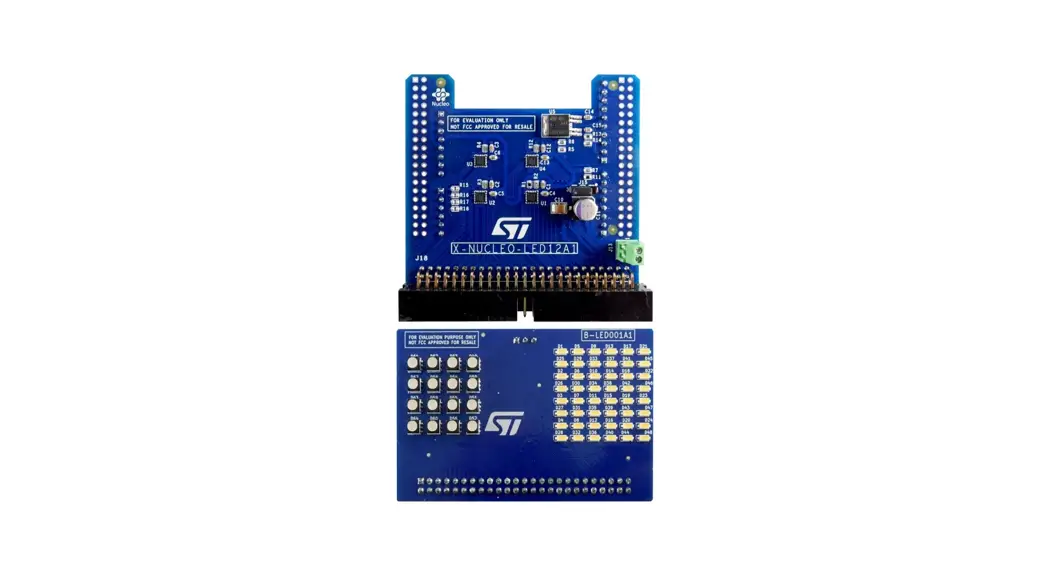
The X-NUCLEO-LED12A1 LED driver expansion board for STM32 Nucleo features four LED1202 devices that can drive up to 48 LEDs.
The LED1202 is a 12-channel low quiescent current LED driver, which guarantees 5 V output driving capability. Each channel is able to provide up to 20 mA with a headroom voltage of 350 mV (Typ.) only.
The output current can be adjusted separately for each channel through an 8-bit analog and 12-bit digital dimming control.
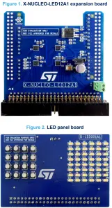
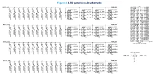
The X-NUCLEO-LED12A1 expansion board comes with an additional LED panel board that houses two LEDs matrices: a 6×8 white LED matrix and a 4×4 RGB matrix.
LED matrices can be supplied via an external power supply connected to the J13 connector and by selecting the right path through J15 jumper to reach the maximum luminosity available.
Getting started
Overview
The X-NUCLEO-LED12A1 expansion board features:
- Four LED1202 devices driving up to 48 LEDs
- One double row pin array connector for external LED panel connection
- One jumper selector for internal/external LED power supply
- One panel with 48 white LEDs/16 RGB LEDs included
- Arduino UNO R3 connectors
- Free comprehensive development firmware library compatible with STM32Cube
- Scalable solution for multiple board stack
- RoHS and WEEE compliant
Hardware requirements
The X-NUCLEO-LED12A1 expansion board is designed to be used with any STM32 Nucleo development board, although complete testing has been performed using the NUCLEO-L073RZ hosting the STM32L073RZ microcontroller.
System requirements
To use STM32 Nucleo development boards with the X-NUCLEO-LED12A1 expansion board, the following software and hardware are required:
- an STM32 Nucleo-64 development board
- a Windows® PC to install the firmware package
- a USB type A to Mini-B USB cable to connect the STM32 Nucleo board to the PC
- 128 MB of RAM and 40 MB of free hard disk space to install the firmware package (order code: X-CUBELED12A1)
Connectors
The X-NUCLEO-LED12A1 expansion board allows the user to test the functionality of the LED1202, together with the use of the additional LED panel board.
The 4 LED1202 ICs and the STM32 Nucleo development board are connected through CN5, CN6, CN8 and CN9 connectors (see the tables below).
Table 1. Interconnections between X-NUCLEO-LED12A1 expansion board and NUCLEO-L073RZ development board (left side)
| Signal | Connector | Pin number | NUCLEO-L073RZ | X-NUCLEO-LED12A1 |
| NC | CN6 Power | 1 | – | – |
| IOREF | 2 | – | (NC) | |
| RESET | 3 | – | – | |
| 3V3 | 4 | – | 3V3 | |
| 5V | 5 | – | 5V (VDD) | |
| GND | 6 | – | GND | |
| GND | 7 | – | GND | |
| VIN | 8 | – | – | |
| A0 | CN8 Power | 1 | PA0 | IRQ_MCU (alt.) |
| A1 | 2 | PA1 | IRQ_MCU (alt.) | |
| A2 | 3 | PA4 | IRQ_MCU (alt.) | |
| A3 | 4 | PB0 | IRQ_MCU (alt.) | |
| A4 | 5 | PC1 | NC | |
| A5 | 6 | PC0 | NC |
Table 2. Interconnections between X-NUCLEO-LED12A1 expansion board and NUCLEO-L073RZ development board (right side)
| Signal | Connector | Pin number | NUCLEO-L073RZ | X-NUCLEO-LED12A1 |
| D15 | CN5 Digital | 10 | PB8 | SCL_MCU |
| D14 | 9 | PB9 | SDA_MCU | |
| AVDD | 8 | AVID | NC | |
| GND | 7 | GND | NC | |
| D13 | 6 | PA5 | NC | |
| D12 | 5 | PA6 | NC | |
| D11 | 4 | PA7 | NC | |
| D10 | 3 | PB6 | NC | |
| D9 | 2 | PC7 | NC | |
| D8 | 1 | PA9 | NC | |
| D7 | CN9 Digital | 8 | PA8 | NC |
| D6 | 7 | PB10 | NC | |
| D5 | 6 | PB4 | NC | |
| D4 | 5 | PB5 | NC |
| Signal | Connector | Pin number | NUCLEO-L073RZ | X-NUCLEO-LED12A1 |
| D3 | CN9 Digital | 4 | PB3 | IRQ_MCU |
| D2 | 3 | PA10 | NC | |
| D1 | 2 | PA2 | NC | |
| D0 | 1 | PA3 | NC |
Host interface and GPIO connection
The X-NUCLEO-LED12A1 expansion board embeds four LED1202 devices and is powered by the STM32 Nucleo development board.
The devices are driven by the microcontroller via the I²C interface, connected through the same I²C bus, and synchronized by a clock chain.
Components
Figure 3. X-NUCLEO-LED12A1 expansion board component placement
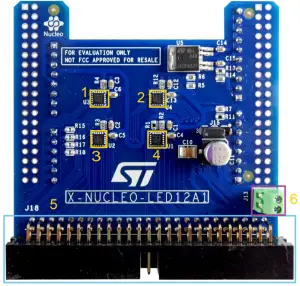
- LED1202
- LED1202
- LED1202
- LED1202
- LED panel connector
- LED panel power supply connector
LED1202
The LED1202 is a 12-channel low quiescent current LED driver which guarantees 5 V output driving capability. Each channel is able to provide up to 20 mA with a headroom voltage of 350 mV (Typ.) only. The output current can be adjusted separately for each channel by an 8-bit analog and 12-bit digital dimming control.
A slow turn-on and turn-off time improve the system’s low noise generation performance; moreover, the phase-shifting function helps to reduce the inrush current. Eight patterns can be stored in the internal registers for automatic sequencing without involving the MCU.
The pattern sequence can be also configured for duration time and number of repetitions. In multi-device applications, a common clock domain can be shared for timing synchronization.
The device features thermal shutdown and open LED detection. The device I²C interface is based on fast mode specification and works up to 400 kHz. Eight I²C addresses are possible by using two configuration pins (A0/A1) only.
Board setup
To test the expansion board follow the procedure below.
Step 1.
Connect the X-NUCLEO-LED12A1 expansion board to the STM32 Nucleo development board from the top through the Arduino UNO R3 connectors.
Step 2.
Power the STM32 Nucleo development board using a mini-B USB cable.
Step 3.
Program the firmware on the STM32 Nucleo development board using the provided example.
Step 4.
Reset the MCU using the STM32 Nucleo reset button.
Step 5.
Configure J15 jumper for internal or external LED power supply.
–Connect pin 1 with pin 2 for external LED power supply.
–Connect pin 2 with pin 3 for the internal LED power supply.
For the internal LED power supply, the PC USB port drives the LED current.
Important:
For the external LED power supply, the current capability has to be provided through the J13 connector. Do not apply an external voltage greater than 6 V: as this is the absolute maximum rating of LED1202 LED channels, it is recommended to remain below 5.5 V.
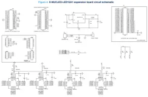
Schematic diagrams
Bill of materials
Table 3. X-NUCLEO-LED12A1 expansion board bill of materials
| Item | Q.ty | Ref. | Part/Value | Description | Manufacturer | Order code |
| 1 | 1 | CN5 Female on Top, Male on Bottom | CONN1x10 2.54 mm | Connector | Wurth | 6.13E+10 |
| 2 | 2 | CN6, CN9 Female on Top, Male on Bottom | CONN1x8 2.54 mm | Connectors | Wurth | 6.13E+10 |
| 3 | 2 | CN7, CN10 | CONN19x2 2.54, low insertion force | Connectors (not mounted) | Any | Any |
| 4 | 1 | CN8 Female on Top, Male on Bottom | CONN1x6 2.54 mm | Connector | Wurth | 6.13E+10 |
| 5 | 10 | C1, C2, C3, C4, C5, C6, C12, C13, C14, C15 | 1 µF, 16 V, C0603 | Capacitors | Any | Any |
| 6 | 1 | C10 | 22 µF, 16 V, CAPC-1210 | Capacitor | Any | Any |
| 7 | 1 | C11 | 180u 16V, CEVSMD_6V3X8_T | Capacitor | Any | Any |
| 8 | 1 | J13 | WR-TBL Series 2109 2.54 mm, horizontal entry, MORS_2P_2V54_P | Header | Wurth | 6.91E+11 |
| 9 | 1 | J15 | HEADERx3 2.54 mm | Header | Wurth | 6.13E+10 |
| 10 | 1 | J18 | CONN PLUG 25×2 2.54 mm, right angle | Header | Amphenol | T821150A1R100CEU |
| 11 | 2 | R1, R11 | 0 R, R0603 | Resistors | Any | Any |
| 12 | 8 | R2, R3, R4, R5, R6, R7, R12, R14 R13 | 10K, R0603 | Resistors | Any | Any |
| 13 | 1 | R13 | 36 K, R0603 | Resistor | Any | Any |
| 14 | 4 | R15, R16, R17, R18 | 0 R, R0603 | Resistors (not mounted) | Any | Any |
| 15 | 4 | U1, U2, U3, U4 | LED1202, VFQFPN20_3X3 | 12-channel low quiescent current LED driver | ST | LED1202QTR |
| 16 | 1 | U5 | LDL112PT-TR, PPAK | 1.2 A low quiescent current LDO with reverse current protection | ST | LDL112PT-TR |
Table 4. LED panel bill of materials
| Item | Q.ty | Ref. | Value | 1 | Part Number |
| 1 | 48 | D1, D2, D3, D4, D5, D6, D7, D8, D9, D10, D11, D12, D13, D14, D15, D16, D17, D18, D19, D20, D21, D22, D23, D24, D25, D26, D27, D28, D29, D30, D31, D32, D33, D34, D35, D36, D37, D38, D39, D40, D41, D42, D43, D44, D45, D46, D47, D48 | PLCC | Wurth | 1.58E+08 |
| 2 | 16 | D49, D50, D51, D52, D53, D54, D55, D56, D57, D58, D59, D60, D61, D62, D63, D64 | Wurth | 150353M153300 | |
| 3 | 1 | J1 | Multicomp | 2214S-50SG-85 | |
| 4 | 1 | JP1 | Wurth | 6.13E+10 |
Revision history
Table 5. Document revision history
| Date | Revision | Changes |
| 27-Sep-2021 | 1 | Initial release. |
| 8-Nov-21 | 2 | Updated Section 2 Connectors and Section 6 Board setup. |
IMPORTANT NOTICE – PLEASE READ CAREFULLY
STMicroelectronics NV and its subsidiaries (“ST”) reserve the right to make changes, corrections, enhancements, modifications, and improvements to ST products and/or to this document at any time without notice. Purchasers should obtain the latest relevant information on ST products before placing orders. ST
products are sold pursuant to ST’s terms and conditions of sale in place at the time of order acknowledgment. Purchasers are solely responsible for the choice, selection, and use of ST products and ST assumes no liability for application assistance or the design of Purchasers’ products.
No license, express or implied, to any intellectual property right is granted by ST herein.
Resale of ST products with provisions different from the information set forth herein shall void any warranty granted by ST for such product. ST and the ST logo are trademarks of ST. For additional information about ST trademarks, please refer to www.st.com/trademarks. All other product or service names are the property of their respective owners. Information in this document supersedes and replaces information previously supplied in any prior versions of this document.
© 2021 STMicroelectronics – All rights reserved


