FRICO FCR-230 Room Controller Instructions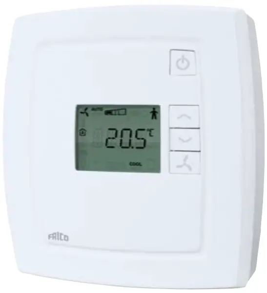
![]() Instruction for products with software version 1.2. Read this instruction before installation and wiring of the product. This product is BTL listed from software version 1.2-1-00 (BACnet stack 3.0.4).
Instruction for products with software version 1.2. Read this instruction before installation and wiring of the product. This product is BTL listed from software version 1.2-1-00 (BACnet stack 3.0.4).
![]() Consult documentation in all cases where this symbol is used, in order to find out the nature of the potential hazards and any actions to be taken.
Consult documentation in all cases where this symbol is used, in order to find out the nature of the potential hazards and any actions to be taken.
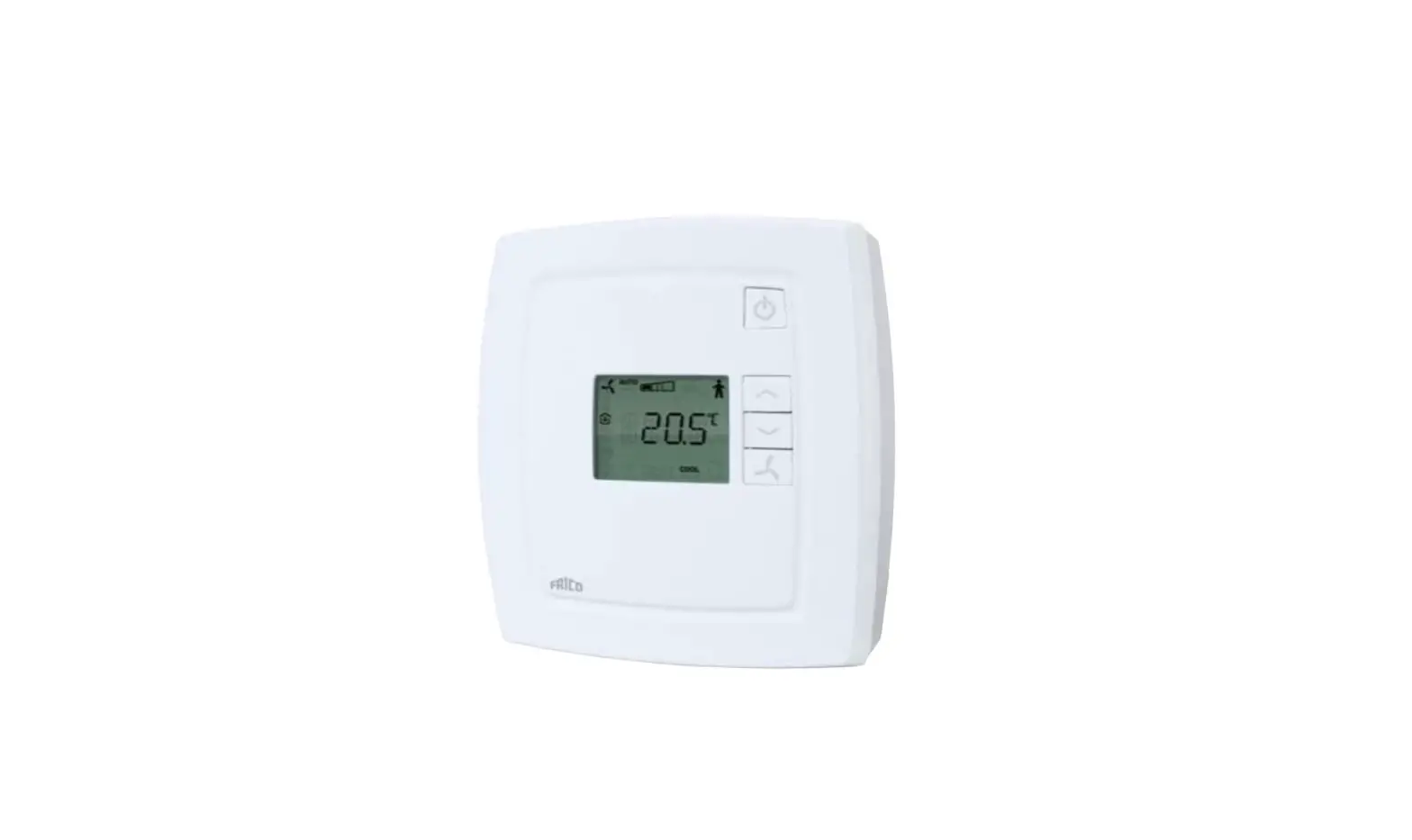
Room controller for controlling fan-coil units
FCR-230 is a room controller intended for controlling fan-coil heaters/ coolers and thermal actuators or 3-point actuators. Installation is directly on the wall or on an electrical connection box. The fan can be set to one of three speeds.
FCR-230 has change-over function and can be used for 2-pipe or 4-pipe systems.
For integration into a system, FCR-230 has communication via RS485 (Modbus, BACnet or EXOline). The device can be configured using the application Regio tool (version 1.3-1-05 or later), which can be downloaded from the Regin web site (www.regin.se).
Technical data
- Supply voltage: 230 V AC ±10 %, 50/60 Hz
- Power consumption: < 3 W
- Ambient temperature: 0…50°C
- Ambient humidity: Max 90 % RH
- Storage temperature: -20…+70°C
- Built-in temperature sensor: NTC type, range 0…50°C
- Inputs: Refer to connection illustrations and table below
- Outputs: Relays for fan control, 230 V AC, 3 A DO4, DO5 for actuators, Triac, 230 V AC, max. 300 mA
- Communication RS485: Modbus, EXOline (using automatic detection/switching) or BACnet
- Modbus: 8 bits, 1 or 2 stop bits. Odd, even (FI) or no parity
- Communication speed: 9600, 19200, 38400 bps (EXOline, Modbus and BACnet) or 76800 bps (BACnet only)
- Terminal blocks: Lift type for a maximum cable area 2.1 mm2
- Protection class: IP20
- Pollution degree: 2
- Overvoltage category: 3
- Material casing: Polycarbonate, PC
- Dimensions: 102 x 120 x 29 mm
Installation
Place the controller in a location that has a temperature representative for the room. A suitable location is approx. 1.6 m above floor level in a place with unobstructed air circulation.
Depress the locking tab in the upper edge of the controller with a screwdriver. Carefully turn the screwdriver until the bottom plate and the electronics unit are slightly separated (see figure 1). Then use the cutout that becomes visible in the edge of the bottom plate to open the upper edge completely (see figure 2). Do the same thing in the lower edge of the controller.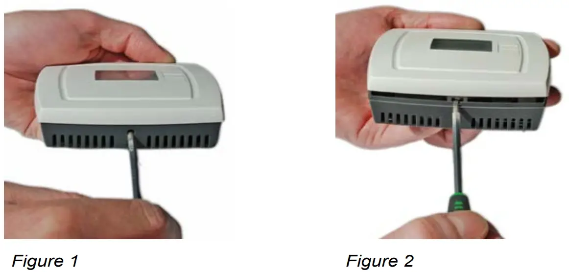
Lift the electronics unit up from the bottom plate. The bottom plate with terminals has a number of hole combinations. Select suitable holes and fasten the bottom plate on the wall or connection box, so that the arrows on the bottom plate point upwards. Do not tighten the screws too hard!
Note: FCR-230 does not indicate fan breakdown or overheating of the heating coil. Therefore, all connections must be made externally. An overheating protection or similar can be used to disconnect the supply voltage.
Disconnection
FCR-230 should be connected to a switch or circuit breaker in the building installation. This switch should be in close proximity to the controller and within easy reach of the operator, and should be marked as the disconnecting device for the equipment.
Always use the circuit breaker to disconnect the controller from the mains supply during maintenance of the fan-coil and actuators.
Settings
Control modes
FCR-230 can control heating and cooling in sequence or be set to seasonal switching between heating and cooling (change-over, see below).
Change-over function
FCR-230 has an input for change-over that automatically resets the output DO4 to operate with heating or cooling function. When the controller is used together with a 3-position actuator, output DO5 is also affected by the change-over function in accordance with the above. A sensor of type PT1000 can be connected to the input and be mounted so that it senses the temperature on the supply pipe to the coil. When the temperature exceeds 28°C, the output function is set to heating and when the temperature drops below 16°C, the output is set to cooling. As an alternative, a potential-free contact can be used.
The input function can be set to NO/NC.
To ensure satisfactory functioning when using a sensor, the system must have continuous primary circuit circulation. When the changeover function is not used, the input must be left disconnected.
When using an electric heater and the change-over function is set to heating, the sequence of operation for FCR-230 will be heating/heating and DO5 will be activated first.
If a change-over sensor is not connected, the sequence will be heating/heating. If cooling is to be used in the sequence, parameter 2 (change-over mode) must be changed manually.
Operating mode
There are four different operating modes. Switching between these modes is performed locally.
Comfort: ![]() is shown in the display. Heating and cooling have a smaller neutral zone NZC. An occupancy detector can be connected to the DI in order to select between Comfort and Economy. Switching between Comfort/Economy and Off can also be done via the On/Off button. Comfort/Economy is selected via the parameter list.
is shown in the display. Heating and cooling have a smaller neutral zone NZC. An occupancy detector can be connected to the DI in order to select between Comfort and Economy. Switching between Comfort/Economy and Off can also be done via the On/Off button. Comfort/Economy is selected via the parameter list.
Economy (Standby): “Standby” is shown in the display. The heating and cooling setpoints are freely adjustable. Factory settings: heating=15°C, cooling=30°C.
Off: The controller does not heat or cool and the fan stops (unless mould protection has been selected or the cool-down function for the electric heater is running, in which case the fan will still run).
Window: ![]() is shown in the display, the controller is off and the fan stops (unless mould protection has been selected or the cool-down function for the electric heater is running, in which case the fan will still run). The window contact is connected to the DI and must be configured.
is shown in the display, the controller is off and the fan stops (unless mould protection has been selected or the cool-down function for the electric heater is running, in which case the fan will still run). The window contact is connected to the DI and must be configured.
Occupancy detection
Parameter 3 determines if the DI is window contact input or occupancy detection input. An occupancy detector can be connected to the DI in order to switch between Comfort and Economy mode.
Setpoint
The setpoint is set using the INCREASE and DECREASE buttons. Parameter 24 determines what is shown in the display. Refer to the parameter list for details.
Setpoint limitation
In parameters 34 and 35, it is possible to set the maximum allowed setpoint increase and decrease respectively.
Example: If P35=5 and P34=3, the setpoint can be changed between 17°C and 25°C (see the picture below).
The basic setpoint can be changed in parameter 64 (factory setting=22°C).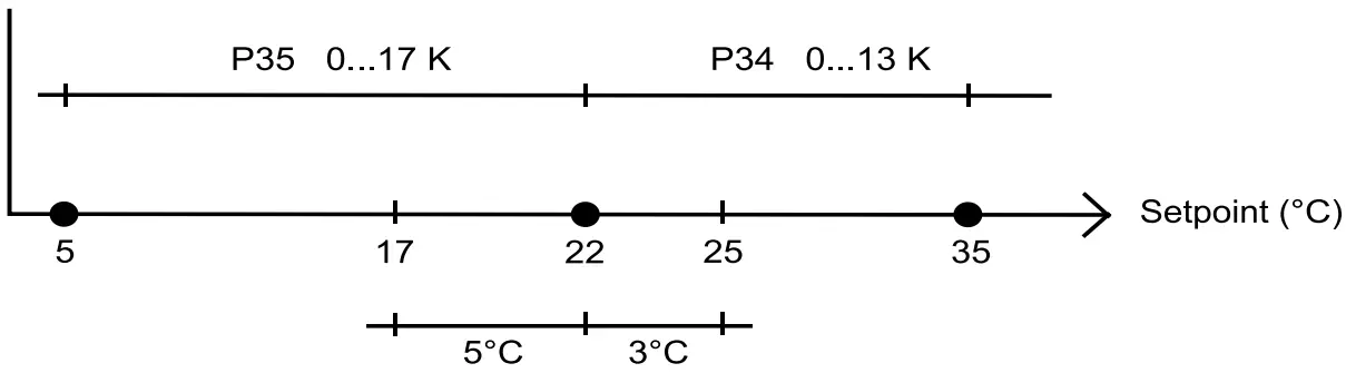
Figure 3: Example of setpoint limitation
Fan control
The fan can be controlled via FCR-230 with the following modes: Low speed, Medium speed, High speed, Auto. The current fan speed in the Auto mode depends on the heating or cooling demand and the settings for each speed.
When using automatic control, ”AUTO” is shown in the display. The number of fan speed steps can be selected via parameter 30.
If the parameter is set to 1, the first fan speed step will be used for fan control.
Via parameter 31, it is possible to set the fan to the lowest speed level when Auto mode is selected. If this parameter is set to 1, the fan will run in all operating modes except Off and Window (unless mould protection is active or the cool-down function for the electric heater is running, in which case the fan will run in these modes as well).
Manual control of the fan speed
By pressing the fan button, you change the fan speed according to the sequence I→II→III→AUTO. When using manual control, ”MAN” is shown in the display.
If the fan has been configured not to be affected by the heating or cooling demand, ”AUTO” will not be shown when pressing the fan button.
Indications
The display has the following indications:
- HEAT: Heating control
- COOL: Cooling control
 :The open window symbol is shown if this function has been configured and a window is open.
- OFF: The controller does not heat or cool
On/Off button
By pressing the On/Off button, FCR-230 will switch between Off mode and Comfort/Economy mode.
Parameter list
When the controller is in Comfort mode or Window mode, different parameter values can be set in a parameter list.
Hold the INCREASE and DECREASE buttons depressed simultaneously for about 5 seconds until the Service symbol is displayed and then press the INCREASE button twice.
First the display will show parameter 1. Use the INCREASE and DECREASE buttons to scroll between the parameters and press the On/Off button to select the desired parameter. The parameter number will then be replaced by the parameter value. The value can be changed using the INCREASE and DECREASE buttons. If a button is held depressed the value will start scrolling, first slowly and then with increasing speed. To exit the parameter list and go back to the basic display, press the INCREASE button until “EXIT” is shown (one step before parameter 1) and press the On/Off button. You can also exit the parameter list by pressing down the INCREASE and DECREASE buttons simultaneously.
The following parameters can be changed in the parameter list.
Nº = parameter number
FS = factory setting
NO = normally open
NC = normally closed
Nº | Description | FS |
| 1 | Control mode: 2=2-pipe system 3=4-pipe system 4=(Electric heater) N/A | 3 |
| 2 | Change-over mode: 0=Heating control, 1=Cooling control, 2=Automatic change-over depending on analogue temperature sensor or digital input | 0 |
| 3 | Operating mode when activating digital input 1, terminal 40/41: 0=Economy mode (occupancy detector) 1=Off mode (window contact) | 0 |
| 4 | Mould protection: 0=Not active 1=Active (fan never stops) | 0 |
| 5 | Neutral zone at Comfort mode (NZC). If the neu- tral zone is 2 K, the heating setpoint is equal to the setpoint minus 1 and the cooling setpoint is equal to the setpoint plus 1. | 0 K |
| 6 | Heating setpoint when unoccupied | 15°C |
| 7 | Cooling setpoint when unoccupied | 30°C |
| 8 | P-band for the room controller | 10 K |
| 9 | I-time for the room controller | 300 s |
| 10 | Not used for this model | |
| 11 | Switch off timer for Comfort mode | 0 min |
| 12 | Switch on delay for Comfort mode | 0 min |
| 13 | Sensor connected to AI1, terminal 42/43: 0=Internal sensor, 1=External room sensor | 0 |
| 14 | Sensor connected to UI1, terminal 43/44: 0=None, 1=Change-over digital, 2=Change-over analogue | 0 |
| 15 | Type of digital actuator: 0=Thermal, 1=3-point | 0 |
| 16- 17 | Not used for this model | |
| 18 | Period time for heating actuator with thermal actuator | 60 s |
| 19 | Period time for cooling actuator with thermal actuator | 60 s |
| 20 | Runtime for heating actuator with increase/decrease actuator | 120 s |
| 21 | Runtime for cooling actuator with increase/decrease actuator | 120 s |
| 22 | Time in hours between exercise of heating actuator | 23 |
| 23 | Time in hours between exercise of cooling actuator | 23 |
| 24 | Setpoint or actual value shown in the display: 0=Actual, setpoint when changing the setpoint, 1=Actual, setpoint adjustment when changing the setpoint, 2=Setpoint, 3=Only the setpoint adjustment | 0 |
| 25 | Configuration of fan control: 0=No control, 1=The fan is controlled by heating requirement, 2=The fan is controlled by cooling requirement, 3=The fan is controlled by heating and cooling requirement. When using an electric heater, this parameter should only be set to 1 or 3, or the heater may be overheated. | 3 |
| 26 | Start signal in % of the controller output, heating or cooling, for fan speed 1 | 20 (5 when using an electric heater) |
| 27 | Start signal in % of the controller output, heating or cooling, for fan speed 2 | 60 |
| 28 | Start signal in % of the controller output, heating or cooling, for fan speed 3 | 100 |
| 29 | Hysteresis for start/stop of fans in % of the controller output. (N/A) | 5 |
| 30 | Number of fan speeds (N/A) | 3 |
| 31 | Fan speed in the Auto mode: 0=The fan speed follows the cooling/heating output, 1=The fan speed is minimum limited to the lowest speed | 0 |
| 32 | Temperature compensation on AI1 | 0 K |
| 33 | Temperature compensation for the internal room sensor | 0 K |
| 34 | Highest permitted setpoint offset upwards. Set- table value=0…13 K. Starting point=22°C. | 13 K |
| 35 | Highest permitted setpoint offset downwards. Set- table value=0…17 K. Starting point=22°C. | 17 K |
| 36 | NO/NC digital input 1: 0=NO, 1=NC | 0 |
| 37 | NO/NC universal input 1: 0=NO, 1=NC | 0 |
| 38 | NO/NC digital output 4: 0=NO, 1=NC | 1 |
| 39 | NO/NC digital output 5: 0=NO, 1=NC | 1 |
| 40 | Manual/Auto heating output signal: 0=Off, 1=Manual, 2=Auto | 2 |
| 41 | Manual/Auto cooling output signal: 0=Off, 1=Manual, 2=Auto | 2 |
| 42 | Heating output signal in manual mode | 0 |
| 43 | Cooling output signal in manual mode | 0 |
| 44 | Model | – |
| 45 | Version Major | – |
| 46 | Version Minor | – |
| 47 | Released or beta version | – |
| 48 | Revision | – |
| 49 | Display backlight low | 0 |
| 50 | Display backlight high | 30 |
| 51 | EXOline PLA address | – |
| 52 | EXOline ELA address | – |
| 53 | Modbus address | 254 |
| 54 | Modbus communication parity bit: 0=No parity, 1=Odd parity, 2=Even parity | 2 |
| 55 | Modbus timeout for character (t1.5) in ms. Should be 1.5 times a character, i.e. at least 2 ms. | 2 ms |
| 56 | Modbus answer delay (t3.5) in ms. Should be 3.5 times a character, i.e. at least 5 ms. | 5 ms |
| 57 | Communication protocol: 0=EXOline/Modbus, 1=BACnet MS/TP | 0 |
| 58 | BACnet MS/TP MAC address 0-127=master address, 128-254=slave address | – |
| 59 | The 4 low numbers in the BACnet device ID, 0-9999 | – |
| 60 | The 3 high numbers in the BACnet device ID | – |
| 61 | BACnet MS/TP Max. master | 127 |
| 62 | Communication protocol speed: 0=9600 bps, 1=19200 bps, 2=38400 bps, 3=76800 bps (alternative 3 only applies to BAC- net) | 0 |
| 63 | Resets communication parameters (not address- es) to their factory settings: 1=Factory settings (EXOline/Modbus@9600) | 0 |
| 64 | Basic setpoint. Settable value=5…50°C. | 22°C |
Recommended settings for Frico convectors:
Nº | TKW heat | TKW cool | TKW change over |
| 2 | 0 (FS) | 1 | 2 |
14 | 0 (FS) | 0 (FS) | 2 |
| 31 | 0 (FS) | 0 (FS) | 0 (FS) |
Nº | SL/SLS R heat | SL/SLS R cool | SL/SLS R change over |
| 2 | 0 (FS) | 1 | 2 |
14 | 0 (FS) | 0 (FS) | 2 |
| 31 | 1 | 1 | 1 |
Wiring
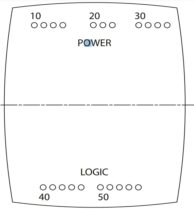
Figure 4: Bottom plate connections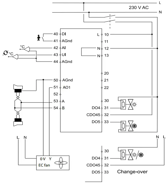
Figure 5: Connection diagram with water heater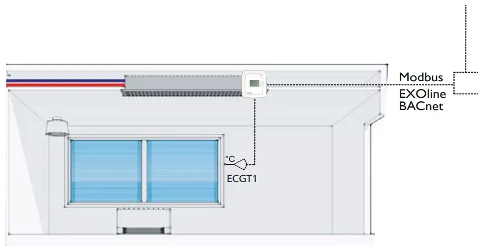
Figure 6: internal placement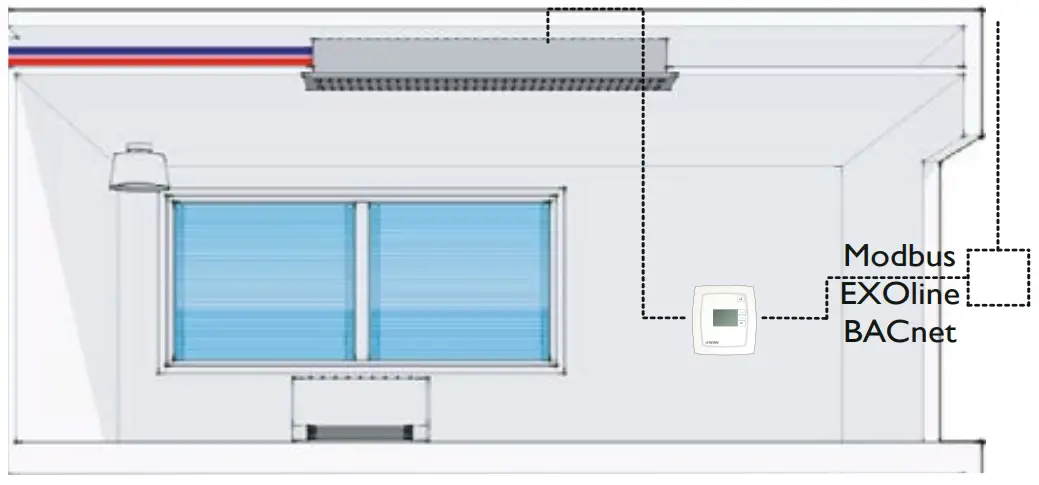
Figure 8: External placement
Connection of different actuators
When connecting thermal actuators, DO4 is used for heating actuators and DO5 for cooling actuators. If the installation is a 2-pipe installation and the change-over function is used, the actuator should be connected to DO4.
When connecting 3-point actuators, DO4 is used for increase signal and DO5 for decrease signal, even when the change-over function is used.
| 10 | L | 230 V AC Line | Power supply | ||
| 11 | – | Not connected | |||
| 12 | N | 230 V AC Neutral | Power supply (internally con- | ||
| nected to terminal 13) | |||||
| 13 | N | Fan-coil common / | Common fan-coil connec- | ||
| 230 V AC Neutral | tor (internally connected to | ||||
| terminal 12) | |||||
| 20 | DO1 | Fan-coil output 1 | Relay, 230 V AC*, 3 A | ||
| for fan control | |||||
| 21 | DO2 | Fan-coil output 2 | Relay, 230 V AC*, 3 A | ||
| for fan control | |||||
| 22 | DO3 | Fan-coil output 3 | Relay, 230 V AC*, 3 A | ||
| for fan control | |||||
| 30 | – | Not connected | |||
| 31 | DO4 | Digital output 4 for | Digital output. 230 V AC, max | ||
| heating/cooling | 300 mA. Max 2 A during 20 | ||||
| or opening with | ms. | ||||
| 3-point actuator | |||||
| 32 | CDO45 | Common DO4 & 5 | Common connection for | ||
| digital outputs 4 and 5 | |||||
| 33 | DO5 | Digital output 5 for | Digital output. 230 V AC, max | ||
| cooling or closing | 300 mA. Max 2 A during | ||||
| with 3-point actua- | 20 ms. | ||||
| tor. | |||||
| 40 | DI | Digital input | Potential-free window contact | ||
| or occupancy contact. Con- | |||||
| figurable for NO/NC. | |||||
| 41 | Agnd | Analogue ground | |||
| 42 | AI | Analogue input | External PT1000 instead of | ||
| the internal NTC | |||||
| 43 | UI | Universal input | Change-over input. Potential- | ||
| free switch (configurable for | |||||
| NO/NC) or PT1000. | |||||
| 44 | Agnd | Analogue ground | |||
| 50 | Agnd | Analogue ground | |||
| 51 | – | Analogue out A0I EC fan | |||
| 52 | – | Not connected | |||
| 53 | A | RS485 communication A | |||
| 54 | B | RS485 communication B | |||
*The sum of the current through DO1-DO3 is protected by a fuse
Low Voltage Directive (LVD) standards / EMC emissions & immunity standards
This product conforms to the EMC and LVD requirements in the European harmonised standards EN 60730-1:2000 and EN 60730-2- 9:2002 and carries the CE mark.
RoHS
This product conforms to the Directive 2011/65/EU of the European Parliament and of the Council.
Contact
Frico AB, Industrivägen 41, 433 61 Sävedalen, Sweden
Tel: +46 31 336 86 00,
Fax: +46 31 26 28 60
www.frico.net,
[email protected]
Our Address
Puravent, Adremit Limited, Unit 5a, Commercial Yard, Settle, North Yorkshire, BD24 9RH
Get In Touch![]() Call: 0845 6880112
Call: 0845 6880112![]() Email: [email protected]
Email: [email protected]