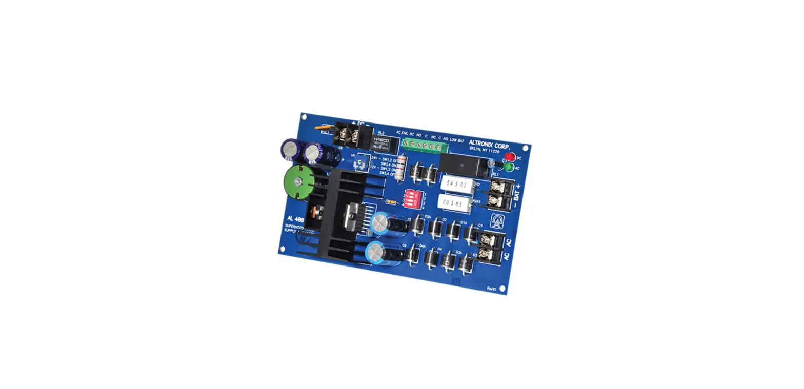
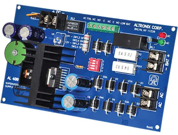
Altronix AL400ULB UL Recognized Power Supply Charger
Overview
Altronix AL400ULB power-limited supply/charger converts a 28VAC / 100VA input into a Class 2 Rated power-limited 12VDC or 24VDC output (see specifications).
Specifications
Agency Listings:
- UL Recognized component for:
UL 294* Access Control System Units.
UL 603 Power Supplies for Use with Burglar-Alarm Systems.
UL 1481 Fire Protective Signaling Systems.
Input:
- Input 28VAC / 175VA.
Output:
- Class 2 Rated power-limited output.
- 12VDC or 24VDC selectable output.
- 4A continuous supply current @ 12VDC.
- 3A continuous supply current @ 24VDC.
- Filtered and electronically regulated output.
Battery Backup:
- Built-in charger for sealed lead acid or gel type batteries.
- Maximum charge current 600mA.
- Automatic switch over to stand-by battery when AC fails. Visual Indicators:
- AC input and DC output LED indicators.
Supervision:
- AC fail supervision (form “C” contacts).
- Low battery supervision (form “C” contacts). Additional Features:
- Short circuit and thermal overload protection.
Board Dimensions (L x W x H approximate):
- 7.05” x 4.05” x 1.6” (179.1 mm x 102.9 mm x 40 mm).
*Access Control Performance Levels: Destructive Attack – N/A; Endurance – IV; Line Security – I; Stand-by Power – IV.
Specifications
Power Supply Output Specifications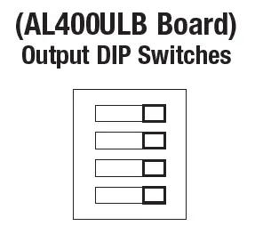
| Output VDC | Switch Position | Max. Stand-by Load DC | Max. Alarm Load DC | Stand-by Battery |
| 12VDC | SW 1, 2 ON, SW 3, 4 OFF | 4.0A 200mA | 4.0A 4.0A | 24V/40AH 12V/12AH |
| 24VDC | SW 1, 2 OFF, SW 3, 4 ON | 3.0A 200mA | 3.0A 3.0A | 24VDC 24V/12AH |
Stand-by Specifications
| Output | 4 hr. of Stand-by and 5 Minutes of Alarm | 24 hr. of Stand-by and 5 Minutes of Alarm | 60 hr. of Stand-by and 5 Minutes of Alarm |
| 12VDC / 40AH Battery | Stand-by = 4.0A Alarm = 4.0A | Stand-by = 1.0A Alarm = 4.0A | Stand-by = 300mA Alarm = 4.0A |
| 24VDC / 12AH Battery | – | Stand-by = 200mA Alarm = 3.0A | – |
| 24VDC / 40AH Battery | Stand-by = 3.0A Alarm = 3.0A | Stand-by = 1.0A Alarm = 3.0A | Stand-by = 300mA Alarm = 3.0A |
Installation Instructions
The AL400ULB should be installed in accordance with article 760 of The National Electrical Code or NFPA 72 as well as all applicable Local Codes.
- Mount AL400ULB in the desired location/enclosure (mounting hadware included).
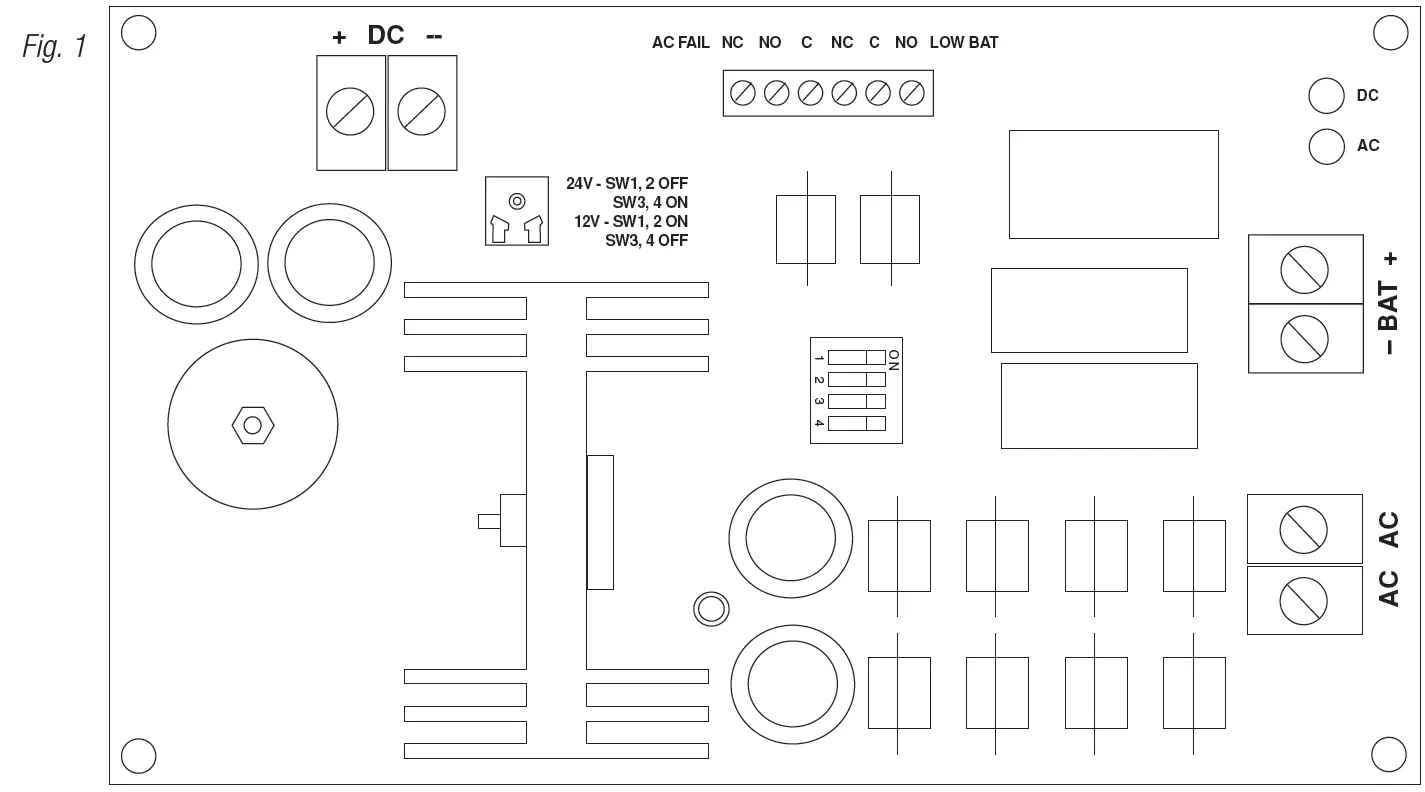
- Connect 28VAC / 175VA transformer to the terminals marked [AC AC], (Fig. 1).
Use 18 AWG or larger for all power connections (Battery, DC output).
Use 22 AWG to 18 AWG for the power-limited circuits (AC Fail/Low Battery reporting).
Keep power-limited wiring separate from non power-limited wiring (115VAC / 60Hz Input, Battery Wires). Minimum 0.25” spacing must be provided.
CAUTION: Do not touch exposed metal parts. Shut branch circuit power before installing or servicing equipment. There are no user serviceable parts inside. Refer installation and servicing to qualified service personnel. - Set the AL400ULB to the desired DC output voltage by setting the switches to the appropriate positions
(Power Supply Output Specifications Table). - Connect devices to be powered to the terminals marked [+ DC –] (Fig. 1).
- Measure output voltage before connecting devices. This helps avoiding potential damage.
- For Access Control applications batteries are optional. When batteries are not used, a loss of AC will result in the loss of output voltage. When the use of stand-by batteries is desired, they must be lead acid or gel type.
Connect battery to the terminals [– BAT +] (Fig. 1) as marked on the unit (battery leads included).
Use two (2) 12VDC batteries connected in series for 24VDC operation. - Connect supervisory trouble reporting devices to the outputs marked [LOW BAT, AC FAIL] supervisory relays marked
[NC, NO, C ] (Fig. 1). Use 22 AWG to 18 AWG for AC Fail and Low Battery reporting.
Maintenance
Unit should be tested at least once a year for the proper operation as follows:
Output Voltage Test: Under normal load conditions the DC output voltage should be checked for proper voltage level
(Power Supply Output Specifications Table).
Battery Test: Under normal load conditions check that the battery is fully charged, check specified voltage both at the battery terminal and at the board terminals marked [– BAT +] to ensure that there is no break in the battery connection wires.
Note: Maximum charging current under discharges is 1.25A.
Note: Expected battery life is 5 years; however, it is recommended changing batteries in 4 years or less if needed.
LED Diagnostics
| LED | ON | OFF |
| AC (Green) | Normal operation | No AC input |
| DC (Red) | Normal operation | No DC output |
Terminal Identification
| Terminal Legend | Function/Description |
| AC, AC | Low voltage (28VAC) transformer connections. |
| + DC – | 12VDC @ 4A or 24VDC @ 3A continuous power-limited output. |
| AC Fail NC, NO, C | Indicates loss of AC power, e.g. connect to audible device or alarm panel. Relay normally energized when AC power is present. Contact rating 1A @ 30VDC. |
| Bat Fail NC, C, NO | Indicates low battery condition, e.g. connect to alarm panel. Relay normally energized when DC power is present. Contact rating 1A @ 30VDC. |
| – BAT + | Stand-by battery connections. Maximum charge current 600mA. |
Altronix is not responsible for any typographical errors. 140 58th Street, Brooklyn, New York 11220 USA | phone: 718-567-8181 | fax: 718-567-9056
website: www.altronix.com | e-mail: [email protected] | Lifetime Warranty IIAL400ULB – Rev. 030619


