SWHT611 Water Tank and Mounting Frame
WOODBRIDGE Water Tank and Mounting Frames WHT611 Installation Manual
List of Main Installation Accessories
| No. | Description | Qty |
|---|---|---|
| 1 | Expansion screw | 4 |
| 2 | Three-valve | 1 |
| 3 | Angle valve | 1 |
| 4 | Socket head screw | 2 |
| 5 | Cistern cover | 1 |
| 6 | Plastic holder | 1 |
| 7 | Plastic holder cover | 1 |
| 8 | Connecting screw | 2 |
| 9 | Ceramic bowl fixing accessories | 2 |
| 10 | Straight tube | 1 |
| 11 | Connecting pipe | 1 |
| 12 | Big and small plugs | 2 |
| 13 | Draining syphon | 1 |
| 14 | Mounting bracket | 1 |
| 15 | Draining syphon holder | 1 |
| 16 | Braided tube | 1 |
| 17 | Power cord (12V) | 1 |
| 18 | Corrugated pipe | 2 |
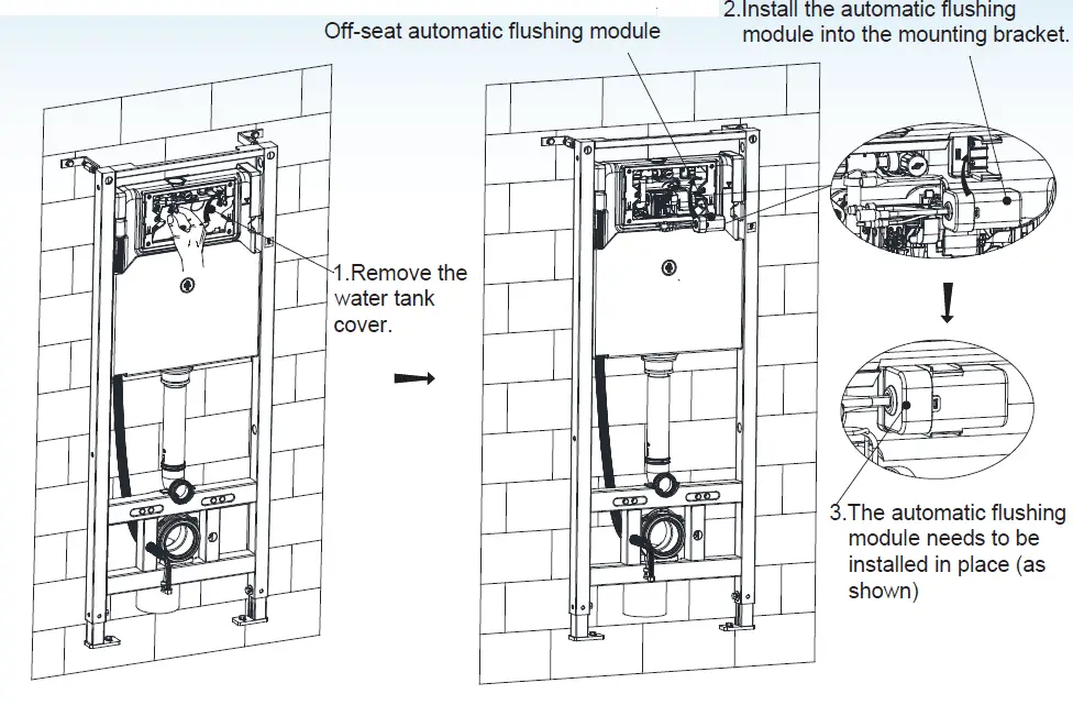
| 19 | Off-seat automatic flushing module | 1 |
Function
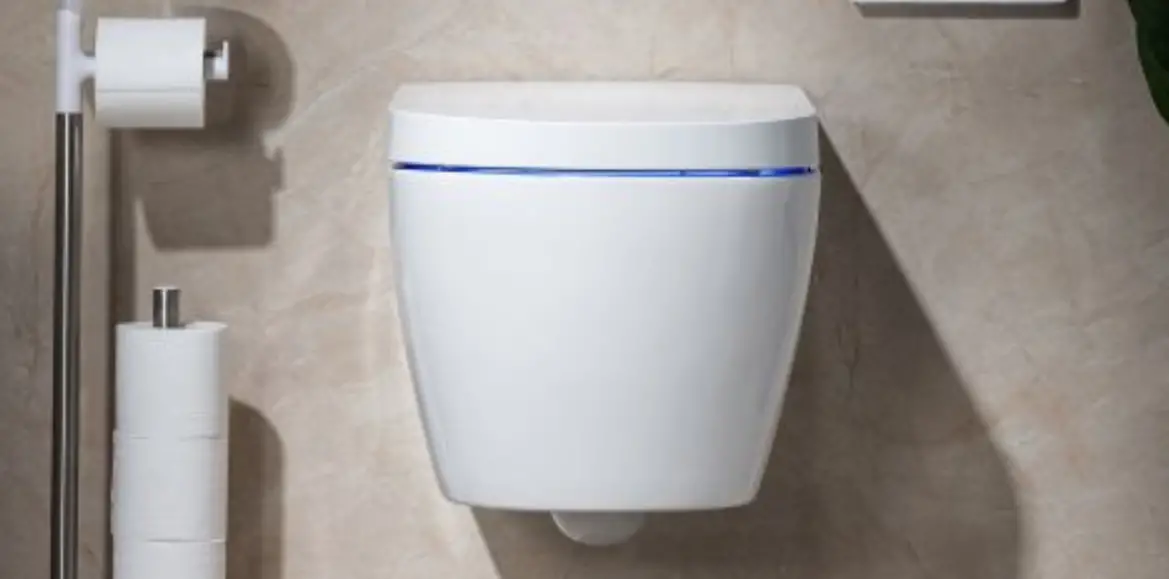
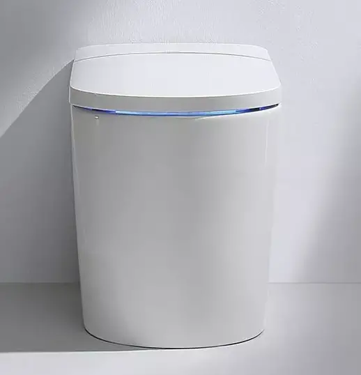
The Woodbridge Water Tank and Mounting Frames WHT611 is designed to mount the draining syphon and smart toilet water inlet pipe. The product is used to protect the water and electric circuits.
According to the signal provided by the smart toilet, it automatically identifies the full and half flush.
Important Instructions
Option 1 Mounting wall Mounting frame
NOTES:
- Mount before bricks building.
- All size unit in MM.
- Follow the material product, should there is an unconformity
with drawing. FFL 0 Finished Floor.
Drainage System Layout
Drawing 1 to 3 are three different installation systems for drain pipe. Customers should confirm whichever installation system according to the drainage outlet position. If the drainage outlet does not fall within the three systems, customer should follow one of three drainage system layouts to correspond installation of our concealed cistern.
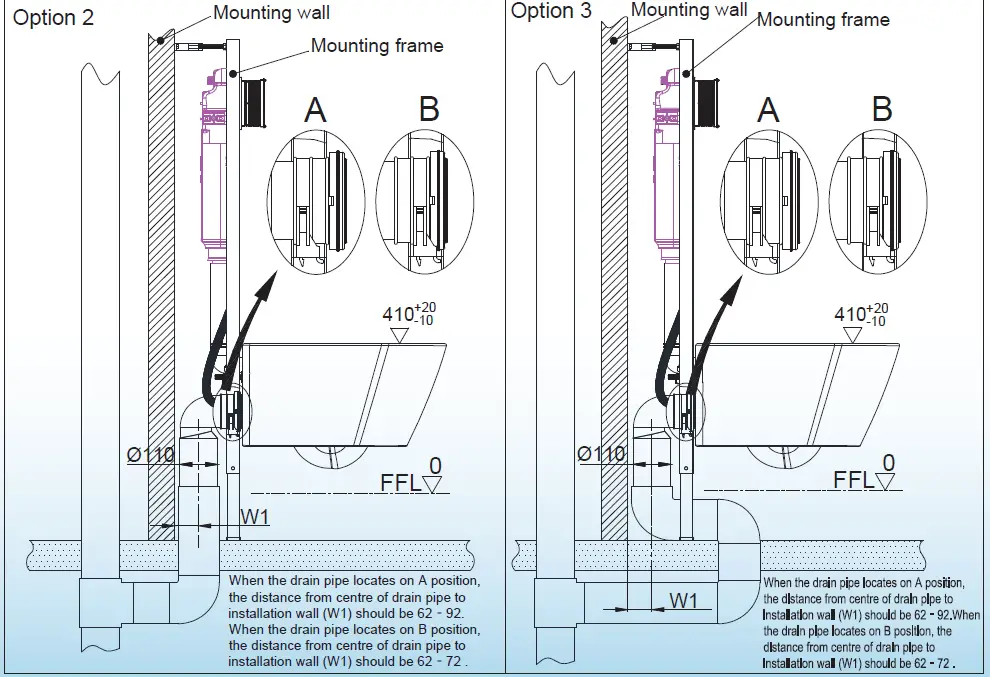
Option 2 Mounting wall
When the drain pipe locates on A position, the distance from center of drain pipe to installation wall (W1) should be 62-92.When the drain pipe locates on B position, the distance from center of drain pipe to installation wall (W1) should be 62-72.
Option 3 Mounting frame
When the drain pipe locates on A position, the distance from center of drain pipe to installation wall (W1) should be 62-92. When the drain pipe locates on B position, the distance from center of drain pipe to installation wall (W1) should be 62-72.
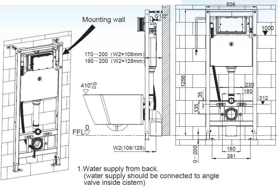
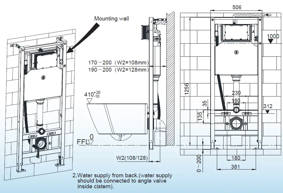
General Dimension and Water Supply Drawing
Water Supply from Back
(Water supply should be connected to angle valve inside cistern)
Mounting wall:
- G1/2
- 170j200cW2=108mm
- 190j200cW2=128mm
- 410+-1200
- 230
- 180
- 312
- 1256
- 135
- 35
- 0 FFL
- W2(108/128)
Water Supply from Back:
- G1/2
- 506
- 1000
- 170j200cW2=108mm
- 190j200cW2=128mm
- 410+-1200
- 230
- 180
- 312
- 1256
- 135
- 35
- 0 FFL
- W2(108/128)
- 0j200
- 180
- 381
Switch Between Rear Hole Water Inlet and Top Hole Water Inlet
If the water cannot enter the rear hole during actual installation, you can switch to the top hole according to the following steps:
- Remove the cistern cover.
- Remove the rubber plug from the top water inlet hole.
- Install the water supply hose to the top water inlet hole.
- Connect the other end of the water supply hose to the water supply pipe.
- Turn on the water supply and check for leaks.
- Replace the cistern cover.
Drill Holes on Mounting Wall and Floor and Install Expansion Screws
The tinsealral dimension is not provided in the user manual.
Please refer to the installation site or consult a professional for assistance.
Customer Service
For further assistance, please contact Woodbridge customer service at 562-229-0088 (Monday – Friday 9 AM – 5 PM Pacific Time) or email [email protected]. You can also visit their website at www.woodbridgebath.com.
20211112 REV. 1
Product Usage Instructions
- Before installation, confirm the drainage outlet position and select an appropriate drainage system layout.
- Mount the product before building bricks. Check the size unit in MM and follow the material product.
- For water supply from back installation, connect the water supply to angle valve inside cistern as indicated in the General Dimension and Water Supply Drawing section.
- If you need to switch between rear hole water inlet and top hole water inlet, follow the instructions provided in the Switch Between Rear Hole Water Inlet and Top Hole Water Inlet section.
- For drilling holes on mounting wall and floor and installing expansion screws, refer to the installation site or consult a professional for assistance.
- If you need further assistance, please contact Woodbridge customer service at 562-229-0088 (Monday – Friday 9 AM – 5 PM Pacific Time) or email [email protected].
WATER TANK AND MOUNTING FRAME: SWHT611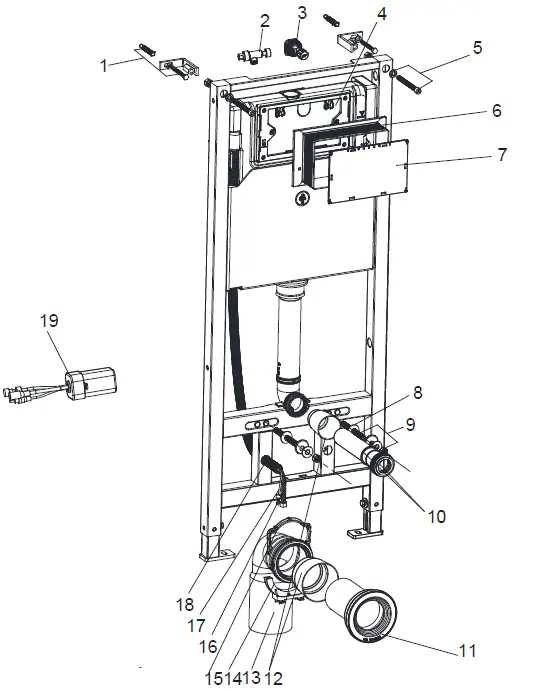
List of main installation accessories
| NO. | Description | Qty | Function |
| 1 | Expansion screw | 4 | Mounting of frame and wall bracket |
| 2 | Three -valve | 1 | To connect braided pipe |
| 3 | Angle valve | 1 | Fill valve inlet and shut-off |
| 4 | Socket head screw | 2 | Mounting of frame and locking into wall bracket |
| 5 | Cistern cover | 1 | Airproof tank and mounting of locking bracket |
| 6 | Plastic holder | 1 | To reserve space for installation of actuator at wall building |
| 7 | Plastic holder cover | 1 | To prevent dust and impurities into tank at wall building |
| 8 | Connecting screw | 2 | To mount ceramic bowl |
| 9 | Ceramic bowl fixing accessories | 2 | To mount ceramic bowl |
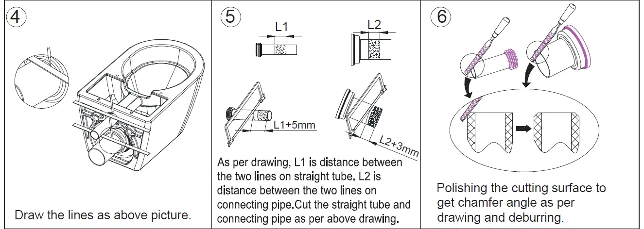
| 10 | Straight tube | 1 | To joint drain pipe into ceramic bowl (cutting in accordance with wall thickness) |
| 11 | Connecting pipe | 1 | |
| 12 | Big and small plugs | 2 | To reserve space for straight tube and connecting pipe |
| 13 | Draining syphon | 1 | To discharge liquid and solid waste from ceramic bowl |
| 14 | Mounting bracket | 1 | To mount draining syphon |
| 15 | Draining syphon holder | 1 | |
| 16 | Braided tube | 1 | Smart toilet water inlet pipe |
| 17 | Power cord (12V) | 1 | |
| 18 | Corrugated pipe | 2 | Used for protecting the water and electric circu its |
| 19 | Off-seat automatic flushing module | 1 | According to the signal provided by the smart toilet, automatically identify the full and half flush |
Important instruction:
- Please adhere to the following installation instructions. We shall not be responsible for failures and loss that are contributed to improper installation.
- Please confirm the fixation location of cistern prior to installation and obtain the finished floor surface. Draw FFL on installation wall and follow it as baseline from ZERO (0) level.
- The instructions have been composed based in the latest product specifications. We reserve the right to make modifications to the packaging and specifications without providing prior notification.
NOTES:
- Mount before bricks building.
- All size unit in MM.
- Follow the material product, should there is an unconformity with drawing.
FFL 0 Finished Floor.
Drainage System Layout.
Drawing 1 to 3 are three different installation systems for drain pipe. Customer should confirm whichever installation system according to drainage outlet position. If drainage outlet does not fall within the three systems, customer should follow one of three drainage system layout to correspond installation of our concealed cistern.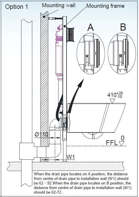
General dimension and water supply drawing
Switch between rear hole water inlet and top hole water inlet
☆ Tips: If the water cannot enter the rear hole during actual installation, you can switch to the top hole according to the following steps.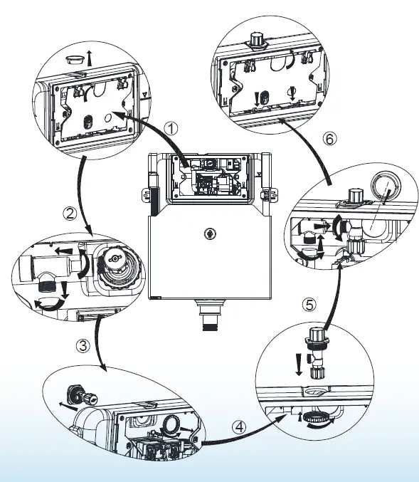
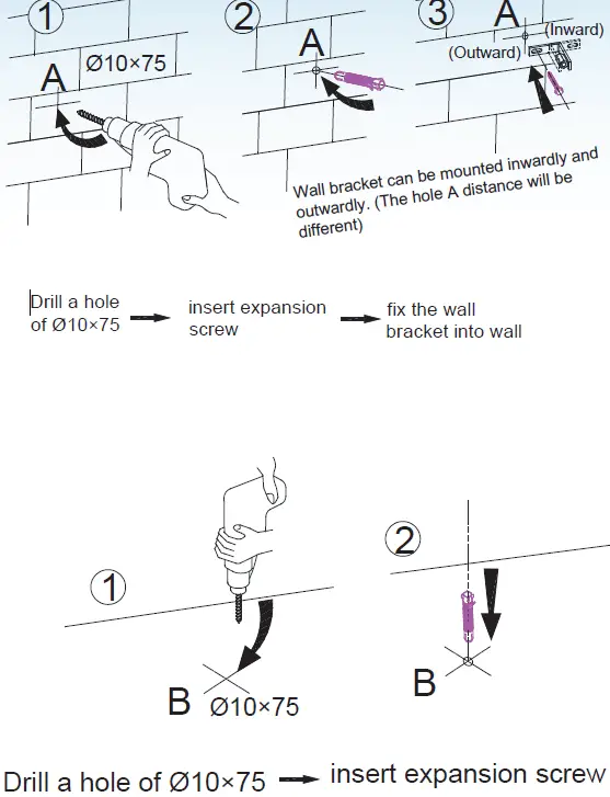
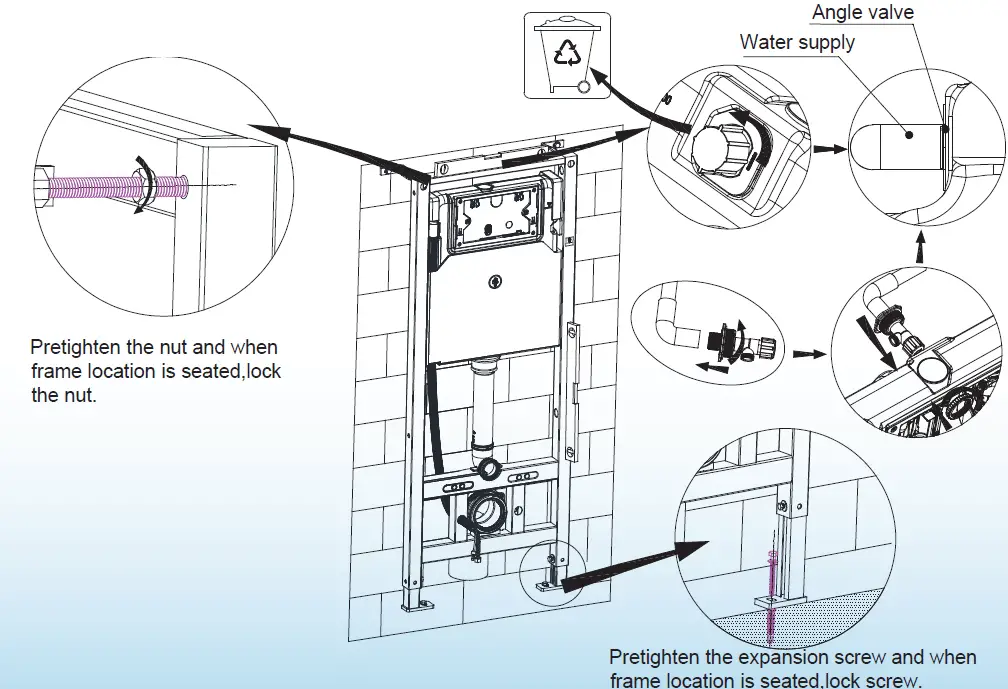
Drill holes on mounting wall and floor and install expansion screws
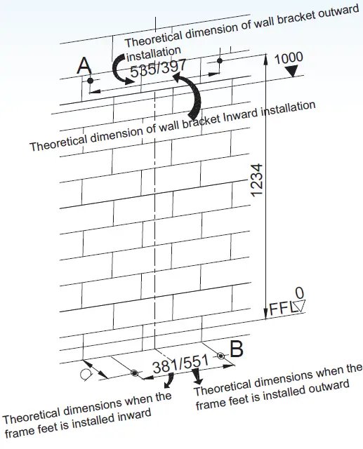 A dimension according to practical location of flushing pipe.
- Note: Above drilling are theoretical dimensions of frame mounting. Please follow by the practical location of frame.
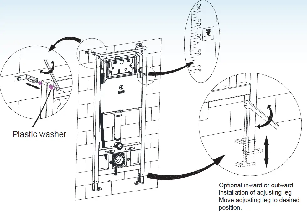
Adjustment of socket head screw and floor fixing accessories.
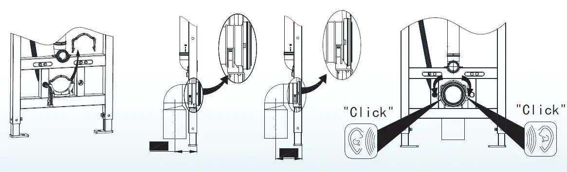
Adjustment and fixation of mounting frame
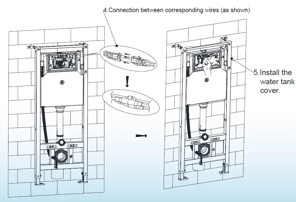
Installation of off-seat automatic flushing module
Mounting of installation accessories
Mounting of installation box, big and small plugs
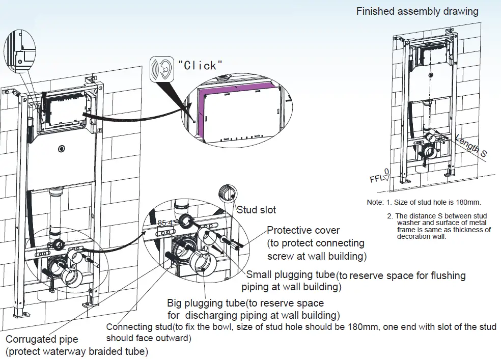
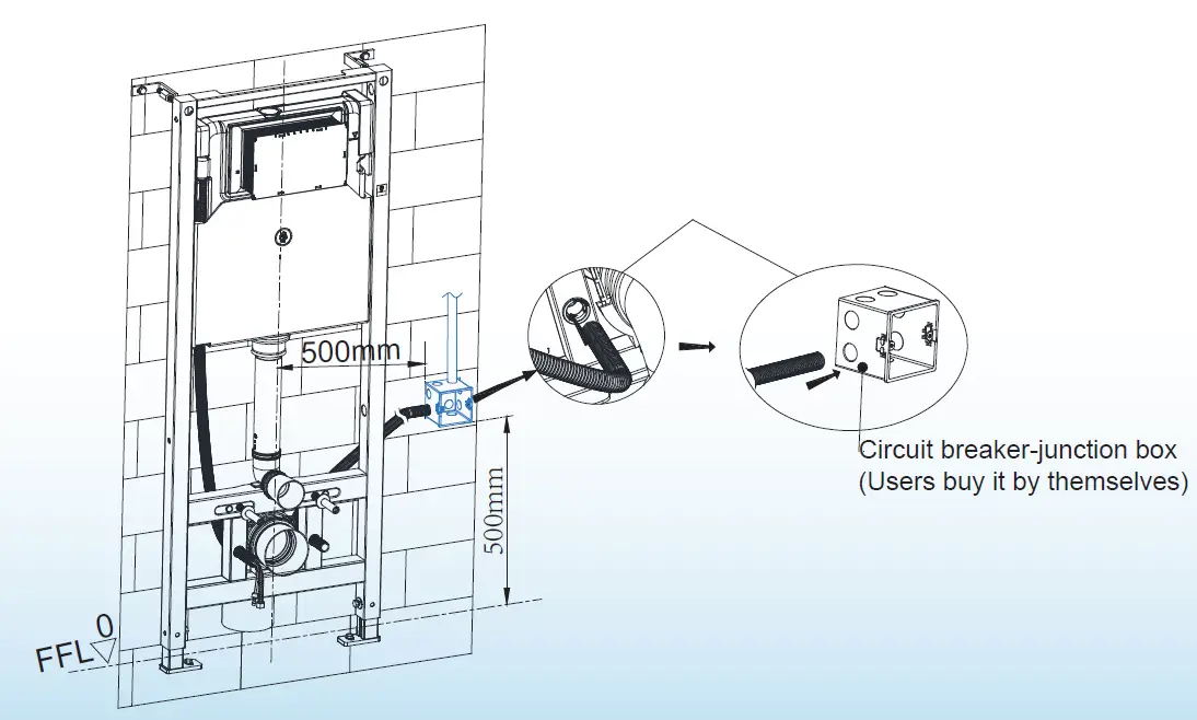
Installation steps of corrugated pipe (protect circuit connection line)
Installation steps of corrugated pipe (protect circuit connection line)
- Penetrate one end of the corrugated pipe into the back of the iron frame with a round hole of pipe clamp.
- Insert the other end into the circuit breaker-junction box (Users buy it by themselves)
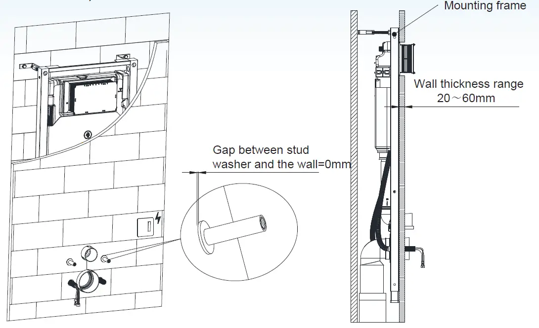
Wall thickness range 20-60mm (from frame outside surface to finished wall)
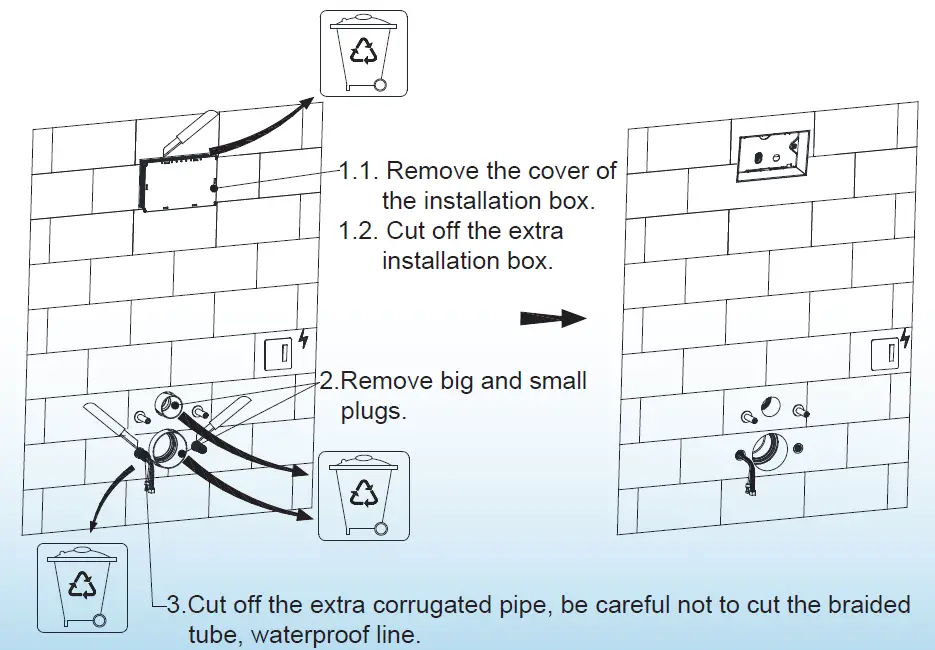
Remove extra installation boxes, corrugated pipe, big and small plugs
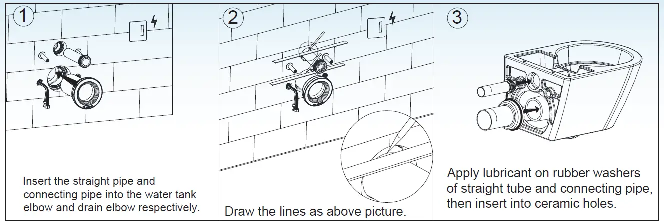
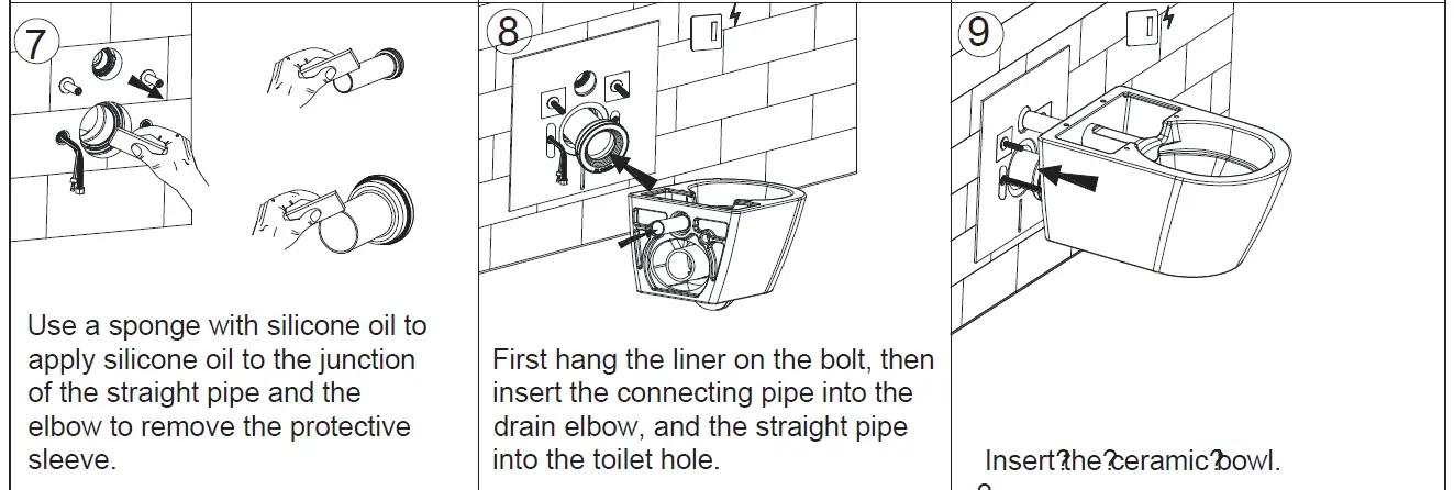
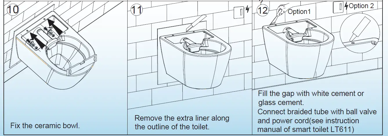
Mounting of ceramic bowl
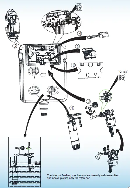
Internal flushing mechanism assembly drawing
 Thank you for using WoodBridge products!
Customer Service Phone: 562-229-0088. (Monday – Friday 9 AM – 5 PM Pacific Time) Or Email: [email protected]


