
DRAZICE OKC 400 NTRR Indirect Water Tanks
Dear Customer,
The Works Cooperative of Dražice – Machine Plant, Ltd., would like to thank you for your decision to use a product of our brand. With this guide, we will introduce you to the use, construction, maintenance and other information on electrical water heaters.
The product is not intended to be controlled by

- people (including children) with reduced physical, sensual or mental capacities, or
- people with insufficient knowledge and experiences unless supervised by responsible person, or unless properly instructed by such responsible person.
The manufacturer reserves the right for engineering modification of the product. The product is designed for permanent contact with drinkable water.
It is recommended to use the product in indoor environment with air temperatures from +2°C to +45°C and a relative humidity up to 80%.
Product’s reliability and safety is proven by tests implemented by the Engineering Test Institute in Brno. Made in the Czech Republic.
Meaning of pictograms used in the Manual
- Important information for heater users.
- Abiding by the recommendations of the manufacturer serves to ensure trouble-free operation and the long service life of the product.
- Caution!
Important notice to be observed.
PRODUCT TECHNICAL SPECIFICATION
FUNCTION DESCRIPTION
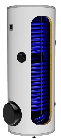
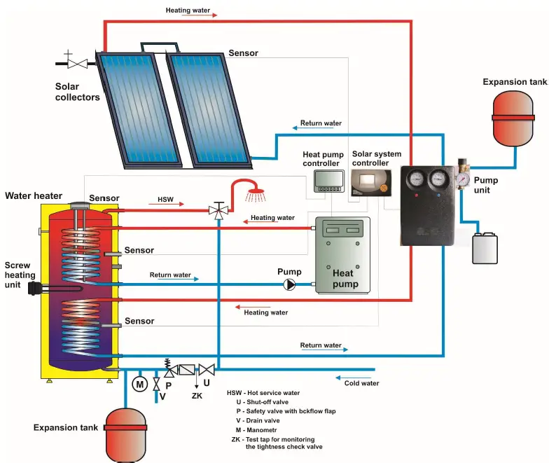
Indirect stationary tank OKC 400, 500 NTRR/HP/SOL is designed for water heating in conjunction with a heat pump. Reheat can be carried out by the electric heater TJ 6 / 4“.\
DESIGN AND BASIC DIMENSIONS OF TANK
PRODUCT DESCRIPTION
The tank receptacle is welded of steel plate and, as a unit, enamelled to resist hot water. For additional corrosion protection, 2 magnesium anodes are attached in the vessel in the upper part, adjusting the electric potential inside of the vessel interior, decreasing corrosion. Inside the vessel there are two welded spiral heat exchangers made of steel pipe with enamelled outer coating, and connections of hot and cold water, circulation and 3 brass reservoirs.
- The upper tubular heat exchanger is designed for the heating circuit, lower tubular heat exchangers is designed for solar system.
- The tank is placed on the ground, next to the heating water source, or in its vicinity. All connecting distributions must be properly insulated from heat.
On the side of the reservoir there is a cleaning and inspection aperture ending with a flange of 110 mm diameter, the pitch of eight M8 bolts is 150 mm. The reservoir is equipped with a G 1 ½ ” aperture for screwing an additional heater. This option is used, if the reservoir is connected into the system with a heat pump, for water reheating at the top of the reservoir to the desired temperature. The tank is insulated with polyurethane foam of 50 mm thickness, polyurethane foam does not contain freons. The tank shell consists of plastic container, the connecting parts are metal coated. The entire tank stands on three rectification screws with a possibility of levelling floor unevenness within the range of 10 mm. Insulation of the receptacle is 50 or 60 mm Freon – free polyurethane foam.
TECHNICAL DATA
| TYPE | OKC 400 NTRR/HP/SOL | OKC 500 NTRR/HP/SOL | |
| VOLUME | L | 352 | 469 |
| HEIGHT | mm | 1644 | 1914 |
| DIAMETER | mm | 700 | 700 |
| MAXIMUM WEIGHT WITHOUT WATER | kg | 183 | 233 |
| MAXIMUM OPERATING OVERPRESSURE IN THE VESSEL | bar | 10 | |
| MAXIMUM OPERATING OVERPRESSURE IN THE EXCHANGER* | bar | 10 | |
| MAXIMUM HEATING WATER TEMPERATURE | °C | 110 | |
| MAXIMUM OPERATING TEMPERATURE IN THE VESSEL | °C | 80 | |
| HEATING SURFACE OF UPPER/ LOWER EXCHANGER | m2 | 1,4 / 3,1 | 2 / 4,8 |
| VOLUME OF UPPER/ LOWER EXCHANGER | L | 9 / 19,3 | 12,3 / 29,7 |
| TIME OF HEATING BY EXCHANGER FROM 10°C TO 60°C (upper/ lower) | min | 22 / 32 | 27 / 26 |
| ENERGY EFFICIENCY CLASS | C | C | |
| STATIC LOSS | W | 90 | 105 |
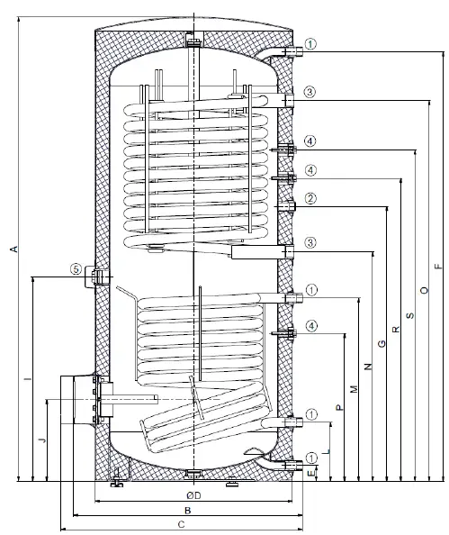
| OKC 400 NTRR/HP/SOL | |
| A | 1644 |
| B | 812 |
| C | 857 |
| D | 700 |
| E | 55 |
| F | 1521 |
| G | 973 |
| I | 723 |
| J | 288 |
| L | 208 |
| M | 648 |
| N | 812 |
| O | 1348 |
| P | 355 |
| R | 1073 |
| S | 1173 |
| | 1″ outer |
| ‚ | 3/4″ inner |
| ƒ | 5/4″ inner |
| „ | 1/2″ inner |
| … | 6/4″ inner |
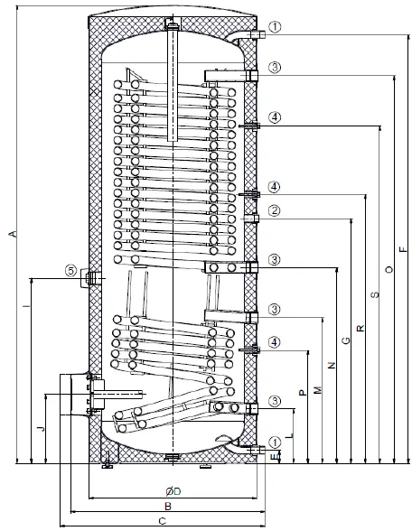
| OKC 500 NTRR/HP/SOL | |
| A | 1914 |
| B | 812 |
| C | 857 |
| D | 700 |
| E | 55 |
| F | 1790 |
| G | 1023 |
| I | 773 |
| J | 288 |
| L | 228 |
| M | 609 |
| N | 818 |
| O | 1618 |
| P | 473 |
| R | 1123 |
| S | 1409 |
| | 1″ outer |
| ‚ | 3/4″ inner |
| ƒ | 5/4″ inner |
| „ | 1/2″ inner |
| … | 6/4″ inner |
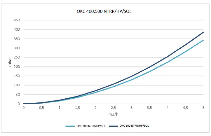
PRESSURE LOSSES
OPERATION AND FITTING INSTRUCTIONS
COMMISSIONING THE RESERVOIR
Once the tank is connected to water supply system and power supply, and the safety valve tested (accordingly with the manual attached to the valve), the tank can be put in operation. Before opening the power supply, the tank must be filled with water. The process of first heating must be executed by licensed professional who has to check it. Both the hot water outlet pipe and safety armature parts may be hot.
Procedure:
- Check the plumbing and electrical installation, including the connection to hot-water heating system. Check proper placement of operating and safety thermostat sensors. The sensors must be inserted all the way in; first the operating and then the safety thermostat.
- open the hot water valve on the combination faucet;
- Open the cold water inlet valve to the tank
- when the water starts flowing through the hot water valve, the filling of the tank is finished and the valve needs to be closed
- Should a leak (of the flange lid) occur, we recommend tightening the screws of the flange lid.
- When heating the water with thermal energy from a hot water heating system, turn off the electricity and open the valves at the inlet and outlet of heating water or bleed the exchanger. Once the operation restarts, keep flushing the tank until the cloud disappears.
- Make sure to fill in properly the warranty certificate.
CONNECTING THE RESERVOIR TO HOT WATER DISTRIBUTION
Every independently closing heater must include a shutoff, test cock, or a plug for the inspection of the backflow fitting, backflow fitting, and safety valve on the cold water supply. Heater above 200l litres is fitted with pressure gauge. It must be provided with a test valve, back valve, safety valve and manometer on the hot water inlet.
| SAFETY VALVE START-UP PRESSURE [bar] | ACCEPTABLE OPERATING OVER-PRESSURE OF WATER TANK [bar] | MAXIMUM PRESSURE IN COLD WATER PIPES [bar] |
| 6 | 6 | to 4,8 |
CONNECTION OF TANK TO HOT WATER DISTRIBUTION SYSTEM
The tank is placed on the ground, next to the heating source, or in its vicinity. The heating circuit shall be connected to marked tank exchanger inputs and outputs, and bleeder valve installed at the highest point. It is necessary to install a filter into the circuit in order to protect pumps, three-way valve, backflow flaps and the exchanger from sedimentation. It is recommended to flush the heating circuit before the assembly. All wiring connections must be properly insulated from heat. If the system works with priority heating of HUW using a three-way valve, always follow the installation instructions of the three-way valve’s manufacturer.
An example of a group tank connection for steady hot water consumption from all tanks using Tichelmann’s method
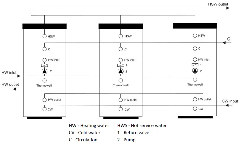
- HW – Heating water
- CV – Cold water
- C – Circulation
- HWS – Hot service water
- 1 – Return valve
- 2 – Pump
TANK CLEANING AND ANODE ROD EXCHANGE
Repetitive water heating causes limestone sediment on both the enamelled tank walls and chiefly the flange lid. Lime scale settling depends on hardness of heated water, its temperature and on the volume of hot water used.
We recommend checking and cleaning the receptacle from lime scale and eventual replacement of the anode rod after two years of operation. The anode life is theoretically calculated for two years of operation; however, it changes with water hardness and chemical composition in the place of use. Based on such an inspection, the next term of anode rod exchange may be determined. Have a company in charge of service affairs deal with the cleaning and exchanging of the anode. When draining water from the tank, the combination faucet valve for hot water must be open, preventing the occurrence of under-pressure in the tank receptacle which would stop water from draining.
To prevent the occurrence of bacteria (e.g. Legionella pneumophila) within stack heating it is recommended, if absolutely necessary, to increase the temperature of hot service water (HSW) periodically for a transitional period of time to at least 70℃. It is also possible to make use of another way of disinfecting HSW.
PROCEDURE OF EXCHANGING ANODE ROD IN UPPER PART OF THE TANK
- 1. Turn off control voltage to the tank
- Drain water from 1/5 tank.
PROCEDURE: Close water inlet in the tank
Open the hot water valve on the combination faucet.
Open the drain tap of the tank - Anode is screwed in under the plastic cover in the upper lid of the tank
- Unscrew the anode using adequate wrench
- Pull the anode out and follow reversed steps to install a new one
- During the assembly, make sure the ground wire (300 l) is connected properly; it is essential for proper anode function
- Fill the tank with water
PROCEDURE OF EXCHANGING ANODE ROD IN SIDE FLANGE
- Turn off control voltage to the tank
Drain water from the tank.
PROCEDURE: Close water inlet in the tank”
Open the hot water valve on the combination faucet. }
Open the drain tap of the tank - One anode is screwed in under the plastic cover in the upper lid of the tank, and the other one is screwed in on the side flange
- Unscrew the anode using adequate wrench
- Pull the anode out and follow reversed steps to install a new one
- Fill the tank with water
SPARE PARTS
When ordering spare parts always state the name of the part, the type and type number from the tank’s plate.
IMPORTANT NOTICES
The products have metal parts, some of which contain lead (CAS Nr. 7439-92-1) in concentrations exceeding 0.1 % by weight, or thermostats with hydrogenated terphenyl (CAS Nr. 61788-32-7) in concentrations exceeding 0.1 % by weight. These are substances which can have a very serious impact on human health and the environment. If these products are used in the prescribed manner (according to the operating instructions), and are serviced and maintained in accordance with the technical instructions and standard servicing procedures, they pose no risk to human health and the environment. Obsolete or discarded products do not belong in municipal waste. Passing them on to specialized companies licensed to accept waste or, in the case of electrical equipment, to collection points, ensures that they are processed, used and professionally disposed of in accordance with the applicable regulations, thus eliminating any risk to the environment and human health.
IMPORTANT NOTICES
Without a proof issued by a professional company about performed electrical and plumbing fixture the warranty shall be void.
It is necessary to check the protective magnesium anode periodically and replace it if necessary.
No closing armature may be mounted between the tank and the safety valve.
All outlets of hot water must be equipped with combination faucets.
Prior to the first filling the tank with water we recommend that the receptacle’s flange connection nuts are tightened.
INSTALLATION REGULATIONS
Both the electric and water installation must follow and meet the requirements and regulations relevant in the country of use!
DISPOSAL OF PACKAGING MATERIAL AND NON- FUNCTIONING PRODUCT
A service fee for providing return and recovery of packaging material has been paid for the packaging in which the product was delivered The service fee was paid pursuant to Act No. 477/2001 Coll., as amended, at EKO-KOM a.s. The client number of the company is F06020274. Take the water tank packages to a waste disposal place determined by the municipality. Disassemble the discarded and unserviceable product after the operation terminates, and transport it to a waste recycling centre (collecting yard), or contact the manufacturer.


