![]()
SigOFIT
Optical-Fiber Isolated Probe
USER MANUAL
Shenzhen Micsig Technology Co. Ltd
Preface
The information provided in this document is provided “as is” and is subject to change without notice in future editions. Further, to the fullest extent permissible pursuant to applicable law, Micsig disclaims all warranties, express or implied, with respect to this manual and any information contained herein, including, but not limited to, the implied warranties of merchantability and fitness for a particular purpose. Micsig shall not be liable for errors or for incidental or consequential damages arising out of the furnishing, use or application of this document or any information contained herein.
If a separate written agreement has been entered into between Micsig and the User that contains warranty provisions covering the contents of this document and the warranty provisions conflict with those provisions, the warranty provisions in the separate agreement shall prevail.
Contact Information
Shenzhen Micsig Technology Co., Ltd.
Tel: +86-(0)755-88600880
Address: 1F, Building A, Huafeng International Robot Industrial Park, Hangcheng Avenue, Baoan District, Shenzhen, Guangdong, China, 518126
Warranty
Micsig warrants that this product will be free from defects in materials and workmanship for a period of one (1) year from the date of shipment. If any such product proves defective in materials or workmanship during this warranty period, Micsig, at its option, either will repair the defective product without charge for parts and labor, or will provide a replacement in exchange for the defective product. Parts, modules and replacement products used by Micsig for warranty work may be new or reconditioned to like new performance. All replaced parts, modules and products become the property of Micsig.
Standard accessories are NOT covered in main body warranty.
The optical fiber bending radius of the optical isolation probe must not be less than 8cm, otherwise it will lead to fiber breakage. Damage to the fiber cable is NOT covered by the warranty.
The warranty will be void in the following cases, but repair services are provided free of labor charges and only parts are charged:
a. Damage to any accessory caused by improper use, maintenance, or storage by the consumer.
b. Damage caused by force majeure factors, such as natural disasters, etc.
Micsig will refuse to provide repair service or provide repair service for a fee in the following cases:
a. Unable to provide product packaging or anti-counterfeit labels on product packaging.
b. The content of the security label is altered, or blurred and unrecognizable.
c. Disassembled by any person not authorized by Micsig. (e.g., changing wires, disassembling internal components, etc.)
d. No sales voucher or sales voucher content does not match the product.
General Safety Summary
Please read the following safety precautions carefully to avoid personal injury and to prevent damage to this product or any equipment connected to this product.
To avoid possible hazards, be sure to use this product in accordance with the regulations.
Products are only available to personnel with relevant technical training.
To avoid fire or personal injury
Connect and disconnect properly.
Do not connect or disconnect sensor tip cables, test leads, or accessories while they are connected to a voltage source. Use only test leads and accessories supplied with the product, or indicated by Micsig to be suitable for the product.
Use only insulated voltage probes, test leads, and adapters supplied with the product, or indicated by Tektronix to be suitable for the product.
Observe all terminal ratings.
To avoid fire or shock hazard, observe all rating and markings on the product. Consult the product manual for further ratings information before making connections to the product. Do not apply a potential lowest that exceeds the maximum rating.
Do not operate without covers.
Do not operate this product with covers or panels removed, or with the case open. Hazardous voltage exposure is possible.
Do not operate with suspected failures.
If you suspect that there is damage to this product, have it inspected by qualified service personnel.
Disable the product if it is damaged. Contact Micsig’s designated service personnel to conduct the inspection.
Avoid exposed circuitry.
Do not touch exposed connections and components when power is present.
Do not operate in an explosive atmosphere.
Keep product surfaces clean and dry.
Clean with a dry cloth only.
Terms in this manual.
The following terms may appear in this manual:![]() Warning: Warning statements identify conditions or practices that could result in injury or loss of life.
Warning: Warning statements identify conditions or practices that could result in injury or loss of life.![]() CAUTION: Caution statements identify conditions or practices that could result in damage to this product or other property.
CAUTION: Caution statements identify conditions or practices that could result in damage to this product or other property.
Maintenance Safety Summary
Only qualified maintenance personnel with the relevant qualifications may perform maintenance operations. Please read the “Maintenance Safety Summary” and “General Safety Summary” before performing any maintenance operations.
Do not make repairs alone: Do not make internal repairs or adjustments to this product unless there is someone on site who can provide first aid and resuscitation measures.
Disconnect the power supply: To avoid electric shock, disconnect the power supply of the equipment first, and then disconnect the power cord from the main power supply.
Caution when servicing with electricity: Dangerous voltages or currents may be present in this product. Disconnect the power and test leads before removing the protective panel and performing soldering or component replacement.
To avoid electric shock, do not touch the exposed connectors.
Compliance Information
This section lists the Safety and Environmental standards with which the instrument complies. This product is intended for use by professionals and trained personnel only; it is not designed for use in households or by children.
Equipment type
Test and measuring equipment.
Pollution level description
A measure of the contaminants that could occur in the environment around and within a product. Typically, the internal environment inside a product is considered to be the same as the external. Products should be used only in the environment for which they are rated.
- Pollution Degree 1. No pollution or only dry, nonconductive pollution occurs. Products in this category are generally encapsulated, hermetically sealed, or located in clean rooms.
- Pollution Degree 2. Normally only dry, nonconductive pollution occurs. Occasionally a temporary conductivity that is caused by condensation must be expected. This location is a typical office/home environment. Temporary condensation occurs only when the product is out of service.
- Pollution Degree 3. Conductive pollution, or dry, nonconductive pollution that becomes conductive due to condensation. These are sheltered locations where neither temperature nor humidity is controlled. The area is protected from direct sunshine, rain, or direct wind.
- Pollution Degree 4. Pollution that generates persistent conductivity through conductive dust, rain, or snow. Typical outdoor locations.
Pollution degree rating
Pollution degree 2.
Overvoltage category descriptions
The overvoltage category is classified according to IEC60664 standard and is divided into four classes CAT I, CAT II, CAT III and CAT IV.
- Category I. Circuits not directly connected to a mains supply.
- Category II. Circuits directly connected to the building wiring at utilization points (socket outlets and similar points).
- Category III. In the building wiring and distribution system.
- Category IV. At the source of the electrical supply to the building.
Overvoltage category
Overvoltage category II
Environmental Notes
This section provides information about the environmental impact of the product.
Product end-of-life handling
When recycling instruments or components, observe the following guidelines:
Equipment Recycling: Production of this equipment required the extraction and use of natural resources. The equipment may contain substances that could be harmful to the environment or human health if improperly handled at the product’s end of life. To avoid release of such substances into the environment and to reduce the use of natural resources, we encourage you to recycle this product in an appropriate system that will ensure that most of the materials are reused or recycled appropriately.
![]() This symbol indicates that the product complies with the relevant requirements of the EU Directives 2012/96/EC and 2006/66/EC on Waste Electrical and Electronic Equipment (WEEE) and Batteries.
This symbol indicates that the product complies with the relevant requirements of the EU Directives 2012/96/EC and 2006/66/EC on Waste Electrical and Electronic Equipment (WEEE) and Batteries.
Introduction
The Micsig SigOFIT optical-fiber isolated probe offers a galvanically isolated measurement solution for accurately resolving high bandwidth, high voltage differential signals in the presence of large common mode voltages with the excellent common mode rejection capability within its bandwidth range.
Key Features:
- Exclusive SigOFIT ™ optical isolation technology, common mode voltage up to 60kVpk.
- Differential voltages up to ±2500 Vpk (attenuating tip dependent)
- CMRR up to 112dB at 100MHz and up to 100dB at 500MHz
- 1% accuracy at DC Gain
- Fast response, measurement when power-on, calibration in 1 second, delivers accurate signal output in real time
Applications:
- Power device evaluation, current parallel measurement, EMI and ESD troubleshooting
- Motor drive design, power converter design, electronic ballast design
- Design and analysis of GaN, SiC, IGBT half/full bridge devices
- Tests of inverters, UPS and switching power supplies
- Safety isolation test for high voltage, high bandwidth applications
- Wide voltage, wide band test applications
- Floating measurements
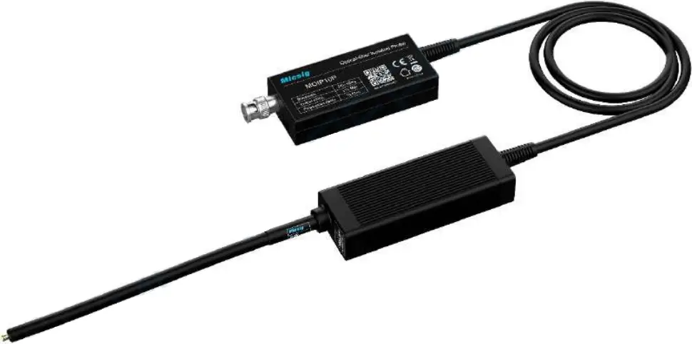
Probe description
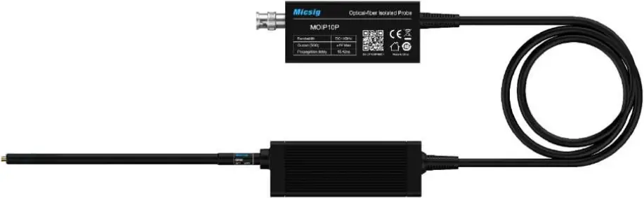
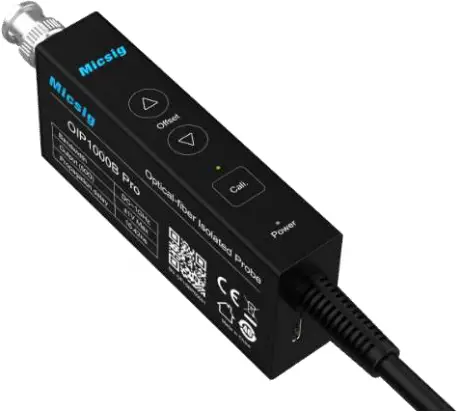
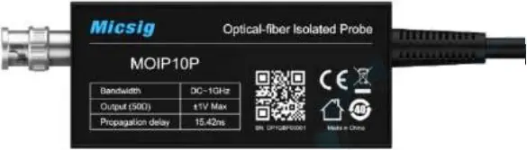
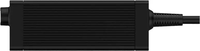
Optical-Electrical Converter
The Optical-Electrical Converter (O-E Converter herein after) can restore the optical signal transmitted by the Electrical-Optical converter (E-O Converter herein after) to an electrical signal and input to the oscilloscope. The buttons on the O-E reducer are to control the probe and the LEDs indicate the operating status of the probe.
Optical-Electrical Converter (O-E Converter)
Buttons
Cali.:
Short press to start Auto calibration, calibration time is usually less than 1 second, no need to wait. During calibration, no need to disconnect the test connection. LED will flash during calibration, the buzzer sounds one time indicates a successful calibration, three times indicates a failed calibration, press Cali. again if failed.
“△” & “▽”:
Manually adjust the Zero point (normally no adjustment is required).
Over-Voltage Alert
When the Power button LED flashes and the buzzer sounds a sharp “didididi” sound, it means the input voltage is out of range, replace the attenuating tip with suitable one to proceed.
Overheating Warning:
When the buzzer makes a “didi” sound every 2 seconds, it means that the temperature of the Optical-Electrical (O-E) converter is overheated, please check whether the dissipation port is blocked.
Electrical-Optical Converter
The Electrical-Optical (E-O) converter converts the electrical signal from device under test into an optical signal and transmits it via optic fiber to the Optical-Electrical (O-E) converter.
The E-O converter of SigOFIT probe is powered over fiber, no additional power supply required.
Electrical-Optical Converter
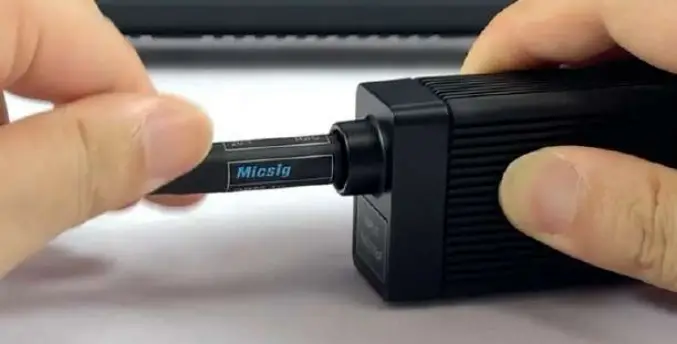
E-O converter attenuating tips
Attenuating tip options for the E-O converter end:
| Photo | Description | Model name |
| Attenuation ratio of 10:1 | OP10 | |
| Attenuation ratio of 20:1 | OP20 | |
| Attenuation ratio of 50:1 | OP50 | |
| Attenuation ratio of 500:1 | OP500 | |
| Attenuation ratio of 1000:1 | OP1000 | |
| Attenuation ratio of 2000:1 | OP2000 |
Install the attenuating tip
As shown in the figure below, screw the attenuating tip clockwise into the E-O converter end till tighten.
How to choose an attenuator:![]() Caution: Please select proper attenuator for the measurement to avoid damage to the Electrical-Optical converter or degradation of performance due to over-voltage.
Caution: Please select proper attenuator for the measurement to avoid damage to the Electrical-Optical converter or degradation of performance due to over-voltage.
Please select the attenuating tip with the lowest attenuation ratio allowed by the tested signal range.
Considerations when selecting an attenuator:
- What is the peak voltage (or RMS voltage) of the signal under test?
- What is the minimum differential load (input resistance) that the circuit can accept?
- How big the signal needs to be displayed on the oscilloscope?
- What is the minimum vertical scale (V/div) to be observed?
Please refer to the technical Datasheet to select the appropriate attenuator (on E-O converter end).
Precaution requirements
Measurement System Precautions
SigOFIT probe contains high quality components and should be handled with care to avoid damage or degradation of performance due to improper handling. Please consider the following precautions when handling fiber optic cable and electrical-to-optical converter end connections:
![]()
- DO NOT excessively bend fiber-optic cable. Avoid tight radius (8cm) bends, crushing, crimping, twisting, pulling or otherwise stressing cables.
- DO NOT block the heat dissipation port on the Optical-Electrical converter (or O-E Converter), otherwise the probe may be overheated and damaged.
- Do not put heavy objects on the fiber cable, such as running over with a chair.
- When disassembling and moving the probe, please hold the converter body by hand, do not lift or drag the cable.
- Fiber cable bending radius should not be less than 8 cm.
- Accidental drop of the E-O or the O-E converter may result in damage to internal optical components.
- Please check damage to the fiber cable, (as shown below) please stop use when there is damage to the flexible braided cable or the soft rubber sheath.
- When not in use, store the SigOFIT probe in its factory fitted carrying case.
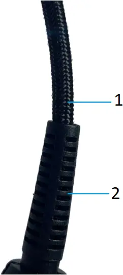
- flexible braided cable
- soft rubber sheath
Environmental requirements
Features | Status | Environmental requirements |
| Temperature | Working | Optical-Electrical converter: 0°C ~ +40°C |
Electrical-Optical converter: 0°C ~ +40°C | ||
| Non-working | Optical-Electrical converter: -20°C ~ +70°C | |
Electrical-Optical converter: -20°C ~ +70°C | ||
| Humidity | Working | Optical-Electrical converter: 5% to 85% RH (relative humidity) below +30°C, non-condensing |
| Electrical-Optical converter: 5% to 85% RH (relative humidity) below +40°C; 5% to 45% RH at +40°C ~ +50°C, non-condensing | ||
Non-working | Optical-Electrical converter: 5% to 85% RH below +40°C; 5% to 45% RH at +40° C ~ +85°C, non-condensing | |
| Electrical-Optical converter: 5% to 85% RH below +40°C; 5% to 45% RH at +40° C ~ +85°C, non-condensing | ||
Altitude | Working | 3000 meters |
| Non-working | 12,000 meters |
Safety requirements
Please read and understand all precautions when using this product.
![]() Warning: Electric shocks may occur when using this measurement system. The system is used to isolate the personnel from dangerous input voltages (common voltage); the plastic housing of the Electrical-Optical converter and the shielding of the attenuator do not provide safe isolation.
Warning: Electric shocks may occur when using this measurement system. The system is used to isolate the personnel from dangerous input voltages (common voltage); the plastic housing of the Electrical-Optical converter and the shielding of the attenuator do not provide safe isolation.
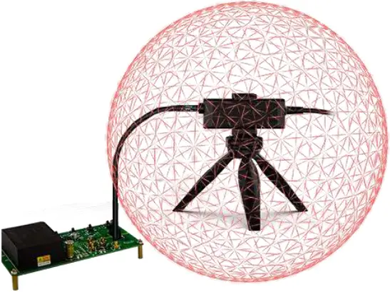
Keep a safe distance from the Electrical-Optical converter and the attenuator when the measurement system is connected to an energized circuit as recommended in this manual. When making measurements on energized circuits, do not touch radio frequency burn hazard area.
When measuring high-frequency common-mode signals, there is a risk of RF burns. Please refer to the following descending curve to determine the danger areas. Measuring common-mode signals within the purple area within 1 meter of the E-O converter and earth ground may result in RF burns.
![]() Burn limit
Burn limit ![]() common mode voltage (Vpk)
common mode voltage (Vpk) ![]() common mode voltage (Vrms)
common mode voltage (Vrms)
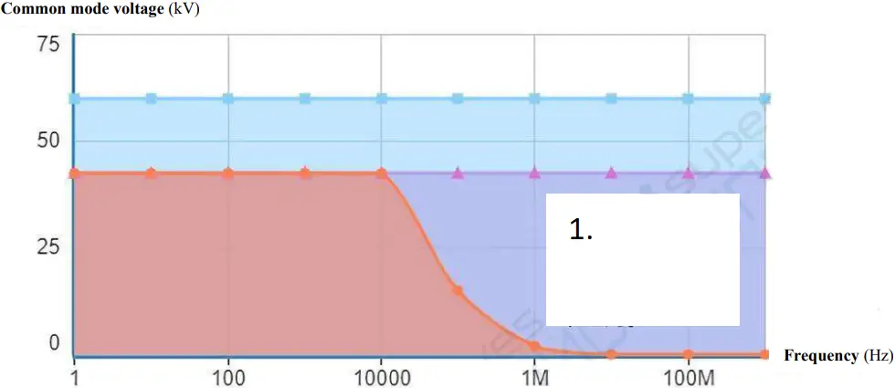
Maximum safe handling limits for common mode voltages between E-O converter and earth ground
- RF Burn Risk Area
1 m (40 in) Away
From E-O converter
The following diagram shows the components of the measurement system and the possible RF burning area when operating with dangerous voltages. 1 m RF burn area is indicated by the red sphere around the electrical-optical converter:
Installation
![]() Warning: Do not disassemble the electrical-optical converter or the optical-electrical converter. They contain a laser source which may result in laser exposure.
Warning: Do not disassemble the electrical-optical converter or the optical-electrical converter. They contain a laser source which may result in laser exposure.![]() Warning: To avoid the risk of electric shock, do not connect the measurement system directly to an energized circuit. Always disconnect the test circuit before installing or removing the attenuating tip from the test circuit. The plastic housing the converter and the shielded end of the attenuator do not provide isolation.
Warning: To avoid the risk of electric shock, do not connect the measurement system directly to an energized circuit. Always disconnect the test circuit before installing or removing the attenuating tip from the test circuit. The plastic housing the converter and the shielded end of the attenuator do not provide isolation.![]() Warning: To avoid the risk of electric shock or RF burn when the circuit under test is energized, do not touch the electrical-optical converter and its attenuator while testing. Always maintain a distance of 1 meter or more from the electrical-optical converter during the test. Be sure to review the instrument’s maximum ratings and derating curves for more information on RF burn areas.
Warning: To avoid the risk of electric shock or RF burn when the circuit under test is energized, do not touch the electrical-optical converter and its attenuator while testing. Always maintain a distance of 1 meter or more from the electrical-optical converter during the test. Be sure to review the instrument’s maximum ratings and derating curves for more information on RF burn areas.![]() Warning: To avoid possible damage to the device, do not connect the probe of the electrical-optical converter connection to a high impedance part of the circuit. Additional capacitance may cause damage to the circuit. Please connect the probe connected to the electrical-optical converter to the low impedance part of the circuit. Note: Touching the electrical-optical converter or attenuator while measuring high frequency common mode signals will increase capacitive coupling and may reduce the common mode loading of the test circuit.
Warning: To avoid possible damage to the device, do not connect the probe of the electrical-optical converter connection to a high impedance part of the circuit. Additional capacitance may cause damage to the circuit. Please connect the probe connected to the electrical-optical converter to the low impedance part of the circuit. Note: Touching the electrical-optical converter or attenuator while measuring high frequency common mode signals will increase capacitive coupling and may reduce the common mode loading of the test circuit.![]() Warning: To prevent arc flash caused by different potentials, do not place the electrical-optical converter end attenuator in a circuit with different voltages.
Warning: To prevent arc flash caused by different potentials, do not place the electrical-optical converter end attenuator in a circuit with different voltages.
Operation Steps
1. Connect the optical-electrical converter to the oscilloscope;
2. Set the oscilloscope input impedance to 50 Ω, set the corresponding attenuation ratio and delay time;
3. Connect the attenuator to the electrical-optical converter;
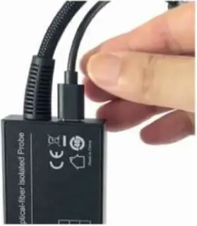
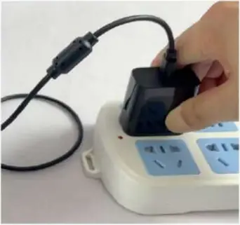
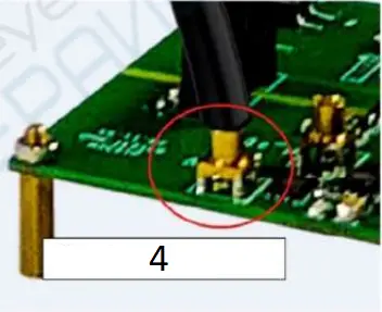
4. Use standard USB Type-C cable to power the O-E Converter (Figure 3), the E-O Converter will be powered on automatically, vice versa, when the O-E converter powered off, the E-O converter will be powered off simultaneously.
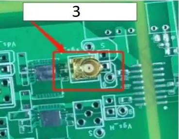
5. Weld the MCX connector to the test board.
Notice:
1) When testing Vgs signal, the signal pin (on the center) of the MCX connector must be connected to the Grid end of the MOSFET;
2) Weld the MCX connector directly to the test point, try NOT to use extension lead, it could have a great impact on the test results.
3) For the convenience of welding, cut off three of the four pins around the base (as shown in Figure 4), just keep one, show as below figure.
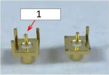
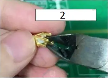
- Signal Tip
- Cut 3 pins off 4
- Weld MCX to test board
- Plug in test tip
6. Plug the attenuating into the MCX socket; when hearing a “click”, it means that the connection is successful.
7. Power ON the test board;
8. Adjust the oscilloscope settings and proceed normal test;
Auto calibration and manual Zero
The SigOFIT probe has an auto-calibration function that automatically corrects the gain accuracy. When you want to get more accurate results, press the Cali. button to perform a calibration operation. There is no need to disconnect the test connection during calibration. Auto calibration complete in less than 1 second.
The SigOFIT probe allows manual adjustment of DC offset.
The Zero and calibration functions are applied to different parts of the measurement system. The calibration function optimizes the measurement by adjusting the probe parameters. Zero is a function used when the waveform is not properly centered (e.g., due to small DC offset errors).
Press the “△” and “▽” buttons on the E-O converter to adjust the zero point manually, no adjustment is needed in general.
Technical Specifications
All technical specifications are typical values unless otherwise indicated.
Technical specifications are valid when:
- Probe is calibrated at 23°C ±5°C ambient temperature
- Probe is powered by normal power supply
- The temperature, altitude, and humidity of the environment in which the probe is located cannot exceed the limits of the stated environmental requirements
Electrical Characteristics
Model & Ordering Name | MOIP01P | MOIP02P | MOIP03P | MOIP05P | MOIP08P | MOIP10P |
| Bandwidth | 100MHz | 200 MHz | 350 MHz | 500 MHz | 800 MHz | 1 GHz |
Rise time | ≤3.5ns | ≤1.75n | ≤1ns | ≤700ps | ≤438ps | ≤350ps |
| Output Voltage | ±2.5V | ±1.25V | ||||
Differential Voltage Range | 1X:±2.5V 10X:±25V 20X:±50V 500X:±1250V 1000X:±2500V | 1X:±1.25V 20X:±25V 50X: ±62.5V 1000X:±1250V 2000X:±2500V | ||||
| System noise (rms) | <1.41mVrms | |||||
SMA Input Impedance | 1MΩ || 10pF | |||||
| Propagation delay | 15.42ns (2m) | |||||
Power supply | USB Type-C, DC: 5V | |||||
| DC Gain accuracy | 1% | |||||
Common mode voltage range | 60kVpk | |||||
| Fiber cable length | 2m (Customizable) | |||||
Attenuator ratio, input impedance
Probe Tip | Attenuation | Input impedance |
| SMA Input | 1X | 1MΩ || 10pF |
OP10 Input | 10X | 10MΩ || 3.0pF |
| OP20 Input | 20X | 9.47MΩ || 2.8pF |
OP50 Input | 50X | 9.47MΩ || 2.8pF |
| OP500 Input | 500X | 12.27MΩ || 2.6pF |
OP1000 Input | 1000X | 12.28MΩ || 2.6pF |
| OP2000 Input | 2000X | 30MΩ || 1pF |
Common mode rejection ratio
Probe | DC | 1MHz | 100MHz | 200MHz | 350MHz | 500MHz | 800MHz | 1GHz |
| SMA | 160dB | 152dB | 112dB | 106dB | 102dB | 100dB | 94dB | 92dB |
OP10 | 160dB | 120dB | 96dB | 92dB | 90dB | 86dB | 84dB | 82dB |
| OP20 | 160dB | 120dB | 92dB | 90dB | 86dB | 84dB | 82dB | 80dB |
OP50 | 160dB | 115dB | 86dB | 82dB | 80dB | 78dB | 75dB | 74dB |
| OP500 | 160dB | 96dB | 56dB | 48dB | 40dB | 32dB | 28dB | 26dB |
OP1000 | 160dB | 90dB | 50dB | 42dB | 34dB | 26dB | 22dB | 20dB |
| OP2000 | 160dB | 90dB | 50dB | 42dB | 34dB | 26dB | 22dB | 20dB |
Mechanical characteristics
| Characteristics | Parameters |
| Optical- Electrical converter size | 9.8*4.5*2.1 cm |
| Electrical-optical converter size | 11*4*2.3 cm |
| Fiber cable length (Optical-electrical converter to electrical-optical converter) | 2 m |
Amplitude and frequency characteristics curve
MOIP05P Amplitude-frequency characteristics curve
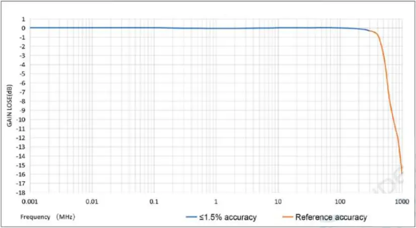
Amplitude – frequency characteristics curve of SigOFIT MOIP05P probe.
Maintenance Service
This section provides information on the maintenance of the SigOFIT probe.
Troubleshooting
The LED light indicate working states of the SigOFIT probe, if the Green light is not ON, possible problems that you might encounter when taking measurements. Use the tables as a quick troubleshooting reference before contacting Micsig for service.
| Failure phenomenon | Possible causes and solutions |
| Signal amplitude does not match as expected |
|
| DC measurement error exists |
|
| Big noise, unable to accurately measure weak signal |
|
| No signal is captured and the waveform is a straight line at the zero point |
|
Maintenance
Do not expose the probe to harsh weather conditions, the probe is not waterproof.
![]() Note: The probe is not waterproof and to prevent damage to the probe, do not expose it to sprays, liquids or solvents. Avoid wetting the inside when performing exterior cleaning of the probe.
Note: The probe is not waterproof and to prevent damage to the probe, do not expose it to sprays, liquids or solvents. Avoid wetting the inside when performing exterior cleaning of the probe.
Do not wipe the probe with chemical cleaners.
Clean the outer surface of the probe with a dry, non-linting soft cloth or a soft bristle brush.
When not in use, store the SigOFIT probe in the suitcase provided by Micsig.
Ordering Information
Models
MOIP01P Micsig SigOFIT 100MHz, Optical-fiber Isolated Probe, 2-meter cable
MOIP02P Micsig SigOFIT 200MHz, Optical-fiber Isolated Probe, 2-meter cable
MOIP03P Micsig SigOFIT 350MHz, Optical-fiber Isolated Probe, 2-meter cable
MOIP05P Micsig SigOFIT 500MHz, Optical-fiber Isolated Probe, 2-meter cable
MOIP08P Micsig SigOFIT 800MHz, Optical-fiber Isolated Probe, 2-meter cable
MOIP10P Micsig SigOFIT 1GHz, Optical-fiber Isolated Probe, 2-meter cable
Standard Accessories
MCX connector (2.54mm) *5 Connecting SigOFIT and the circuit under test
MCX connector (5.08mm) *5 Connecting SigOFIT and the circuit under test
MCX coaxial cable *1 Connecting SigOFIT and the circuit under test
Carrying Case *1 Case with EVA foam
Probe Mount *1 Bipod mount to support probe head
USB type-C to type-C cord *1 To power the Optical-Electrical Converter
25W USB charger *1 To power the Optical-Electrical Converter
Optional Accessories
OP10-x Attenuator tip of 10X
OP20-x Attenuator tip of 20X
OP50-x Attenuator tip of 50X
OP500-x Attenuator tip of 500X
OP1000-x Attenuator tip of 1000X
OP2000-x Attenuator tip of 2000X
Remarks:
OPXX-* is attenuator tip, XX means attenuation ratio, * means bandwidth.
i.e, OP10-2 is an attenuator tip with 10X, bandwidth of 200MHz.
Refer to following list to choose applicable attenuator tip:
Model No. | Standard Tip(s) | Optional Tip(s) | Customizable Tip(s) |
| MOIP01P | OP10-2¹ | OP20-2 OP500-2 OP1000-2 | 50X, 200X … (Different attenuation multiples can be customized according to actual needs) |
MOIP02P | |||
| MOIP03P | OP20-5 OP1000-5 | OP50-5 OP2000-5 | 10X, 500X … (Different attenuation multiples can be customized according to actual needs) |
MOIP05P | |||
| MOIP08P | OP20-1G OP1000-1G | OP50-1G OP2000-1G | |
MOIP10P |
Supported Oscilloscopes
All BNC interface, with 50 impedance oscilloscope
After Sales Service / Service Support
Optical-fiber Isolated Probe main body warranty for 1 year (extendable with extra charge).
The SigOFIT probe contains high-quality components and should be treated with care, Damage to the fiber optic cable is NOT covered by the warranty.
Standard accessories are NOT covered in main body warranty.
Micsig provides one-on-one exclusive technical support service.
During the warranty period, Micsig will be responsible for providing free maintenance for any malfunctions caused by quality issues within the normal use of the product that have not been disassembled or repaired.
The warranty will be invalid in the following cases, but repair services can be provided, free of labor costs, and only parts fees will be charged:
a. Any damage to accessories caused by improper use, maintenance, or storage by consumers.
b. Damage caused by force majeure factors, such as natural disasters.
Micsig will refuse to provide repair services or provide paid repair services in the following situations:
a. Unauthorized dismantling, such as changing wires, dismantling internal components, etc.
b. No sales voucher or the content of the sales voucher does not match the product.
* Micsig reserves the right of final interpretation for the content hereinabove;
* It is subject to update without prior notice;
* Please contact local distributor for any inquiry or send us email directly.
![]()
Shenzhen Micsig Technology Co., Ltd.
Add: 1F, Bldg A, Huafeng International Robot Industrial Park, Hangcheng Rd, Bao’an District, Shenzhen, Guangdong, China
TEL: +86-(0)755-88600880 Email: [email protected] Web: www.micsig.com


