KRAMER 691 Fiber Optic Transmitter
 | This guide helps you install and use your 691/692 for the first time. Go to www.kramerav.com/downloads/691 or www.kramerav.com/downloads/692 to download the latest user manual and check if firmware upgrades are available. |
Check what’s in the box
- 691 HDBT 2.0 Transmitter or 692 HDBT 2.0 Receiver
- 1 OSP-MM1 Fiber Optic SFP+ Transceiver
- 1 Power adapter and cord
- 1 Quick start guide
- 4 Rubber feet
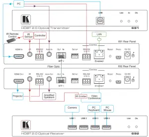
Get to know your 691/692
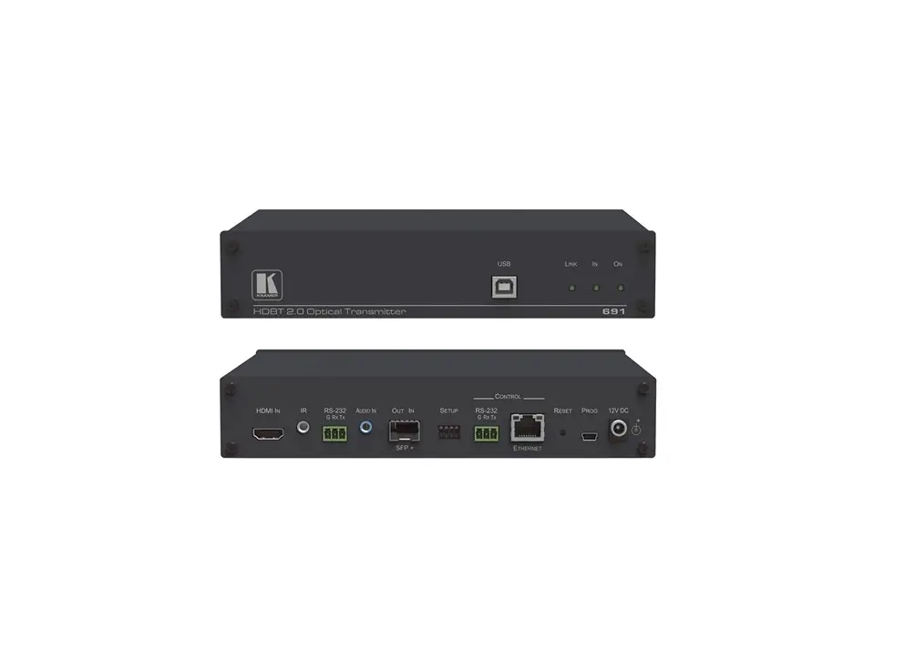
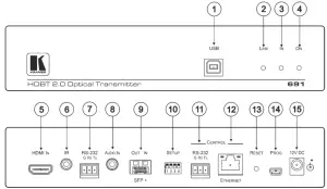
691
| # | Feature | Function | |
| 1 | USB Connector | Connect to the USB host (for example, a laptop) for traffic extension to remote connected USB devices. | |
| 2 | LINK LED | Lights green when the HDBT link is active. | |
| 3 | IN LED | Lights green when an active HDMI source is connected. | |
| 4 | ON LED | Lights green when the device receives power. | |
| 5 | HDMI IN Connector | Connect to the HDMI source. | |
| 6 | IR 3.5mm Mini Jack Connector | Connect to an external infrared transmitter or receiver for traffic extension. | |
| 7 | RS-232 3-pin Terminal Block | Connect to an RS-232 controller for traffic extension (for example, a PC to control the projector). | |
| 8 | AUDIO IN 3.5mm Mini Jack | Connect to the stereo, analog audio source. | |
| 9 | OUT IN SFP+ Connector | Connect the fiber optic cable to the OUT IN SFP+ connectors (OSP-MM1 included). | |
| 10 | SETUP 4-way DIP-switch | Sets the device functions. | |
| 11 | CONTROL | RS-232 3-pin Terminal Block | Connect to the serial controller to control this device. |
| 12 | ETHERNET RJ-45 Connector | Connect to the LAN to extend network traffic to the receiver and Ethernet controller to control this device. | |
| 13 | RESET Switch | Press and hold for 5 seconds to reset the device to factory default settings. Press and immediately release to power-cycle the device (Reset). | |
| 14 | PROG Mini USB Connector | Connect to a PC to perform firmware upgrades. | |
| 15 | 12V DC Power Connector | Connect to the supplied power adapter. | |
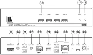
692
| # | Feature | Function | |
| 16 | USB Connectors | Connect to the USB devices (for example, a camera, keyboard, mouse and so on) for traffic extension to a remote connected USB host. | |
| 17 | LINK LED | Lights green when the HDBT link is active. | |
| 18 | ON LED | Lights green when the device receives power. | |
| 19 | HDMI OUT Connector | Connect to the HDMI acceptor. | |
| 20 | IR 3.5mm Mini Jack Connector | Connect to an external infrared transmitter or receiver for traffic extension. | |
| 21 | RS-232 3-pin Terminal Block | Connect to an RS-232 Controller for traffic extension (for example, a PC to control the Blu-ray player on the transmitter side). | |
| 22 | AUDIO OUT 3.5mm Mini Jack | Connect to the stereo, analog audio acceptor. | |
| 23 | OUT IN SFP+ Connector | Connect the fiber optic cable to the OUT IN SFP+ connectors (OSP-MM1 included). | |
| 24 | SETUP 4-way DIP-switch | Sets the device functions. | |
| 25 | CONTROL | RS-232 3-pin Terminal Block | Connect to the serial controller to control this device. |
| 26 | ETHERNET RJ-45 Connector | Connect to the LAN to extend network traffic to the transmitter and Ethernet controller to control this device. | |
| 27 | RESET Switch | Press and hold for 5 seconds to reset the device to factory default settings. Press and immediately release to power-cycle the device (reset). | |
| 28 | PROG Mini USB Connector | Connect to a PC to perform firmware upgrades. | |
| 29 | 12V DC Power Connector | Connect to the supplied power adapter. | |
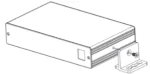
Mount 691/692
Install 691/692 using one of the following methods:
- Attach the rubber feet and place the unit on a flat surface.
- Fasten a bracket (included) on each side of the unit and attach it to a flat surface
(see www.kramerav.com/downloads/691). - Mount the unit in a rack using the recommended rack adapter
(see www.kramerav.com/product/691).
 |
|
Connect inputs and outputs
Always switch OFF the power on each device before connecting it to your 691/692. For best results, we recommend that you always use Kramer high-performance cables to connect AV equipment to the 691/692.
![]() For optimal performance, use the RECOMMENDED Kramer cables available at www.kramerav.com/product/691.
For optimal performance, use the RECOMMENDED Kramer cables available at www.kramerav.com/product/691.
Using third-party cables may cause damage!
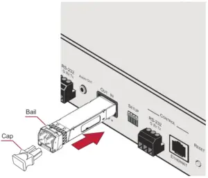
To install/replace the OSP-MM1 or other Kramer recommended SFP+ transceiver:
- Pull the bail out and remove the currently installed transceiver, insert the protective cap and store in a safe place.
- Make sure the bail of the new transceiver is pushed up, in the closed position.
- Insert the new transceiver into the relevant optical device SFP+ slot and push it in until it clicks.
- Remove the protective cap and store it in a safe place for future use

Warning: Connecting the OSP SFP+ connector to an LC(APC) fiber connector may cause poor performance and damage the connector!
Refer to www.kramerav.com/downloads/691 for more information.
Warning: Class 1 Laser Product
- Invisible laser radiation present.
- Avoid long-term viewing of laser.
- Avoid the use of magnifying viewing aids or instruments (such as binoculars, telescopes, microscopes and magnifying lenses, but not spectacles or contact lenses).
- Avoid placing optical devices in the emitted beam that could cause the concentration of the laser radiation to be increased.
SETUP DIP-Switches
A DIP-switch that is down is on, up is off. Changes to the DIP-switches only take effect on power-up. After changing a switch, reboot the device.
| # | Function | Applicable to: | Status |
| 1 | For future use | 691 and 692 | — |
| 2 | Audio source priority | 691 only | Off—Embedded audio (factory default) On—Analog audio |
| 3 | EDID lock | 691 and 692 | Off—Automatic EDID acquisition (factory default) On—Lock (locks the current EDID so that changes on the output do not result in changes to the EDID) |
| 4 | Audio mode selection | 691 only | Off—Auto (factory default) On—Manual |
Connect power
Connect the power cord to 691/692 and plug it into the mains electricity.
Safety Instructions (See www.kramerav.com for updated safety information)
Caution:
- For products with relay terminals and GPI\O ports, please refer to the permitted rating for an external connection, located next to the terminal or in the User Manual.
- There are no operator serviceable parts inside the unit.
Warning:
- Use only the power cord that is supplied with the unit.
- Disconnect the power and unplug the unit from the wall before installing
Operate 691/692
Embedded Web pages: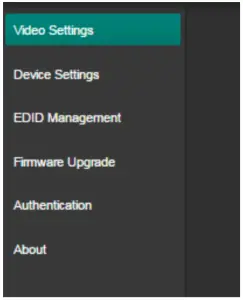
Embedded Web pages: RS-232 and Ethernet parameters and defaults:
| RS-232 | |||
| Protocol 3000 | |||
| Baud Rate: | 115,200 | Stop Bits: | 1 |
| Data Bits: | 8 | Parity: | None |
| Command format: | ASCII | ||
| Example (get device model name): | #model?<cr> | ||
| TCP/IP | |||
| IP Address: | 192.168.1.39 | UDP Port #: | 50000 |
| Subnet mask: | 255.255.000.000 | TCP Port #: | 5000 |
| Default gateway: | 192.168.0.1 | ||
| Embedded Webpages Authentication | |||
| User/Password | Admin/Admin | ||
| Full Factory Reset | |||
| Rear panel button: | Press and hold for 5 seconds to reset the device to factory default settings. | ||
| P3K command: | #factory<cr> | ||
| Embedded Web pages: | Select Device Settings page and click Factory reset | ||
The terms HDMI, HDMI High-Definition Multimedia Interface, and the HDMI Logo are trademarks or registered trademarks of HDMI Licensing Administrator, Inc.