STAHL 209268 Pac Carrier
WebCode 9195A
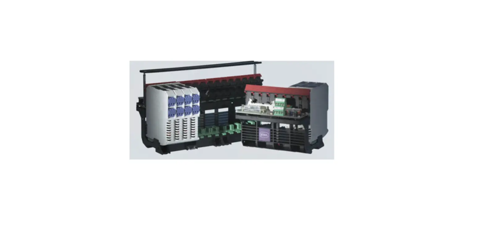
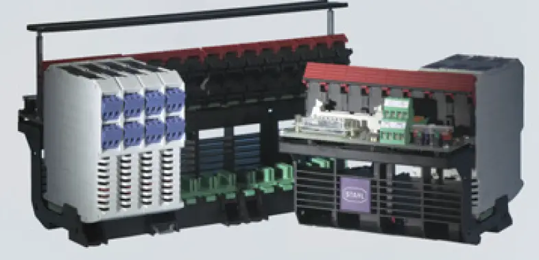
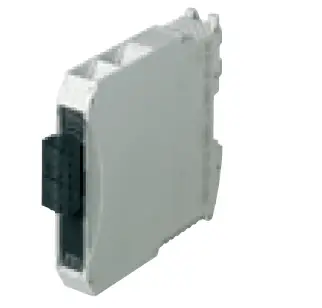
The 9195 series pac- Carrier is a cost- effective solution allowing Ex i field devices to be connected to common I/ O modules of distributed control systems and programmable logic controllers. The extremely robust carrier is suitable for 8 or 16 standard ISpac isolators and can process 32 signals, including a combination of Ex i and non- Ex i signals. It can be adapted to accommodate new I/ O modules at any time. The carrier can be combined with the 9192 series HART Mux
- Prefabricated system cables for field terminal boards (FTB) make it quick and easy to install – simply snaps onto a DIN rail or mounting plate
- Can be used with the Emerson Delta V, Schneider Foxboro/ Tricon, Honeywell C300, Siemens ET200M and ET200F, Yokogawa Centum VP and ProSafe- RS
- All ISpac isolators 91xx can be used in the pac- Carrier
Technical Data
| Explosion Protection | |
| Application range (Zones) | 2 |
| IECEx gas certificate | IECEx BVS 10.0042 X |
| IECEx gas explosion protection | Ex ec nC IIC T4 Gc |
| ATEX gas certificate | BVS 03 ATEX E 213 X |
| ATEX gas explosion protection | E II 3 G Ex ec nC IIC T4 Gc |
| FMus certificate | FM16US0122X |
| cFM certificate | FM16CA0067X |
| Marking cFMus | Class I, Div. 2, Groups A,B,C,D; Class I, Zone 2, Group IIC T4 at Ta = 70°C See Doc. 91 956 01 31 1 |
| EAC certificate | EAES_RU_S-DEHA91B00100_20 |
| EAC gas explosion protection | 7 2 Ex nA nC IIC T4 Gc X |
| Certificates | ATEX (BVS), Brazil (ULB), Canada (FM), EAC (ENDCE), IECEx (BVS), India (PESO), SIL (exida), USA (FM) |
| Ship approval | CCS, EU RO MR (DNVGL) |
| Notes | CCC, UKCA certificate available from 2022 onward |
| Functional Safety | |
| SIL | 3 |
| Electrical Data | |
| Type of signal | DI, DO, AI, AO |
| Number of channels | 32 |
| LFD relay | Yes |
| I/O type | any |
| Redundancy | No |
| Connections | HART interface via HART multiplexer 9192 |
| Electrical Data | |
| HART-multiplexer connection | Yes |
| Number of channels field device interface (HART) | 8,16, 32 |
| Fuse | 2 x TR5; T 2 A; exchangeable, for primary and redundant supply |
| Auxiliary Power | |
| Auxiliary power | 24 V DC |
| Nominal voltage Vnom | 24 V DC |
| Redundant supply | yes, decoupled with diodes |
| Polarity reversal protection | Yes |
| Input | |
| Line fault and loss of power signalization | Contact (30 V / 100 mA) closed to ground in case of fault pac-Bus, floating contact (30 V / 100 mA) |
| Output | |
| Fault message contact switching capacity | 30 V / 100 mA |
| Ambient Conditions | |
| Ambient temperature °C | -20 °C … +70 °C |
| Ambient temperature °F | -4°F … +158°F |
| Storage temperature °C | -40 °C … +80 °C |
| Storage temperature °F | -40°F … +176°F |
| Max. relative humidity | 95% |
| Use at the height of | < 2000 m |
| Electromagnetic compatibility | Tested to the following standards and regulations: EN 61326-1 Use in industrial environ- ment; NAMUR NE 21 |
| Mechanical Data | |
| Degree of protection (IP) | IP00 |
| Number of slots | 16 |
| Grid dimension | 17.6 mm |
| Width | 292 mm |
| Width, inches | 11.5 in |
| Height | 150 mm |
| Height, inches | 5.91 in |
| Length | 155 mm |
| Length, inches | 6.1 in |
| Weight | 0.843 kg |
| Weight | 1.86 lb |
| Construction drawing | |
| 1. Carrier for 8 or 16 modules (32 channels) 2. Labeling for module, slot and carrier 3. Ejector mechanism (with screw driver) 4. Redundant and fused supply 5. Power supply failure and line fault signalling via relay 6. System specific PCB 7. System specific plugs 8. Signal duplication and / or connection HART-Multiplexer 9. For hat-rail or mounting plate 10. Integrated pac-Bus for power supply and line-fault signalling 11. Secure snap-in mechanism, without tool 12. Single slot, any signal mixture | |
| Mounting / Installation | |
| Mounting type | DIN rail or wall mounting |
| Mounting orientation | horizontal or vertical |
| Mounting orientation | Vertical Horizontal |
| Connection type | Screw terminal |
| Min. rigid conductor cross section | 0.14 mm² |
| Max. rigid conductor cross section | 1.5 mm² |
| Min. flex conductor cross section | 0.14 mm² |
| Max. flex conductor cross section | 1.5 mm² |
| Connection cross-section AWG | 28 – 16 |
Technical Drawings
Subject to Alterations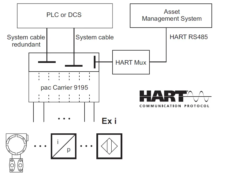
Dimensional Drawings
(All Dimensions in mm [inches]) – Subject to Alterations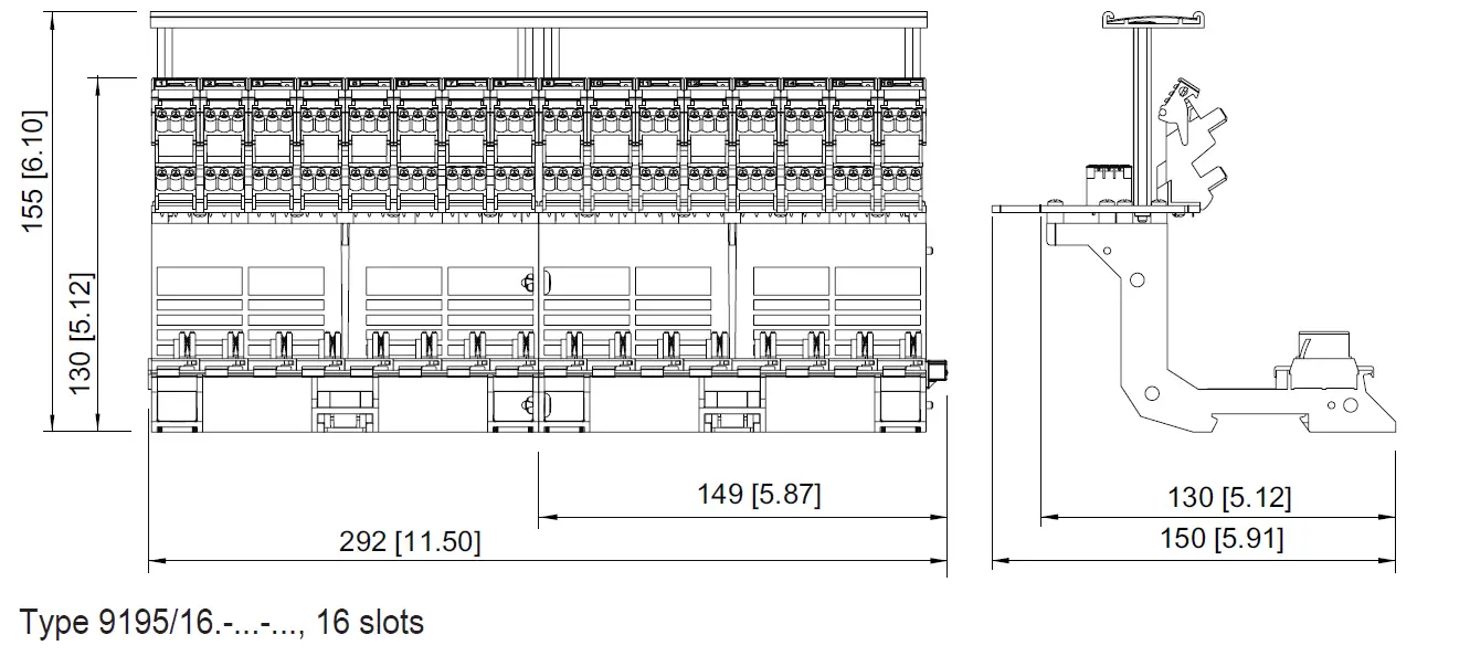
Accessories
Noni- Ex I termination module
| Non-Ex i termination | module | Art. No. |
 | The termination module is used to integrate non-Ex i field circuit into the system integration solution pac-carrier type 9195. In such a way it enables a flexible mixture of Ex i and non-Ex i field circuits. | 165683 |
We reserve the right to make alterations to the technical data, dimensions, weights, designs and products available without notice. The illustrations cannot be considered binding
R. STAHL, INC
13259 N. Promenade Blvd.
Stafford, TX 77477
Tel. +1 800 782 4357
US Email US: [email protected]
Email CAN: [email protected]
rstahl.com


