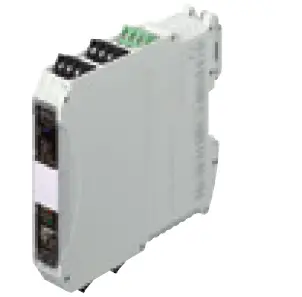
STAHL 9419/08R-XX1-02C1 Isbus Fieldbus Technology Bus-Carrier
WebCode 9419A
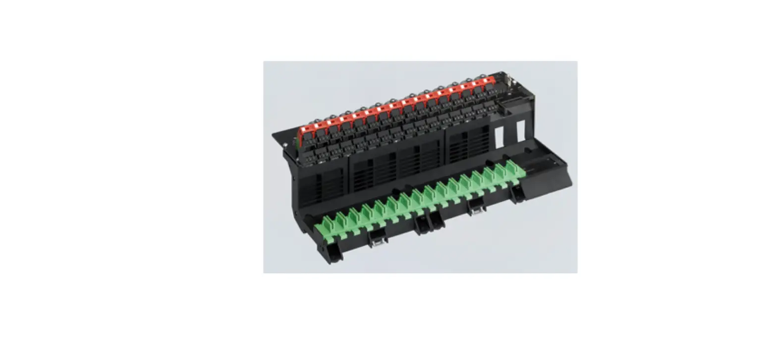
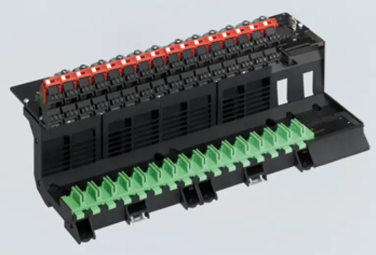
9419 series bus carriers allow 9412 series fieldbus power supplies for FF H1 segments to be installed quickly and securely. Variants are available for eight segments with simplex supply and for four or eight segments with redundant supply. Pluggable terminals are used to connect the fieldbus segments and host assemblies
- Time- and cost- saving installation on DIN rails or mounting plates
- High availability thanks to redundant auxiliary power supply with signalling contact and separate signalling contact for segment errors
- Special slot for 9415 series DCM for online transmission of physical layer diagnostics
Technical Data
| Explosion Protection | |
| Application range (Zones) | 2 |
| IECEx gas certificate | IECEx BVS 09.0042X |
| IECEx gas explosion protection | Ex nA nC IIC T4 Gc |
| ATEX gas certificate | BVS 09 ATEX E 100 X |
| ATEX gas explosion protection | E II 3 G Ex nA nC IIC T4 Gc |
| FMus certificate | 3026646 |
| cFM certificate | 3026646C |
| Marking cFMus | Nonincendive for, Class I, Div. 2, Groups A,B,C,D; T4, at Ta = 70 °C Class I, Zone 1, AEx/Ex nA nC IIC T4 , at Ta = 70 °C 9419 6 031 001 1 |
| EAC certificate | TS RU S-DE.ME92.B.01076 |
| EAC gas explosion protection | 7 2 Ex nA nC IIC T4 Gc X |
| Certificates | ATEX (BVS), Brazil (ULB), Canada (FM), EAC (ENDCE), IECEx (BVS), India (PESO), USA (FM) |
| Electrical Data | |
| Version | bus‐Carrier, universal |
| Connection electrical data | To any FF H1 host |
| Trunk supply | Redundant |
| Number of segments | 8 |
| Number of slots | 16 FPS + 1 DCM |
| Error detection Power Fail (pri / red) | Contact “PF” (35 V/100 mA) closed in go-state |
| Error detection Diagnostic | Contact “Dia” (35 V/100 mA) closed in go-state |
| Auxiliary Power | |
| Nominal voltage Vnom | 24 V DC |
| Auxiliary power voltage range | 19 to 32 V DC |
| Voltage range residual ripple | ≤ 3,6 Vss |
| Current consumption | Depending on support equipment |
| Auxiliary Power | |
| Redundant supply | Yes, diode-decoupled |
| Polarity reversal protection | Yes |
| Power dissipation | Depending on the carrier equipment |
| Device Specific Data | |
| Auxiliary power operating condition LED | “pri” LED, green “red” LED, green |
| DIP switch diagnostics | Diagnostics activated Diagnostics deactivated |
| DIP switch redundancy | Redundant auxiliary power monitoring activated Redundant auxiliary power monitoring deactivated |
| Ambient Conditions | |
| Ambient temperature °C | -20 °C … +70 °C |
| Ambient temperature °F | -4 °F … +158 °F |
| Storage temperature °C | -40 °C … +80 °C |
| Storage temperature °F | -40 °F … +176 °F |
| Max. relative humidity | 95% (without condensation) |
| Max. operating altitude | < 2000 m |
| Max. operating altitude, ft | < 6562 ft |
| Electromagnetic compatibility | Tested to the following standards and regulations: EN 61326 (IEC/EN 61000-4-1 to 61000-4-6 and 61000-4-11), NAMUR NE21 |
| Note | For further information, see the 9412 type operating instructions |
| Mechanical Data | |
| Connection type auxiliary power | 2-pole (+, -) on bus-Carrier (pri/red) |
| Connection type error message contacts | 2-pole (+, -) on bus-Carrier (PF/Dia) |
| Connection type Trunk | 2- pole (+, -) on bus-Carrier 3- pole (+, -, shield) on 9412 series fieldbus power supply |
| Connection type Host / red. Host | 2- pole (+, -) on bus-Carrier 3- pole (+, -, shield) on 9412 series fieldbus power supply |
| Connection type diagnostics | 26-pole ribbon cable on 9415 series diagnostics communication module |
| Connection type cable shields | Shield bus with strain relief |
| Connection earthing | Via earth connection terminal |
| Rigid single-wire connection | Trunk 0.2 to 2.5 mm2 Host 0.2 to 2.5 mm2 Auxiliary power 0.2 to 2.5 mm² Fault message contact 0.2 to 2.5 mm2 Earthing 0.2 to 2.5 mm² |
| Flexible single-wire connection | Trunk 0.2 to 2.5 mm2 Host 0.2 to 2.5 mm2 Auxiliary power 0.2 to 2.5 mm² Fault message contact 0.2 to 2.5 mm2 Earthing 0.2 to 2.5 mm² |
| Flexible single-wire connection with sleeve | Trunk 0.25 to 2.5 mm2 Host 0.25 to 2.5 mm2 Auxiliary power 0.25 to 2.5 mm² Fault message contact 0.25 to 2.5 mm2 Earthing 0.25 to 2.5 mm² |
| Mechanical Data | |
| Two-core connection, flexible | Trunk 0.2 to 1.5 mm2 Host 0.2 to 1.5 mm2 Auxiliary power 0.2 to 1.5 mm² Fault message contact 0.2 to 1.5 mm2 Earthing 0.2 to 1.5 mm² |
| Two-core connection, rigid | Trunk 0.2 to 1 mm2 Host 0.2 to 1 mm2 Auxiliary power 0.2 to 1 mm² Fault message contact 0.2 to 1 mm2 Earthing 0.2 to 1 mm² |
| Two-core connection, flexible with sleeve | Trunk 0.25 to 1 mm2 Host 0.25 to 1 mm2 Auxiliary power 0.25 to 1 mm² Fault message contact 0.25 to 1 mm2 Earthing 0.25 to 1 mm² |
| IP degree of protection (IEC 60529) | IP00 IP20 terminals |
| Module enclosure | PA 6.6 |
| Fire resistance (UL 94) | V0 |
| Pollutant class | Corresponds to G3 |
| Width | 359 mm |
| Width, inches | 14.13 in |
| Length | 160 mm |
| Length, inches | 6.3 in |
| Depth of cut-out | 129 mm |
| Mounting depth, inches | 5.08 in |
| Weight | 1.2 kg |
| Weight | 2.65 lb |
| Mounting / Installation | |
| Mounting type | on NS 35/15 DIN rail (DIN EN 60715) On mounting plate (4 x M5 screw) |
| Tightening torque | 2.6 Nm |
| Mounting orientation note | For further information, see the 9412 type operating instructions |
| Mounting orientation | Horizontal Vertical |
Dimensional Drawings
(All Dimensions in mm [inches]) – Subject to Alterations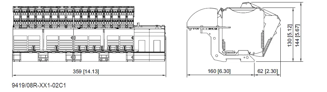
Accessories
 | Transmission of diagnostic data for up to eight segments via FF H1 | 207903
|
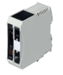
Fieldbus power supply
 | Fieldbus supply, diagnostics and adjustable warning level | 200588 |
Spring clamp clip
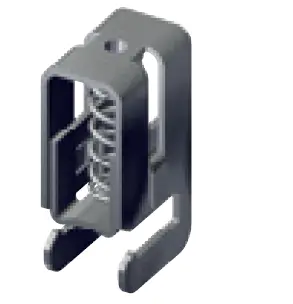 | Spring clamp clip KLBÜ C01 | 113509 |
We reserve the right to make alterations to the technical data, dimensions, weights, designs and products available without notice. The illustrations cannot be considered binding.
STAHL, INC.
13259 N. Promenade Blvd.
Stafford, TX 77477
Tel. +1 800 782 4357
Email US: [email protected]
Email CAN: [email protected]
rstahl.com


