MOXA MGate 4101-MB-PBS Series Field Bus Gateways
Technical Support Contact Information: www.moxa.com/support
Overview
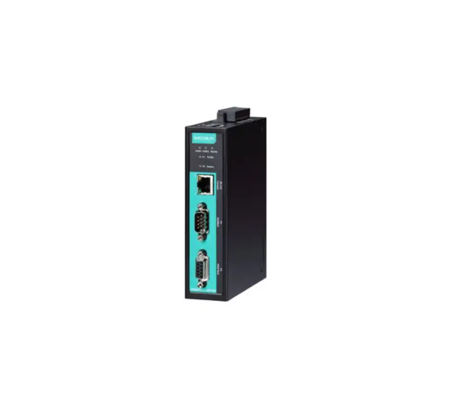
The MGateTM 4101-MB-PBS and 4101I-MB-PBS are 1-port Modbus serial to PROFIBUS slave gateways that provide protocol conversion for users who need to connect Modbus devices to Siemens PLCs.
Package Checklist
Before installing the MGate 4101-MB-PBS or 4101I-MB-PBS, verify that the package contains the following items:
- 1 MGate 4101-MB-PBS or 4101I-MB-PBS Modbus to PROFIBUS slave gateway
- RJ45 to DB9 cable (for use with the console)
- Quick installation guide (printed)
- Warranty Card
Please notify your sales representative if any of the above items are missing or damaged.
Optional Accessories
- WK-36-02: Wall mounting kit
- Mini DB9F-to-TB Adaptor: DB9 female to terminal block adapter
NOTE: This product is intended to be supplied by a Listed Power Adapter or DC power source marked “L.P.S.” (or “Limited Power Source”), rated 12 to 48 VDC, 275 mA minimum, Tma = 75°C minimum.
If need further assistance, please contact MOXA Inc. for further information.
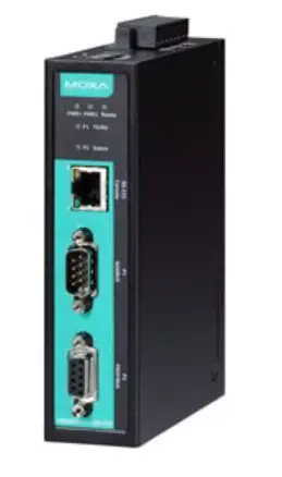
Hardware Introduction
LED Indicators
| LED | Color | Function |
| PWR1 | Green | Power is on |
| Off | Power is off | |
| PWR2 | Green | Power is on |
| Off | Power is off | |
| Ready | Green | Gateway is operational |
| Red | Check Configuration failed or Set Parameter failed | |
| Off | Power is off or fault condition exists | |
| P1 TX/RX (Modbus Serial) | Green | Serial device is transmitting data |
| Orange | Serial device is receiving data | |
| Off | No data is flowing to or from the serial port | |
| P2 Status (PROFIBUS) | Green | Steady: Data is exchanging |
| Red | Steady: Baudrate automatically identified. Wrong Slave Address or CHK_PRM or CHK_CFG will keep in steady red. | |
| Off | PROFIBUS offline |
The MGate 4101-MB-PBS and 4101I-MB-PBS both come with an RJ45 to DB9 cable for connecting to a serial console.
The reset button is used to load factory defaults. Use a pointed object such as a straightened paper clip to hold the reset button down for five seconds. Release the reset button when the Ready LED stops blinking.
Pull-high, Pull-low, and Terminator for RS-485
Remove the MGate 4101-MB-PBS’s top cover to adjust the DIP switches for each serial port’s pull-high resistor, pull-low resistor, and terminator.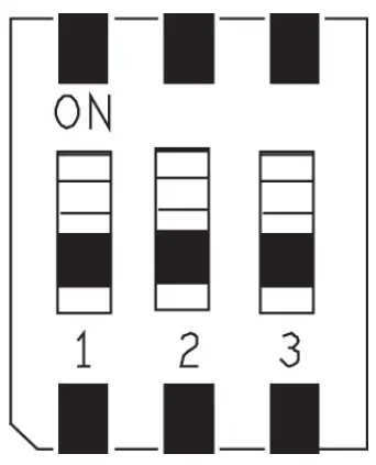
| SW | 1 | 2 | 3 |
| Pull-high resistor | Pull-low resistor | Terminator | |
| ON | 1 kilo-ohm | 1 kilo-ohm | 120 ohms |
| OFF | 150 kilo-ohms* | 150 kilo-ohms* | –* |
*Default
Hardware Installation Procedure
STEP 1:
Connect the power adapter. Make sure that the adapter is connected to an earthed socket. Connect the 12 to 48 VDC power line with the MGate 4101-MB-PBS/4101I-MB-PBS series’ terminal block, or connect the DIN rail power supply with the MGate 4101-MB-PBS/4101I-MB-PBS device’s terminal block.
STEP 2:
Use a PROFIBUS cable to connect the unit to a PROFIBUS PLC or other PROFIBUS master.
STEP 3:
Connect your device to the unit’s serial port.
STEP 4:
Attach the device to a DIN rail or the wall. The MGate 4101-MB-PBS/4101I-MB-PBS series is designed to be attached to a DIN rail or mounted on a wall. For DIN rail mounting, push down the spring and properly attach it to the DIN rail until it snaps into place. For wall mounting, install the wall mount kit (optional) first, and then screw the device onto the wall.
Wall or Cabinet Mounting
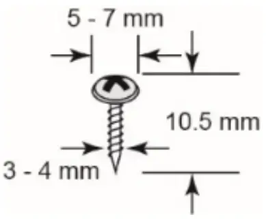
Mounting the MGate 4101-MB-PBS on to a wall requires two screws. The heads of the screws should be 5 to 7 mm in diameter, the shafts should be 3 to 4 mm in diameter, and the length of the screws should be more than 10.5 mm.
The following figure illustrates the two mounting options:
Software Installation Information
To install MGate Manager, please download it from Moxa’s website at http://www.moxa.com. Then, click the Installation button and follow the onscreen instructions. For more detailed information about MGate Manager, please refer to the User’s Manual.
Pin Assignments
Modbus Serial Port (Male DB9)
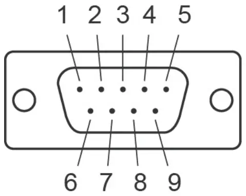
Pin | RS-232 | RS-422/RS-485 (4W) | RS-485 (2W) |
| 1 | DCD | TxD-(A) | – |
2 | RXD | TxD+(B) | – |
| 3 | TXD | RxD+(B) | Data+(B) |
4 | DTR | RxD-(A) | Data-(A) |
| 5 | GND | GND | GND |
6 | DSR | – | – |
| 7 | RTS | – | – |
8 | CTS | – | – |
| 9 | – | – | – |
PROFIBUS Serial Port (Female DB9)
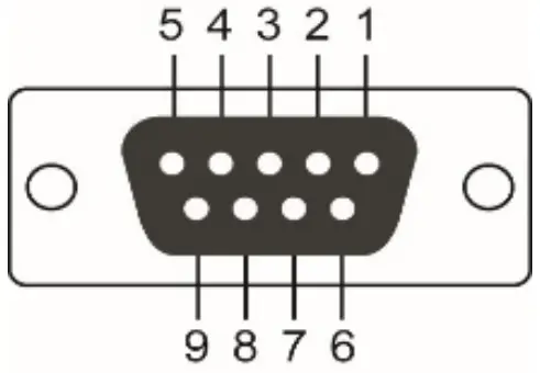
PIN | Signal Name |
| 1 | – |
2 | – |
| 3 | PROFIBUS D+ |
4 | RTS |
| 5 | Signal common |
6 | 5V |
| 7 | – |
8 | PROFIBUS D- |
| 9 | – |
Power Input and Relay Output Pinouts
 | V2+ | V2- |  | V1+ | V1- | ||
| Shielded Ground | DC Power Input 2 | DC Power Input 2 | N.O. | Common | N.C. | DC Power Input 1 | DC Power Input 1 |
Specifications
| Power Requirements | |
| Power Input | 12 to 48 VDC |
| Power Consumption | 275 mA (max.) |
| Operating Temperature | Standard Model: 0 to 60°C (32 to 140°F) Wide Temp. Model: – 40 to 75°C (-40 to 167°F) |
| Operating Humidity | 5 to 95% RH |
| Dimensions | 36 x 105 x 140 mm (1.42 x 4.13 x 5.51 in) |
| Reliability | |
| Alert Tools | Built-in buzzer |
| MTBF | MGate 4101-MB-PBS Series: 1,537,948 hrs. MGate 4101I-MB-PBS Series: 1,315,666 hrs. |

- ATEX Certificate No.: DEMKO 14 ATEX 1311X
- Protection Method: Ex nA nC IIC T4 Gc
- IECEx Certificate No: IECEx UL 14.0065X
- Standards: EN 60079-0:2012+A11:2013; EN 60079-15:2010; IEC 60079-0 Ed.6; IEC 60079-15 Ed.4.
- Conditions of safe usage:
• This equipment shall only be used in an area of not more than pollution degree 2, as defined in IEC/EN 60664-1.
• This equipment shall be installed in an enclosure that provides a degree of protection not less than IP54 in accordance with IEC/EN 60079-15. The enclosure should only be accessible by using a tool (wrench, screw driver, etc.).
• Transient protection shall be provided that is set at a level not exceeding 140% of the peak rated voltage value at the equipment’s power supply terminals. - Ambient Temperature: -40°C Tamb 75°C for MGate 4101X-MB-PBS-T models; 0°C Tamb 60°C for MGate 4101X-MB-PBS models.
Terminal Block Torque Value and Wire Gauge:
• Terminal block (the plug matched socket): rated at 300 V, 15 A, 105°C, 12-28 AWG (0.0804 mm2 to 3.31 mm2) wire size, torque value 4.5 lb-in (0.509 N-m). The input terminal cable size: 14 AWG (2.1 mm²).
ATTENTION
These devices are open-type devices that need be installed in an enclosure only accessible with the use of a tool, suitable for the environment.
NOTE: This equipment is suitable for use in Class I, Division 2, Groups A, B, C, and D or nonhazardous locations only.”
WARNING
EXPLOSION HAZARD–Do not disconnect equipment unless power has been switched off or the area is known to be non-hazardous.
WARNING
EXPLOSION HAZARD–Substitution of any components may impair suitability for Class I, Division 2.
Moxa Inc.
No. 1111, Heping Rd., Bade Dist., Taoyuan City 334004, Taiwan