STAHL 133248 Ex e Junction Boxes
Installation Equipment
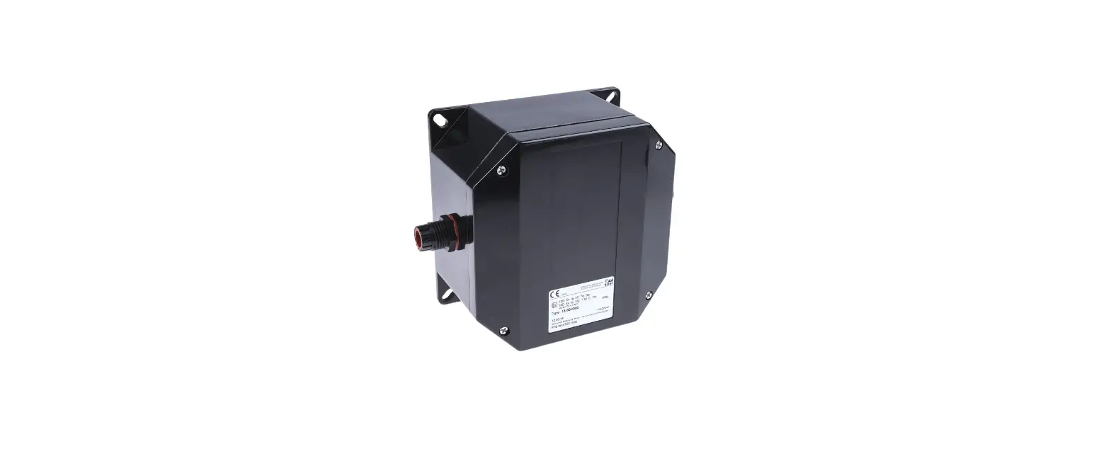
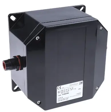
Ex e junction box
- Resistant Ex e enclosure, universally usable as connection or junction boxes and/ or to safeguard electric distributors up to 6.3 A
- IP66 degree of protection
- With mantle terminals or with a combination of mantle terminals and miniature fuses (optional)
WebCode 8118A
R. STAHL Series 8118 junction boxes are equipped with 4, 5 or 8 mantle terminals depending on their design size. As an option, miniature fuses can still be installed in addition. Junction boxes are therefore also suitable for safeguarding. The robust enclosure made from glass fibre reinforced polyester resin can be equipped with plastic or metal cable glands.
Technical Data
| Explosion Protection | |
| Scope of validity | European Union (ATEX) IECEx |
| Application range (zones) | 1 2 21 22 |
| IECEx gas certificate | IECEx PTB 06.0026 |
| IECEx gas explosion protection | Ex eb IIC T6 … T5 Gb |
| IECEx dust certificate | IECEx PTB 06.0026 |
| IECEx dust explosion protection | Ex tb IIIC T80 °C / T95 °C Db |
| ATEX gas certificate | PTB 99 ATEX 3103 |
| ATEX gas explosion protection | E II 2 G Ex eb IIC T6 … T5 Gb |
| ATEX dust certificate | PTB 99 ATEX 3103 |
| ATEX dust explosion protection | E II 2 D Ex tb IIIC T80 °C / T95 °C Db |
| Certificates | ATEX (PTB), Brazil (ULB), China (NEPSI), EAC (ENDCE), IECEx (PTB), Korea (KGS) |
| Ship approval | BVIS |
| Explosion protection note | For product label, see skope of validity. |
| Electrical Data | |
| Permissible rated operational current with 5 loaded terminals | for conductor cross-section 1.5 mm²: 13 A for conductor cross-section 2.5 mm²: 18 A for conductor cross-section 4 mm²: 24 A |
| Permissible rated operational current with 4 loaded terminals | for conductor cross-section 1.5 mm²: 15 A for conductor cross-section 2.5 mm²: 19 A for conductor cross-section 4 mm²: 25 A |
| Permissible rated operational current with ≤ 3 loaded terminals | for conductor cross-section 1.5 mm²: 16 A for conductor cross-section 2.5 mm²: 20 A for conductor cross-section 4 mm²: 25 A |
| Ambient Conditions | |
| Ambient temperature | -60 °C … +40 °C (T6) -60 °C … +55 °C (T5) |
| Ambient temperature | -76°F … +104°F (T6) -76°F … +131°F (T5) |
| Mechanical Data | |
| IP degree of protection (IEC 60529) | IP66 |
| Enclosure material | Polyester resin, Glass fibre reinforced |
| Enclosure colour | Dark grey |
| Flammability according to | IEC/EN 60695 UL 94 ASTM D635 |
| Silicone-free | No |
| Connection cross-section | 4 mm² |
| Permissible number of conductors per clamping unit, solid | mantle terminal M7 x 0.75 conductor cross-section 1.5 mm²: number of conductors min. 2, max. 4 conductor cross-section 2.5 mm²: number of conductors min. 2, max. 2 |
| Permissible number of conductors per clamping unit, finely stranded prepared, core end sleeve crimped | mantle terminal M7 x 0.75 conductor cross-section 1.5 mm²: number of conductors min. 2, max. 3 conductor cross-section 2.5 mm²: number of conductors min. 2, max. 2 |
| Permissible number of conductors per clamping unit, finely stranded unprepared | mantle terminal M7 x 0.75 conductor cross-section 1.5 mm²: number of conductors min. 2, max. 3 conductor cross-section 2.5 mm²: number of conductors min. 2, max. 2 |
| Permissible number of conductors per clamping unit note | All conductors of a terminal must have identical cross sections and identical material. |
| Cover | Screw-on cover |
| Cover fixing type | M4 stainless steel screws, With captive screws |
| Width | 85 mm |
| Width, inches | 3.35 in |
| Height | 85 mm |
| Height, inches | 3.35 in |
| Depth | 55 mm |
| Depth, inches | 2.17 in |
| Packaging unit | 1 |
| Weight | 0.3 kg |
| Weight | 0.66 lb |
| Mounting / Installation | |
| Tightening torque of cover screw 1 | 1.4 Nm |
| Cover screw 1 tightening torque lbf in | 12.4 lbf in |
| Components | |
| Entry 1 | 3 x 8161/7-M20-1304-LT (Provided separately) |
| Entry 1 type | Polyamide cable gland, black |
| Entry 1 | M20 x 1.5 |
| Entry 1 terminal area | 4 – 13 mm |
| Entry 1 clamping range, inch | 0.16 – 0.51 in |
| Metal entry possible 1 | No |
| Components | |
| Entry 2 | 1 x 8290/3-M20 (Provided separately) |
| Entry 2 type | Polyamide stopping plug |
| Entry 2 | M20 x 1.5 |
| Metal entry possible 2 | No |
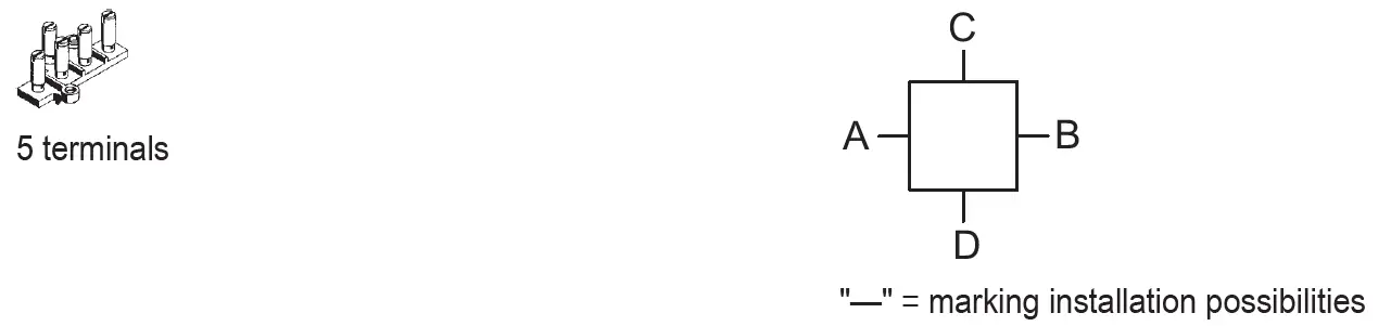
| Entries installation options/side | Size 1: 4x M20 (A+B+C+D) |
| Type of terminals 1 | 5 x Mantle terminal 4 mm² |
Technical Drawings – Subject to Alterations
Dimensional Drawings (All Dimensions in mm [inches]) – Subject to Alterations
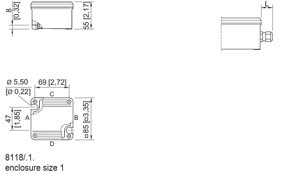
- Length L
- protrusion length for cable glands, Series 8161
- in case of M20: 25 … 31 [0.98 … 1.22]
- in case of M25: 27 … 33 [1.06 … 1.3]
- in case of M32: 32 … 39 [1.26 … 1.54]
- protrusion length for cable glands with strain relief, Series HSK-K-MZ
- in case of M25: 41 [1,61]
Accessories
| Cable gland made of | plastic | Art. No. |
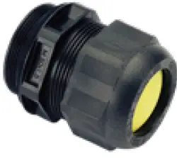 | 8161/7-M20-1307-LT, Ex e Plastic, M20 x 1.5, cable outer diameter 7 to 13 mm Lot size 50 pieces | 239204 |
Stopping plug
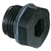 | 8290/3-M20 Plastic, M20 x 1.5 Lot size 100 pieces | 285773 |
Brass plate with thread
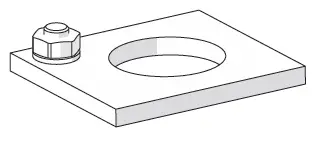 | 8118 size 1, plate 37 x 30 mm [1.46 x 1.18″] 1 x M20 x 1.5 with M4 PE connection (left) for installation in enclosure size 1, size 2 and size 3 | 168913 |
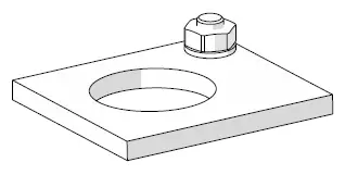 | 8118 size 1, plate 37 x 30 mm [1.46 x 1.18″] 1 x M20 x 1.5 with M4 PE connection (right) for installation in enclosure size 1, size 2 and size 3 | 168914 |
We reserve the right to make alterations to the technical data, dimensions, weights, designs and products available without notice. The illustrations cannot be considered binding2022-11-25 R. STAHL Schaltgeräte GmbH | Am Bahnhof 30 | 74638 WALDENBURG 4/4 Tel. +49 7942 943 1700 | +49 7942 943 1777 | Email: [email protected] | r-stahl.com


