ELATION 1960 Proteus Rayzor
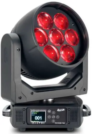
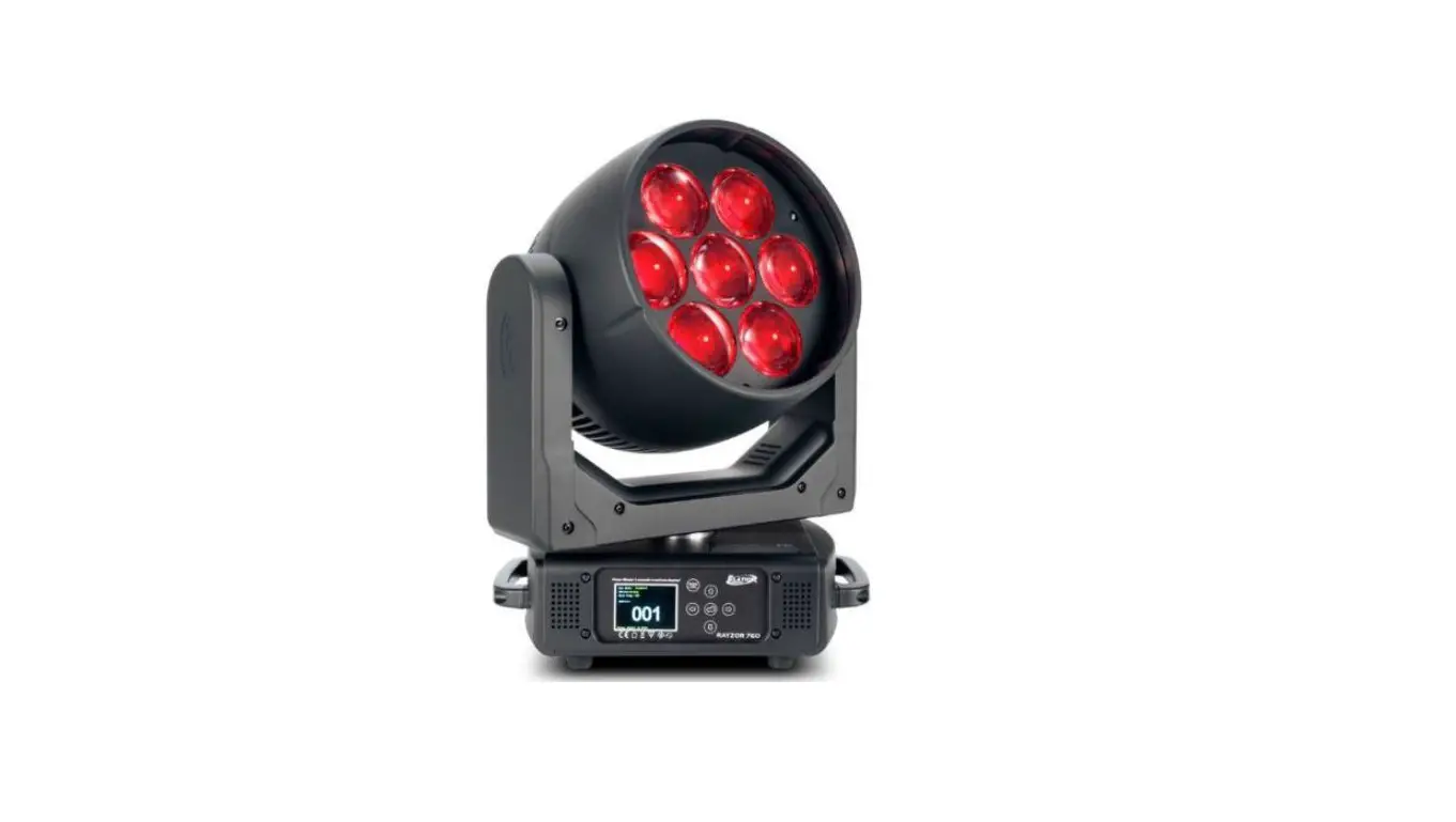
The PROTEUS RAYZOR 1960 is a lighting fixture manufactured by ELATION PROFESSIONAL. It comes with 25/100/176 DMX channels and has various features such as RGBW Pixel FX Table, Spark LED FX Table, and Waveforms. It is intended for use by trained personnel only and is not suitable for private use.
Product Usage Instructions
- Read and understand the instructions in this manual carefully and thoroughly before attempting to operate this device.
- Make sure the fixture is properly grounded as it falls under protection class 1.
- Do not attempt any repairs yourself as there are no user-serviceable parts inside the unit. Doing so will void your manufacturer’s warranty.
- Install the fixture following the guidelines mentioned in the Installation section of the manual.
- Use the Control Panel to control and adjust the settings of the fixture.
- Refer to the Lighting Console Patching Guidelines section for information on how to patch the fixture with a lighting console.
- Refer to the DMX Traits section for information on how to program the fixture using DMX.
- Refer to the FX Generator Guidelines section for information on how to create effects using the fixture.
- Refer to the System Menu section for information on how to access and adjust the system settings of the fixture.
- Refer to the Error Codes section if you encounter any issues with the fixture.
INTRODUCTION
Please read and understand the instructions in this manual carefully and thoroughly before attempting to operate this device. These instructions contain important safety and use information. This device is intended for use by trained personnel only, and is not suitable for private use.
UNPACKING
Every device has been thoroughly tested and has been shipped in perfect operating condition. Carefully check the shipping carton for damage that may have occurred during shipping. If the carton is damaged, carefully inspect the device for damage, and be sure all accessories necessary to install and operate the device have arrived intact. In the event that damage has been found or parts are missing, please contact our customer support team for further instructions. Please do not return this device to your dealer without first contacting customer support. Please do not discard the shipping carton in the trash. Please recycle whenever possible.
IP65 RATED
An IP rated lighting fixture is commonly installed in outdoor environments and has been designed with an enclosure that effectively protects the ingress (entry) of external foreign objects such as dust and water. The International Protection (IP) rating system is commonly expressed as “IP” followed by two numbers (i.e. IP65) where the numbers define the degree of protection. The first digit (Foreign Bodies Protection) indicates the extent of protection against particles entering the fixture, while the second digit (Water Protection) indicates the extent of protection against water entering the fixture. An IP65 rated lighting fixture, such as this one, has been designed and tested to protect against the ingress of dust (6) and low-pressure water jets from any direction (5).
BOX CONTENTS
Power Cable (x1)
CUSTOMER SUPPORT
Contact ELATION Service for any product-related service and support needs. Also visit forums.elationlighting.com with questions, comments or suggestions.
ELATION SERVICE USA – Monday – Friday 8:00am to 4:30pm PST
323-582-3322 | Fax 323-832-9142 | [email protected]
ELATION SERVICE EUROPE – Monday – Friday 08:30 to 17:00 CET
+31 45 546 85 63 | Fax +31 45 546 85 96 | [email protected]
REPLACEMENT PARTS – please visit parts.elationlighting.com
LENS POSITION FOR SHIPPING AND PACKAGING:
When re-packaging this fixture for shipping or transportation, the device must be placed securely into the form-fitting foam in-lay (FIL) that was included in the box when the fixture was first purchased. Please refer to the Dimensional Drawings section of this manual for detailed information about the foam in-lay. Additionally, it is CRITICALLY IMPORTANT to orient the head of the fixture so that the lens is pointing toward the base of the unit, as illustrated below. Failure to do so can result in damage to the fixture’s zoom function while in transit. Reminder notices will be stamped into the foam in-lay itself as a precautionary measure.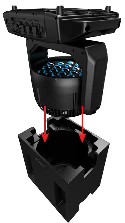
WARR ANTY RETURNS (USA ONLY)
To obtain warranty service, a Return Materials Authorization (RMA) number must first be obtained from ELATION. It is the Customer’s responsibility to provide product proof of purchase and serial number by acceptable evidence such as an invoice copy or an approved ELATION Extended Warranty Certificate (“EWC”) and any relevant maintenance records at the time warranty service is sought. Failure to provide acceptable evidence of product proof of purchase or EWC and any relevant maintenance records may be cause for denial of warranty service.
Products returned for warranty service must be sent without any accessories (i.e., power, data, and safety cables, brackets, clamps, rigging hardware, frost filters, gel frames, barn doors, lens, hoses, nozzles, rack mounting hardware, etc.), must be boxed using the original and/or suitable packaging materials (double-box and foam) that provides ample product pro-tection for ground and/or air freight transit, and must be shipped freight pre-paid and insured to ELATION in Los Angeles, CA or an ELATION Authorized Service Center. The RMA number must be clearly written on the outside of the return box, and a brief description of the prob-lem and the RMA number must be documented and included in the box.
Products returned for warranty service without an RMA number clearly marked on the out-side of the package will be refused and returned to the shipper at the Customer’s expense. Products returned for warranty service, which are received damaged due to inadequate and/or improper packaging and/or due to damage caused by shipping carrier, may incur addi-tional repair charges before warranty service begins and/or may void this warranty. If any product accessories (included and/or optional) are shipped with the product, ELATION and/or the ELATION Authorized Service Center shall have no liability what so ever for the loss and/or damage to any such accessories, nor the safe return thereof. If the requested war-ranty repairs or service (including parts replacement) are within the terms of this warranty, ELATION will pay return ground transportation shipping charges to a single designated point within the United States.
SAFETY PRECAUTIONS
This fixture is a sophisticated piece of electronic equipment. To guarantee a smooth opera-tion, it is important to follow all instructions and guidelines in this manual. Elation Profes-sional is not responsible for injuries and/or damages resulting from the misuse of this fixture due to the disregard of the information printed in this manual. Only qualified and/or certified personnel should perform installation of this fixture and only the original rigging parts in-cluded with this fixture should be used for installation. Any modifications to the fixture and/or the included mounting hardware will void the original manufacturer’s warranty and in-crease the risk of damage and/or personal injury.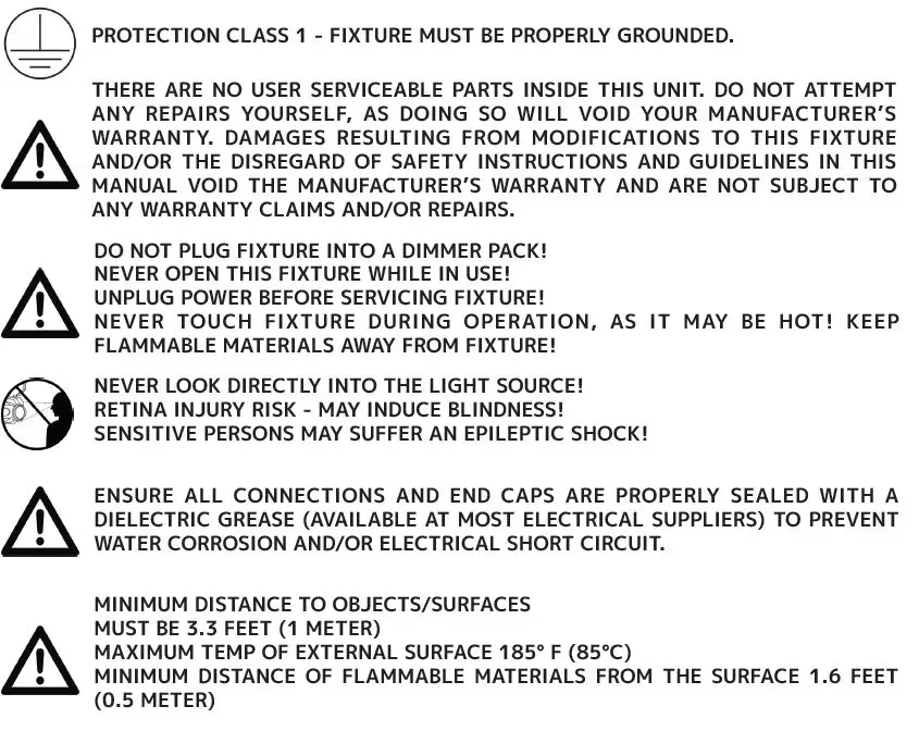
- DO NOT TOUCH the fixture housing during operation. Turn OFF the power and allow ap-proximately 15 minutes for the fixture to cool down before servicing.
- DO NOT shake fixture, and avoid using brute force when installing and/or operating the fixture.
- DO NOT operate the fixture if the power cord is frayed, crimped, damaged, and/or if any of the power cord connectors are damaged and do not plug into the fixture securely with ease.
- NEVER force a power cord connector into the fixture. If the power cord or any of its con-nectors are damaged, replace it immediately with a new one of the same power rating.
- DO NOT block any air ventilation slots.
- All fan and air inlets must remain clean and never blocked.
- Leave approx. 6” (15cm) between the fixture and other devices or a wall in order to allow for proper cooling.
- Always disconnect the fixture from the main power source before performing any type of service and/or cleaning procedure.
- Only handle the power cord by the plug end. Never pull out the plug by tugging on the wire portion of the cord.
- During the initial operation of this fixture, a light smoke or smell may emit from the inte-rior of the fixture. This is a normal process and is caused by excess paint in the interior of the casing burning off from the heat associated with the lamp. This will decrease gradually over time.
- Consistent operational breaks will ensure fixture will function properly for many years.
- ONLY use the original packaging and materials to transport the fixture for service.
MAINTENANCE GUIDELINES
DISCONNECT POWER BEFORE PERFORMING ANY MAINTENANCE!
CLEANING
Frequent cleaning is recommended to ensure proper function, optimized light output, and an extended life. The frequency of cleaning depends on the environment in which the fixture operates: damp, smoky or particularly dirty environments can cause greater accumulation of dirt on the fixture’s optics. Periodically clean the external lens surface with a soft cloth to avoid dirt/debris accumulation. NEVER use alcohol, solvents, or ammonia-based cleaners.
MAINTENANCE
Regular inspections are recommended to insure proper function and extended life. There are no user serviceable parts inside this fixture. Please refer all other service issues to an autho-rized Elation service technician. Should you need any spare parts, please order genuine parts from your local Elation dealer.
Please refer to the following points during routine inspections:
- A detailed electric check by an approved electrical engineer every three months, to make sure the circuit contacts are in good condition and prevent overheating.
- Be sure all screws and fasteners are securely tightened at all times. Loose screws may fall out during normal operation, resulting in damage or injury as larger parts could fall.
- Check for any deformations on the housing, color lenses, rigging hardware, and rigging points (ceiling, suspension, trussing). Deformations in the housing could allow for dust to enter into the fixture. Damaged rigging points or unsecured rigging could cause the fixture to fall and seriously injure a person(s).
- Electric power supply cables must not show any damage, material fatigue or sediments. NEVER remove the ground prong from the power cable.
FIXTURE DISASSEMBLY
The following points should be observed after performing any maintenance procedure that requires disassembly of the unit:
- After the unit has been reassembled, open the valve and allow the unit to run for approxi-mately 2 hours in order to dry out any moisture that has been trapped inside the fixture. The process should continue until indicated humidity drops below 15% for the head and 30% for the base.
- Once this has been achieved, the light can be switched off, but the unit should remain connected to power so that the cooling fan can cool down the unit. Please note that al-lowing cool down time should ALWAYS be done after lamp operation.
- Some units may require partial disassembly in order to gain access to the valve. Please contact Elation service for information regarding the location and access procedure for the valve on your specific unit model.
BATTERY REPLACEMENT
Installing the battery in the incorrect orientation will lead to internal electron-ics and battery damage. A qualified electrician should be used for all electrical connections and/or installations.
Follow the directions below to replace the battery:
- Loosen the screw cap for the battery compartment, as shown below to the left.
- Remove old battery and replace. Make sure the battery is oriented with the negative “-” terminal towards the inside and the positive “+” terminal towards the outside. Refer to the illustration below to the right.
- Replace and tighten screw cap to secure the battery in place.

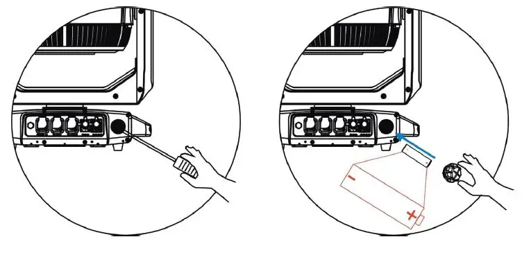
NOTE: Replace the battery only with an Li-ion battery (IRC14500/700mAh), which can be ordered from the Elation Parts Website. https://parts.elationlighting.com/catalog/product/view/id/18373/s/60420050026/cat-egory/2/
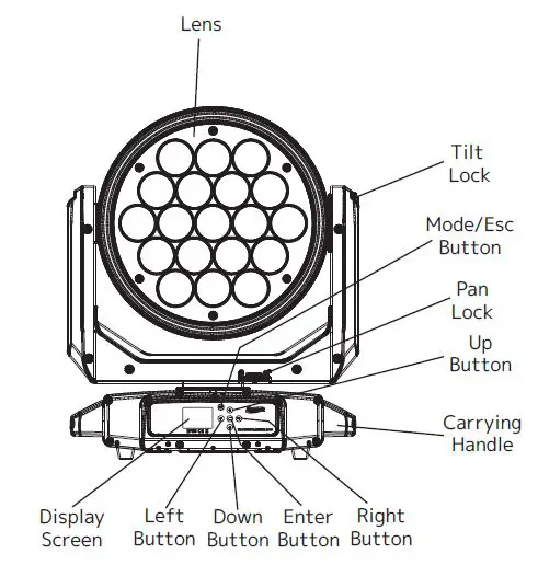
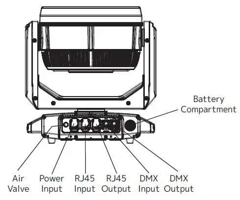
OVERVIEW
INSTALLATION
- FLAMMABLE MATERIAL WARNING
Keep fixture minimum 5.0 feet (1.5m) away from flammable materials and/or pyro-technics. - ELECTRICAL CONNECTIONS
A qualified electrician should be used for all electrical connections and/or installa-tions. - MINIMUM DISTANCE TO SURFACES/OBJECTS IS 3.3 FEET (1 METER).
- MINIMUM DISTANCE TO FLAMMABLE MATERIALS IS 1.6 FEET (0.5 METER). EXTERNAL SURFACE CAN REACH TEMPERATURES OF 185° F (85° C).
- DO NOT INSTALL THE FIXTURE IF YOU ARE NOT QUALIFIED TO DO SO!
- Fixture MUST be installed following all local, national, and country commercial electrical and construction codes and regulations.
- Before rigging/mounting a single fixture or multiple fixtures to any metal truss/structure or placing the fixture(s) on any surface, a professional equipment installer MUST be consulted to determine if the metal truss/structure or surface is properly certified to safely hold the com-bined weight of the fixture(s), clamps, cables, and accessories.
- Overhead rigging requires extensive experience, including calculating working load limits, installation material being used, and periodic safety inspection of all installation material and the fixture, among other skills. If you lack these qualifications, do not attempt the installa-tion yourself. Improper installation can result in bodily injury.
- Fixture ambient operating temperature range is -4° to 113°F (-20° to 45°C). Do not operate the fixture when the ambient temperature falls outside of this range.
- Fixture(s) should be installed away from walking paths, seating areas, or areas were unauthor-ized personnel might reach the fixture by hand.
- NEVER stand directly below the fixture(s) when rigging, removing, or servicing.
- Overhead fixture installation must always be secured with a secondary safety attachment, such as an appropriately rated safety cable.
- Allow approximately 15 minutes for the fixture to cool down before serving.
INSTALL ATION GUIDELINES
OMEGA BRACKET INSTALLATION
When mounting the fixture to a truss using Omega brackets, first attach a mounting clamp to each Omega bracket using an M10 screw inserted through the center hole of each Omega bracket (see top illustration). Then, insert the Omega Brackets into the outer mounting holes on the underside of the fixture (see lower illustation). Secure the Omega Brackets to the fix-ture by turning each quick-lock fastener ¼ turn clockwise. Always check to make sure that each fastener is completely locked.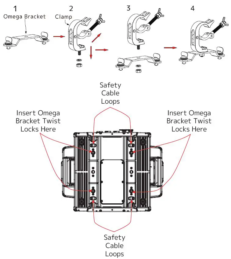
SAFETY CABLE: ALWAYS ATTACH A SAFETY CABLE WHENEVER INSTALLING THIS FIXTURE IN A SUSPENDED ENVIRONMENT TO ENSURE THAT THE FIXTURE WILL NOT FALL IF THE CLAMP FAILS. ONLY USE DESIGNATED RIGGING POINTS FOR SAFETY CABLE, AND NEVER ATTACH A SAFELY CABLE TO A CARRYING HANDLE.
CLAMP INSTALLATION
Alternately, the fixture can be mounted to a truss using mounting clamps secured directly to the fixture itself. Insert one minimum grade 8.8 steel M12x25mm bolts (not included) into the mounting hole of each mounting clamp. Please note that TWO (2) MOUNTING CLAMPS are required to support the fixture safely and securely. Thread each bolt into the match-ing 12M holes on the underside of the fixture, as shown in the illustration below. Both bolt must be threaded to a depth of at least 18mm (0.7in) into the fixture base.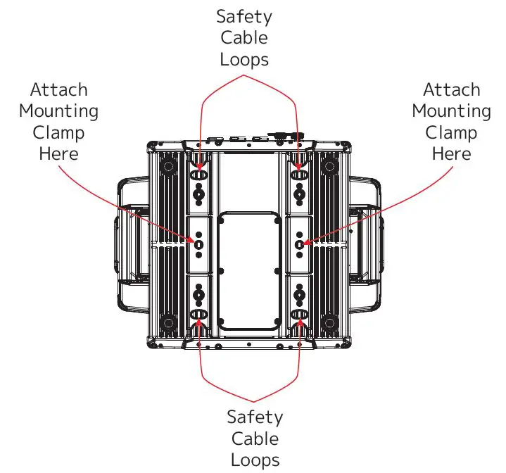
SAFETY CABLE: ALWAYS ATTACH A SAFETY CABLE WHENEVER INSTALLING THIS FIXTURE IN A SUSPENDED ENVIRONMENT TO ENSURE THAT THE FIXTURE WILL NOT FALL IF THE CLAMP FAILS. ONLY USE DESIGNATED RIGGING POINTS FOR SAFETY CABLE, AND NEVER ATTACH A SAFELY CABLE TO A CARRY-ING HANDLE.
RIGGING
Overhead rigging requires extensive experience, including calculating working load limits, installation material being used, and periodic safety inspection of all installation material and the fixture, among other skills. If you lack these qualifications, do not attempt the installation yourself. Improper installation can result in bodily injury. The fixture is fully operational in the following positions: hanging from a horizontal truss, suspended sideways from a vertical truss, or standing upright on a flat, level surface. See the illustration below for reference.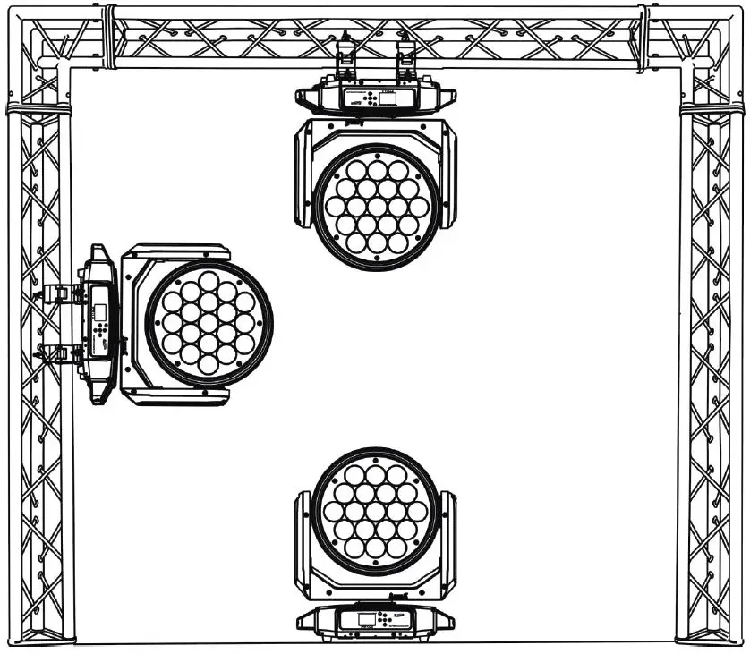
ART-NET AND sACN CONNECTION
When connecting the fixture to a network switch to control multiple devices, a Gigabit Ethernet Switch that supports IGMP (Internet Group Management Protocol) is required. Using a Gigabit Ethernet Switch that does not support IGMP can cause erratic behavior of all connected devices to the switch. Visit the link below for more information about IGMP. https://en.wikipedia.org/wiki/Internet_Group_Management_Protocol
POWER AND DATA CABLES
TO MAINTAIN THE IP65 RATING INTEGRITY OF THE FIXTURE, ALL CABLES MUST BE RUN TOWARDS THE GROUND IN ORDER TO PREVENT WATER ACCUMULATION AROUND THE CONNECTIONS.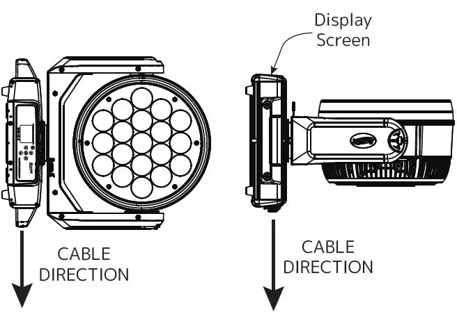
- RJ45 DATA CABLES
THE INCLUDED RJ45 DATA CABLE IS FOR FIXTURE TO FIXTURE INTERCONNECTIONS ONLY! THE RJ45 CABLE CONNECTORS MAY NOT BE COMPATIBLE WITH OTHER RJ45 OR ETHERNET TYPE CONNECTORS. - POWER AND DATA CONNECTIONS
- ENSURE ALL CONNECTIONS AND END CAPS ARE PROPERLY SEALED WITH A DIELECTRIC GREASE (AVAILABLE AT MOST ELECTRICAL SUPPLIERS) IN ORDER TO PREVENT WATER CORROSION AND/OR ELECTRICAL SHORT CIRCUIT.
- TO MAINTAIN IP65 RATING INTEGRITY AND PREVENT WATER FROM ENTERING THE FIXTURE, SEAL ALL UNUSED CONNECTION RUBBER CAPS.
POTENTIAL INTERNAL FIXTURE DAMAGE FROM EXTERNAL SOURCES OF LIGHT BEAMS
External sources of light beams from direct sunlight, lighting and moving head fixtures, and lasers, which are focused directly towards the exterior housing and/or penetrate the front lens opening of Elation lighting fixtures, can cause severe internal damage including burning of optics, dichroic color filters, glass and metal gobos, prisms, animation wheels, frost filters, iris, shutters, motors, belts, wiring, discharge lamps, and LEDs.
This issue is not specific only to Elation lighting fixtures, but rather it is a common issue with lighting fixtures from all manufacturers. Although there is no true way to fully prevent this issue from happening, the guidelines below can reduce the risk of potential damage. Contact Elation Service for more details.
DO NOT EXPOSE THE FIXTURE AND/OR FRONT LENS OPENING TO LIGHT BEAMS FROM DIRECT SUNLIGHT, OTHER LIGHTING OR MOVING HEAD FIXTURES, AND LASERS DURING UNPACKING, INSTALLATION, USE, AND EXTENDED IDLE TIMES OUTDOORS. DO NOT FOCUS A LIGHT BEAM FROM ONE LIGHTING FIXTURE DIRECTLY TOWARDS ANOTHER.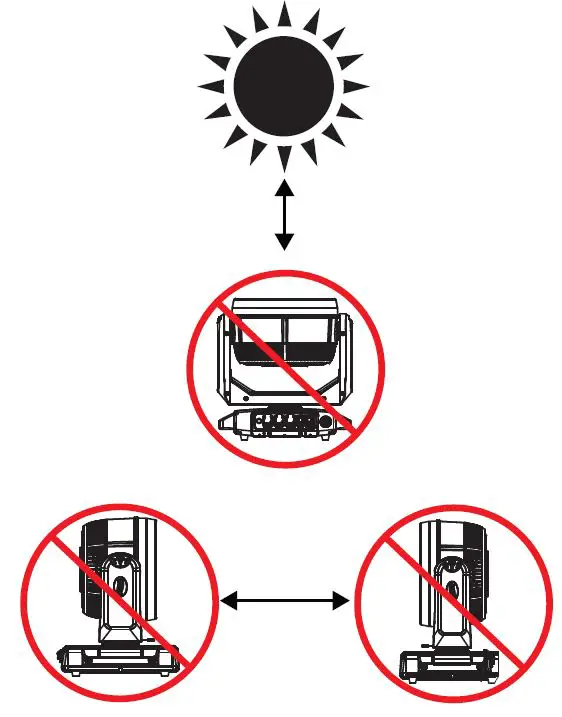
SUN PROTECTION MODE
This fixture incorporates an automatic protection from harmful sun rays, which can damage the fixture’s internal components as a result of extended exposure. The fixture uses an inter-nal sensor to determine physical orientation, then point the fixture towards the ground to prevent sunlight from entering the lens. Please note that this feature only works when the fixture is powered on. When performing installation or maintenance with the fixture powered off, it is important to always move the lenses out of direct sunlight and/or point them manually to the ground. Even a few minutes of sunlight exposure can cause damage to components inside the fixture. The Sun Protection setting is part of the “No DMX Status” menu, and can be accessed by navi-gating to PERSONALITY > STATUS SETTINGS > NO DMX STATUS > SUN PROTECTION. A quick reference is provided in the table below. Refer to the System Menu section of this manual for detailed information.
| MAIN MENU | SUB MENU | OPTIONS | |
| Personality | Status Settings | No DMX Status | Sun Protection (default) |
| Close | |||
| Hold | |||
| Auto Program | |||
The sun protection position is activated under the following conditions:
- Power on without DMX signal: The fixture always starts in sun protection mode.
- No DMX Status set to “Sun Protection” option: The fixture enters sun protection mode after approximately 3 minutes.
- Remote DMX control: The sun protection position can be temporarily activated from the lighting console without the need to create a custom position preset. The ability to cor-rectly orient the lens towards the ground is built into the fixture. Note that this also means some fixtures hanging straight down may not move their heads. Hold “Sun Protect Position” for 3s to set the fixture to the sun protection position.
The display screen should display the phrase “Sun Protection: Active” to confirm that this feature has been activated.
The sun protection position is deactivated under the following conditions:
- DMX signal is connected.
- Remote DMX control: Hold “Sun Protection Off” for 3s.
The sun protection position always uses a 5 second fade time when it is activated or deacti-vated to avoid harsh movements of the fixture.
HIBERNATION MODE
This mode disables motors and most electronics in order to reduce wear on the fixture’s inter-nal components. The user has the ability the define the period of time that the fixture can remain inactive before it enters hibernation mode. This feature can be accessed by navigating in the main menu to PERSONALITY > STATUS SETTINGS > HIBERNATION (see the System Menu section of this manual for detailed information). The default setting for hibernation delay time is 15 minutes, but it can be adjusted from 1 min to 99 min, or switched off completely.
Hibernation mode is activated under the following conditions:
- Loss of DMX signal: the fixture enters hibernation after the timeout expires. Default is 15 minutes.
- Remote DMX control: Press and hold “Hibernate Fixture” for 3s.
Hibernation mode is deactivated under the following conditions:
- DMX signal is connected.
- Remote DMX control: Hold “Hibernate Off” for 3s.
The fixture will perform a full calibration cycle, then assume the current DMX status. Please note that the Hibernation does not change the PT position of the fixtures. This allows the user to set the desired position and then issue the Hibernate command. To ensure the fixture is protected from harmful sunrays, it is recommended to either leave the “No DMX Status” in “Sun Protection” mode (so that the fixture is already in the correct posi-tion after 3 minutes of DMX loss) or set the fixture to a safe Pan Tilt position manually prior to putting the fixture in hibernation mode. Burn and heat damage to the fixture’s interior components due to external light sources (sun or other fixtures shining into the lens) is never covered under the manufacturer’s warranty.
TORQUE SETTINGS FOR SCREWS
PANEL SCREWS MUST BE TIGHTENED WITH A TORQUE WRENCH. REFER TO THE TABLE AND DIAGRAM BELOW FOR PROPER TORQUE SETTINGS.
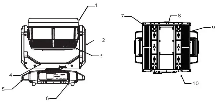
| ITEM NO. | DESCRIPTION | TORQUE SETTING |
| 1 | Upper Head Cover | 8.7 + 0.9 lb-in (10 + 1 kgf-cm) |
| 2 | Arm Cover | 8.7 + 0.9 lb-in (10 + 1 kgf-cm) |
| 3 | Lower Head Cover | 8.7 + 0.9 lb-in (10 + 1 kgf-cm) |
| 4 | Upper Arm Cover | 8.7 + 0.9 lb-in (10 + 1 kgf-cm) |
| 5 | Handle | 20.0 + 2.0 lb-in (23 + 2.3 kgf-cm) |
| 6 | Display Board | 8.7 + 0.9 lb-in (10 + 1 kgf-cm) |
| 7 | Machine Leg | 8.7 + 0.9 lb-in (10 + 1 kgf-cm) |
| 8 | Bottom Seal Plate | 5.2 + 0.5 lb-in (6 + 0.6 kgf-cm) |
| 9 | Quick Lock Base Holder | 8.7 + 0.9 lb-in (10 + 1 kgf-cm) |
| 10 | XLR Board | 8.7 + 0.9 lb-in (10 + 1 kgf-cm) |
CAUTION! DO NOT OVER TORQUE SCREWS AS THIS CAN CAUSE LEAKAGE ISSUES! TO CONFIRM THE IP65 INTEGRITY AFTER A LAMP REPLACEMENT, TEST THE FIXTURE USING THE IP TESTER. CONTACT ELATION SERVICE FOR MORE DETAILS.
CAUTION! THE USE OF PROTECTIVE GLOVES AND SAFETY GOGGLES IS STRONGLY RECOMMENDED WHILE PERFORMING THE IP PRESSURE TEST! AVOID PLACING YOUR FACE, EYES, HANDS, ETC IN CLOSE PROXIMITY TO THE FIXTURE’S LENS WHILE PERFORMING THE TEST!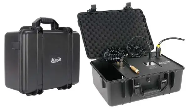
| IP PRESSURE TESTING PARAMETERS | |||
| Test Type | Minimum Pressure | Maximum Pressure | Steady/Hold Time |
| Vacuum Test | -4.35 psi (-30.00 KPa) | 5.08 psi (-35.00 KPa) | 10 sec |
| Pressure Test | 3.62 psi (25.00 KPa) | 4.35 psi (30.00 KPa) | 10 sec |
REMOTE DEVICE MANAGEMENT (RDM)
NOTE: In order for RDM to work properly, RDM enabled equipment must be used through-out the entire system, including DMX data splitters and wireless systems.
Remote Device Management (RDM) is a protocol that sits on top of the DMX512 data stan-dard for lighting, allowing the DMX systems of the fixtures to be modified and monitored remotely. This proto-col is ideal for instances in which a unit is installed in a location that is not easily accessible.
With RDM, the DMX512 system becomes bi-directional, allowing a compatible RDM enabled con-troller to send out a signal to devices on the wire, as well as allowing the fixture to respond (known as a GET command). The controller can then use its SET command to modify settings that would typically have to be changed or viewed directly via the unit’s display screen, including the DMX Address, DMX Channel Mode, and Temperature Sensors.
FIXTURE RDM INFORMATION:
| RDM Code | Device ID | Device Model ID | Personality ID |
| 0x61F | Open | 1567 | Open |
Please be aware that not all RDM devices support all RDM features, and therefore it is im-portant to check beforehand to ensure that the equipment that you are considering includes all of the fea-tures that you require.
The following parameters are accessible in RDM on this device:
- Sensor Definition
- Sensor Value
- Device Model Description
- Manufacturer Label
- Device Label
- DMX Personality
- DMX Personality Description
- Device Hours
- Pan Invert
- Tilt Invert
- Display Invert
CONTROL PANEL
This fixture features an easy to navigate system menu. The control panel located on the front of the fixture (see image below) provides access to the main system menu and is where all necessary system adjustments are made to the fixture. During normal operation, pressing the MODE/ESC button once will access the fixture’s main menu. Once in the main menu, you can navigate through the different functions and access the sub-menus with the UP, DOWN, RIGHT, and LEFT buttons. Once you reach a field that requires adjusting, press the ENTER button to select that field and use the UP and DOWN buttons to adjust the setting options for that field. Pressing the ENTER button once more will confirm your setting. You may exit the main menu at any time without making any adjustments by pressing the MODE/ESC button. To access the LCD Menu Control Display via the internal battery, press and hold the MODE/ESC button for 10 seconds. The LCD Menu Control Display will shut OFF automatically about 1 minute from the last button press.
BATTERY
This unit features a dedicated battery that can be used to power the screen display. This allows the user to configure the device’s channel mode, DMX address, or any other screen-accessible features without needing to power on the device or even connect it to a power source. To activate the display on battery power, press and hold the MODE button for 3 seconds.
| ELATION PROTEUS RAYZOR 1960 SYSTEM MENU | ||||
| Supports Software Versions: 2.0.0 | ||||
| Features subject to change without notice. Rotation direction (clockwise/counter-clockwise) and control of effects depend on head orientation and pan/tilt settings. Default settings listed in bold. | ||||
| MAIN MENU | SUB MENU | OPTIONS / VALUES | DESCRIPTION | |
| FUNCTION | Set DMX Address | A001 – Axxx | ||
| DMX Value | ALL… | Displays DMX value | ||
| Secondary Mode | Secondary1 | |||
| Secondary2 | ||||
| Secondary3 | ||||
| Auto Program | Primary | Auto Program | ||
| Alone | ||||
| INFORMATION | Time Information | Current Time | xxxx hours | Power On Running Time |
| Total Run Time | xxxx hours | Fixture running time | ||
| Last Run Time | xxxx hours | Run time since last reset | ||
| Clear Last Run Password = 038 | On / Off | Clear last run time | ||
| Temperature Info | LED Temperature | xxx °C / °F | ||
| Head Temperature | xxx °C / °F | |||
| Base Temperature | xxx °C / °F | |||
| Humidity Info | Head Humidity | xxx % | ||
| Base Humidity | xxx % | |||
| Ethernet IP | Ethernet IP xxx. xxx. xxx. xxx xxx. xxx. xxx. xxx | |||
| Fan Info | Head Fan 1 | xxxx RPM | ||
| … | … | |||
| Software Info | Vx.x.x | |||
| Error Info | Error Record 1 | Pan… | ||
| …. | … | |||
| Error Record 10 | Pan… | |||
| PERSONALITY | Status Settings | Address via DMX | On / Off | |
| No DMX Status | Close | Select operation mode when DMX signal is lost or inter- rupted | ||
| Hold | ||||
| Auto | ||||
| Pan Reverse | On / Off | |||
| Tilt Reserve | On / Off | |||
| Pan Degree | 630 / 540 | |||
| Tilt Degree | 630 / 270 | |||
| Pan Tilt Path | Shortest Path | |||
| Continue Path | ||||
| Zoom Speed | Fast / Normal | |||
| CONTINUED ON NEXT PAGE | ||||
| ELATION PROTEUS RAYZOR 1960 SYSTEM MENU | ||||
| MAIN MENU | SUB MENU | OPTIONS / VALUES | DESCRIPTION | |
| PERSONALITY (continued) | Status Settings (continued) | Feedback | On / Off | Movement Feedback |
| Hibernation | Off, 01min – 99min | Default = 15min | ||
| Service Setting | Password = 050 | |||
| Clear Err Info | On / Off | Clear Error Info | ||
| Fans Control | Auto | |||
| High | ||||
| Low | ||||
| Studio | ||||
| Mute | ||||
| Display Setting | Shutoff Time | 02min – 60min | Default = 05min | |
| Display Reverse | Off | Normal orientation | ||
| On | Inverted orientation | |||
| Auto | Automatically switch orienta- tion to keep display upright | |||
| Key Lock | On / Off | |||
| Temperature C/F | Celsius / Fahren | |||
| Initial Status | Pan = xxx | Initial effect position | ||
| … | ||||
| Select Signal | DMX Only | |||
| Art-Net | ||||
| sACN | ||||
| Klingnet | On / Off | |||
| Ethernet IP | xxx. xxx. xxx. xxx | |||
| Ether Mask IP | xxx. xxx. xxx. xxx | |||
| Set Universe | 000 – 32767 | Set Art-Net universe | ||
| DHCP | On / Off | ? | ||
| Dimmer Mode | Standard | |||
| Stage | ||||
| TV | ||||
| Architectural | ||||
| Theatre | ||||
| Stage2 | ||||
| Delay | 0s, 0.1s…10s | |||
| Refresh | 900Hz – 25KHz | Default = 1200Hz | ||
| Dimmer Curve | Linear | |||
| Square | ||||
| Inverse Square | ||||
| S-Curve | ||||
| Reset Def | On | Passcode = 050 | Restore to factory settings | |
| Off | ||||
| CONTINUED ON NEXT PAGE | ||||
| ELATION PROTEUS RAYZOR 1960 SYSTEM MENU | ||||
| MAIN MENU | SUB MENU | OPTIONS / VALUES | DESCRIPTION | |
| RESET FUNCTION | Reset All | |||
| Reset Pan & Tilt | ||||
| Reset Others | ||||
| EFFECT ADJUST | Test Channel | Pan… | ||
| Manual Control | Pan = xxx | Use for fine adjustment | ||
| … | ||||
| Calibration | Passcode = 050 | Pan = xxx | Calibrate and adjust effects | |
| … | ||||
| USER MODE SET | User Mode | Standard Mode | ||
| Pixels | ||||
| Extended Mode | ||||
| EDIT PROGRAM | Select Program | Auto Pro Part 1 = Program 1 – 10 | Default = Program 1 | |
| Auto Pro Part 2 = Program 1 – 10 | Default = Program 1 | |||
| Auto Pro Part 3 = Program 1 – 10 | Default = Program 1 | |||
| Edit Program | Prog 1 : Prog 10 | Prog Test | Testing Program | |
| Step 01 = SCxxx | Program In Loop | |||
| Step 64 = SCxxx | Save and Exit | |||
| Edit Scenes | Scene 001 – Scene 250 | Pan, Tilt,…. | Save and automatically return to manual scenes edit | |
| — Fade Time — | ||||
| — Scene Time — | ||||
| Input by Out | ||||
| Rec. Controller | xx ~ xx | Automatic scenes recorder | ||
RECORD CONTROLLER
The fixture features an integrated DMX recorder that can be used to transmit the programmed scenes from your DMX controller to the moving head. Adjust the desired scene numbers via the encoder (from – to). When you call up the scenes with your controller, they will automatically be transmitted to the moving head.
WORKING WITH BUILT-IN PROGRAMS
A Primary unit can send up to 3 different data groups to the Secondary units. In other words, a Primary unit can operate up to 3 different Secondary units, with each Secondary unit operating a different set of programs. The Primary unit sends the 3 program parts in a continuous loop.
The Secondary unit receives data from the Primary unit according to the group that the Secondary unit was assigned to. For example, suppose we have a unit that has been assigned as a “Secondary 1” unit. Upon receiving the 3-part Auto Program from the Primary unit, the Secondary 1 unit will implement Part 1 of the Auto Program, while ignoring Part 2 and Part 3.
To start running an Auto Program, follow the directions below:
- Set the Secondary unit(s) to the desired Secondary group. In the main menu of any unit that you want to set as a Secondary, navigate to Function > Secondary Mode. Select “Secondary 1”, “Secondary 2”, or “Secondary 3” to designate the desired Secondary group. Press ENTER to confirm, and press MODE/ESC to return to the main menu,
- Set the Primary unit. In the Main Menu of the unit you want to set as the Primary, navi-gate to Function > Auto Program. Select “Primary” and press ENTER to confirm. Then press MODE/ESC to return to the main menu.
- Program selection for each part of the Auto Program. In the main menu of the Primary unit, navigate to Edit Program > Select Programs. Select “Auto Pro Part 1”, then select which program (1 – 10) to set as Part 1. Press ENTER to confirm. Repeat the process for “Auto Pro Part 2” and “Auto Pro Part 3”.
- Program selection for edit program. In the main menu of the Primary unit, navigate to Edit Program > Edit Program, then press ENTER. Select the desired program to edit spe-cific scenes into a specific program, then press ENTER to confirm.
- Automatic Scene Recording. In the main menu of the Primary unit, navigate to Edit Pro-gram > Edit Scenes, then press ENTER. Select the desired scene numbers, noting that a maximum of 250 scenes can be programmed. Press ENTER to confirm.
EXAMPLE: WORKING WITH BUILT-IN PROGRAMS
- Program 2 includes scenes: 10, 11, 12, & 13
- Program 4 includes scenes: 8, 9, & 10
- Program 6 includes scenes: 12, 13, 14, & 15
- Auto Pro Part 1 is Program 2
- Auto Pro Part 2 is Program 3
- Auto Pro Part 3 is Program 6
The 3 Secondary groups run the Auto Program in certain time segments, as illustrated in th diagram below.
FAN CONTROL AND LOW NOISE OPERATION
The Proteus Rayzor 1960 is a high-performance fixture suited for multiple applications. For noise critical environments such as Theater, Opera, or Orchestral Halls, it offers various fan operation modes which remove unwanted noise distractions for the audience and performers. Fan Modes can be changed remotely via the DMX control channel, allowing the fixture to offer high output or whisper-silent operation at a moment’s notice. All Fan Modes smoothly transi-tion over a brief period, preventing unwanted attraction to the fixture.
Auto (Default) – Fans only run at the speeds needed to keep the LED engine within a safe temperature range, and ensures optimal performance of the fixture. They will turn off if pos-sible; for example, when the fixture is dimmed to a low intensity. Fans sense the ambient and fixture temperature and will, at all times, try to keep noise levels at a minimum. The fixture output will only be reduced when the LED engine cannot be cooled to its safe operating range due to a high ambient temperature.
NOTE: This mode is recommended for daily operation.
Silent – Fan speeds are reduced throughout the fixture for a lower noise profile. The fixture output is also reduced to approximately 80%. This mode should be sufficient for most uses where lower noise is required.
High – Fan speeds are increased throughout the fixture for the most efficient cooling. This mode will increase wear on the fans and should only be utilized in exceptional circumstances. Fans will always run, even if the fixture is dimmed. Fixture output is kept at 100% unless the LED engine temperature reaches an unsafe temperature, at which point the fixture will re-duce power carefully to ensure continued safe operation. This mode is only required in very high ambient temperatures when automatic fan speed adjustments are not desired.
Low Noise Modes
For very critical noise environments, the fixture offers two additional Low Noise Modes for silent operation. The fixture output will be reduced, yet due to the extremely high luminous flux, the fixture still offers outstanding performance. In Low Noise Modes, all parameters of the fixture operate more quietly with reduced fan speeds.
- Studio – Almost all fixture fans are turned off, and only run when absolutely necessary. The fixture LED power output is reduced to 50%.
- Mute – All but one fixture fan is turned off for whisper-quiet operation. The fixture LED power output is reduced to 25%.
LIGHTING CONSOLE PATCHING GUIDELINES
The PROTEUS RAYZOR 1960 is a versatile luminaire which combines two fixtures into one housing, allowing it to produce multiple unique lighting effects typically not found in a single lighting fixture. The DMX layout is designed to offer a variety of options for controlling each fixture efficiently. The main fixture contains 19 x 60W RGBW pixel cells, while the SparkLED fixture contains 76 x 2W white LEDs. For ease of use the DMX layout is arranged to allow lighting consoles to separate the fixture into multiple segments or parts. It is especially important to arrange the fixture in such segments or parts when using the fixture in the full extended 176 channel DMX mode. For simpler programming, reduced DMX channel modes can be used. However, for easy recall of interesting pixel animations, both the RGBW and SparkLED fixtures contain two FX systems: one which controls the RGBW cells, and a second that is dedicated to the Spark LEDs.
The pixels are arranged in a grid pattern as illustrated below. (RGBW 1-19 | SparkLED 1-76).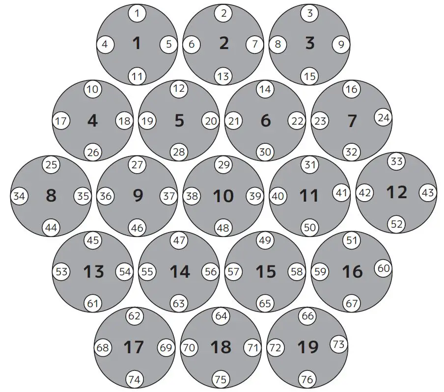
LIGHTING CONSOLE PATCHING GUIDELINES
| CATEGORY | GROUP | PIXELS |
| RGBW Pixel Columns | Column 1 | 8 |
| Column 2 | 4, 13 | |
| Column 3 | 1, 9, 17 | |
| Column 4 | 5, 14 | |
| Column 5 | 2, 10, 18 | |
| Column 6 | 6, 15 | |
| Column 7 | 3, 11, 19 | |
| Column 8 | 7, 16 | |
| Column 9 | 12 | |
| RGBW Pixel Rows | Row 1 | 1 – 3 |
| Row 2 | 4 – 7 | |
| Row 3 | 8 – 12 | |
| Row 4 | 13 – 16 | |
| Row 5 | 17 – 19 | |
| RGBW Pixel Rings | Ring 1 | 1, 2, 3, 7, 12, 16, 19, 18, 17, 13, 8, 4 |
| Ring 2 | 5, 6, 11, 15, 14, 9 | |
| Ring 3 | 10 | |
| Spark LED Rows | Row 1 | 1 – 3 |
| Row 2 | 4 – 9 | |
| Row 3 | 10 – 16 | |
| Row 4 | 17 – 24 | |
| Row 5 | 25 – 33 | |
| Row 6 | 34 – 43 | |
| Row 7 | 44 – 52 | |
| Row 8 | 53 – 60 | |
| Row 9 | 61 – 67 | |
| Row 10 | 68 – 73 | |
| Row 11 | 74 – 76 | |
| Spark LED Rings | Ring 1 | 1, 2, 3, 9, 16, 24, 33, 43, 52, 60, 67, 73, 76, 75, 74, 68, 61, 53, 44, 34, 25, 17, 10, 4 |
| Ring 2 | 5, 6, 7, 8, 15, 23, 32, 41+42, 51, 59, 66, 72, 71, 69, 70, 62, 54, 45, 35+36, 26, 18, 11 | |
| Ring 3 | 13, 14, 22, 31, 50, 58, 65, 64, 63, 55, 46, 27, 19, 12 | |
| Ring 4 | 20, 21, 3, 40, 49, 57, 56, 47, 37, 28, 20 | |
| Ring 5 | 29, 39, 48, 38 |
There are also two additional parts for a primary control of the PROTEUS RAYZOR 1960, which creates four separate control areas for the fixture. It is recommended to create fixture groups on the lighting controller for each area of the fixture. (see below)
| Main Fixture | Primary Pan, Tilt, RGBW Color, Strobe, Dimmer, Zoom, FX Controls |
| RGBW Cells 1-19 | Red, Green, Blue, White per each individual cell |
| Spark LED Main | Primary Spark LED Strobe, Dimmer |
| Spark LEDs 1-76 | Spark LED Dimmer per each individual LED |
SparkLED is not available as a mode in the fixture menu but must be provided as a console control profile for easy programming of the fixture. Use the PROTEUS RAYZOR 1960 in Extended mode and patch appropriate parts of the RGBW Pixels and SparkLED fixtures on your control system to access all 176 channels.
On the lighting controller, patch the two fixture types (RGBW and SparkLED), separating the SparkLEDs into a different ID range. (see below)
RGBW Pixels for Channels 1-98
SparkLEDs for Channels 99-176
ONYX Main and Sub Fixture ID patch example below for a single PROTEUS RAYZOR 1960 fixture.
| ID | TYPE | ADDRESS |
| 1.0 | RGBW Pixels Main | 1 |
| 1.1 | Pixel 1 | 22 |
| 1.2 | Pixel 2 | 26 |
| 1.3 | Pixel 3 | 30 |
| 1.4 | Pixel 4 | 34 |
| 1.5 | Pixel 5 | 38 |
| … | … | … |
| 1.19 | Pixel 19 | 94 |
| 1.20 | Spark LED Main | 98 |
| 101.1 | Spark LED 1 | 101 |
| 101.2 | Spark LED 2 | 102 |
| 101.3 | Spark LED 3 | 103 |
| 101.4 | Spark LED 4 | 104 |
| … | … | … |
| 101.76 | Spark LED 76 | 176 |
ONYX screen shots below illustrate Main and Sub Fixture ID patch for a single PROTEUS RAYZOR 1960 fixture.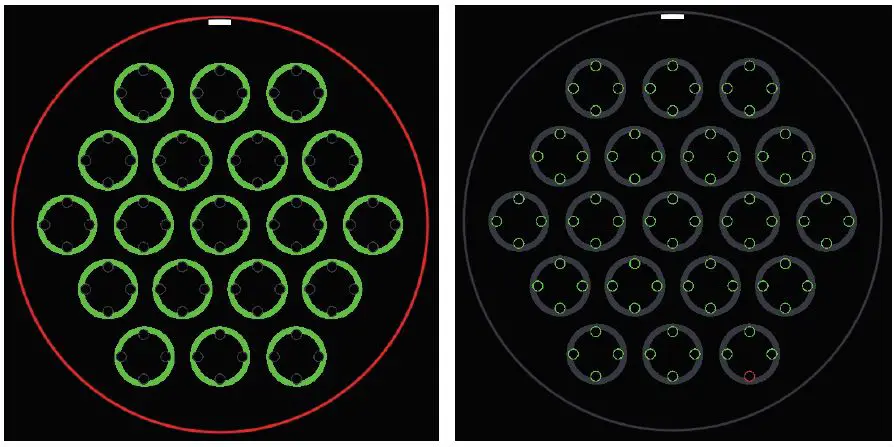
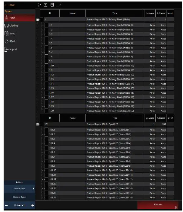
ONYX groups example below for easier selection of a single PROTEUS RAYZOR 1960 fixture.
| Group Name | Group Content |
| All RGBW Pixels Main | 1 |
| All RGBW Pixels | 1.1, 1.2, … 1.20 |
| All Spark LEDs Main | 1.20 |
| All Spark LEDs | 101.1, 101.2, … 101.76 |
ONYX screen shots below illustrate both Primary (top) and SparkLED (bottom) Groups for a single PROTEUS RAYZOR 1960 fixture.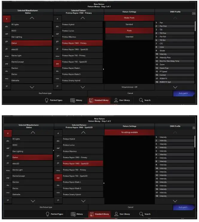
DMX TRAITS
| ELATION PROTEUS RAYZOR 1960 DMX Channel Traits | ||||||
| Supports Software Versions: 2.0.0 | ||||||
| Features subject to change without notice. Rotation direction (clockwise/counter-clockwise) and control of effects depends on head orientation and pan/tilt settings. | ||||||
| CHANNEL | DMX VALUES | FUNCTION | FADE STATUS | DEFAULT VALUE | ||
| STANDARD | PIXELS | EXTENDED | ||||
| 1 | 1 | 1 | 000 – 255 | Pan Movement | Fade | 127 |
| 2 | 2 | 2 | 000 – 255 | Pan Fine Movement | Fade | 127 |
| 3 | 3 | 3 | 000 – 255 | Tilt Movement | Fade | 127 |
| 4 | 4 | 4 | 000 – 255 | Tilt Fine Movement | Fade | 127 |
| 5 | 5 | 5 | Pan Rotate | Fade | 0 | |
| 000 – 002 | Disabled | |||||
| 003 – 126 | Clockwise Rotation, fast to slow | |||||
| 127 – 129 | No Rotation (fixture stops at current position) | |||||
| 130 – 253 | Counter-Clockwise Rotation, slow to fast | |||||
| 254 – 255 | No Rotation (fixture stops at current position) | |||||
| 6 | 6 | 6 | Tilt Rotate | Fade | 0 | |
| 000 – 002 | Disabled | |||||
| 003 – 126 | Clockwise Rotation, fast to slow | |||||
| 127 – 129 | No Rotation (fixture stops at current position) | |||||
| 130 – 253 | Counter-Clockwise Rotation, slow to fast | |||||
| 254 – 255 | No Rotation (fixture stops at current position) | |||||
| 7 | 7 | 7 | CTC | Fade | 0 | |
| 000 – 010 | Disabled | |||||
| 011 – 171 | Color Temperature, 100K steps from 2000K to 10,000K (see CTC Table sec- tion of this manual) | |||||
| 172 – 255 | 10,000K | |||||
| 8 | 8 | 8 | Color Wheel | Snap | 0 | |
| 000 – 009 | Open | |||||
| 010 – 014 | Red | |||||
| 015 – 019 | Red Orange | |||||
| 020 – 024 | Light Amber | |||||
| 025 – 029 | Yellow Amber | |||||
| 030 – 034 | Greenish Yellow | |||||
| 035 – 039 | Light Yellow Green | |||||
| 040 – 044 | Dark Yellow Green | |||||
| 045 – 049 | Green | |||||
| CONTINUED ON NEXT PAGE | ||||||
| CHANNEL | DMX VALUES | FUNCTION | FADE STATUS | DEFAULT VALUE | ||
| STANDARD | PIXELS | EXTENDED | ||||
| 8 | 8 | 8 | Color Wheel (continued) | Snap | 0 | |
| 050 – 054 | Teal | |||||
| 055 – 059 | Cyan | |||||
| 060 – 064 | Light Blue | |||||
| 065 – 069 | Aqua | |||||
| 070 – 074 | Dark Aqua | |||||
| 075 – 079 | Green Blue | |||||
| 080 – 084 | Light Lavender | |||||
| 085 – 089 | Dark Purple | |||||
| 090 – 094 | Medium Purple | |||||
| 095 – 099 | Mid Rose | |||||
| 100 – 104 | Mauve | |||||
| 105 – 109 | Nice Magenta | |||||
| 110 – 114 | Warm Magenta | |||||
| 115 – 119 | Light Red | |||||
| 120 – 124 | Straw | |||||
| 125 – 129 | Dark CTB | |||||
| 130 – 134 | Light Green | |||||
| 135 – 139 | Purple | |||||
| 140 – 144 | Lighter Purple | |||||
| 145 – 149 | Pink | |||||
| 150 – 154 | Rose | |||||
| 155 – 159 | White | |||||
| 164 – 174 | No Function | |||||
| 175 – 179 | Open | |||||
| Color Scroll | ||||||
| 180 – 201 | Clockwise Scroll, fast to slow | |||||
| 202 – 207 | Stop | |||||
| 208 – 229 | Counter-Clockwise Scroll, slow to fast | |||||
| 230 – 234 | Open | |||||
| Random Slots | ||||||
| 235 – 239 | Fast | |||||
| 240 – 244 | Medium | |||||
| 245 – 249 | Slow | |||||
| 250 – 255 | Open | |||||
| CONTINUED ON NEXT PAGE | ||||||
| CHANNEL | DMX VALUES | FUNCTION | FADE STATUS | DEFAULT VALUE | ||
| STANDARD | PIXELS | EXTENDED | ||||
| 9 | 9 | 9 | Strobe | Snap | 50 | |
| 000 – 031 | Shutter Closed | |||||
| 032 – 063 | Shutter Open | |||||
| 064 – 095 | Strobe, slow to fast | |||||
| 096 – 127 | Fast Close, Slow Open | |||||
| 128 – 159 | Fast Open, Slow Close | |||||
| 160 – 191 | Pulse Effects | |||||
| 192 – 223 | Random Strobe, slow to fast | |||||
| 224 – 255 | Shutter Open | |||||
| 10 | 10 | 10 | 000 – 255 | Dimmer, 0% to 100% | Fade | 0 |
| 11 | 11 | 11 | 000 – 255 | Dimmer Fine | Fade | 0 |
| 12 | 12 | 12 | Dim Modes | Snap | 0 | |
| 000 – 020 | Standard | |||||
| 021 – 040 | Stage | |||||
| 041 – 060 | TV | |||||
| 061 – 080 | Architectural | |||||
| 081 – 100 | Theatre | |||||
| 101 – 120 | Stage 2 | |||||
| Dimmer Delay Time | ||||||
| 121 | 0s | |||||
| 122 | 0.1s | |||||
| 123 | 0.2s | |||||
| 124 | 0.3s | |||||
| 125 | 0.4s | |||||
| 126 | 0.5s | |||||
| 127 | 0.6s | |||||
| 128 | 0.7s | |||||
| 129 | 0.8s | |||||
| 130 | 0.9s | |||||
| 131 | 1.0s | |||||
| 132 | 1.5s | |||||
| 133 | 2.0s | |||||
| 134 | 3.0s | |||||
| 135 | 4.0s | |||||
| 136 | 5.0s | |||||
| 137 | 6.0s | |||||
| 138 | 7.0s | |||||
| 139 | 8.0s | |||||
| 140 | 9.0s | |||||
| 141 | 10.0s | |||||
| 142 – 255 | Idle | |||||
| CONTINUED ON NEXT PAGE | ||||||
| CHANNEL | DMX VALUES | FUNCTION | FADE STATUS | DEFAULT VALUE | ||
| STANDARD | PIXELS | EXTENDED | ||||
| 13 | 13 | 13 | Zoom | Fade | 0 | |
| 000 – 245 | Zoom, wide to narrow | |||||
| 246 – 255 | Overdrive, minimum to maximum | |||||
| 14 | 14 | 000 – 255 | Zoom Fine | Fade | 0 | |
| 15 | 15 | Pan/Tilt Speed | Snap | 0 | ||
| 000 – 225 | Speed, maximum to minimum | |||||
| 226 – 235 | Blackout when pan/tilt moves | |||||
| 236 – 245 | Blackout when all wheels change | |||||
| 246 – 255 | No function | |||||
| 14 | 16 | 16 | Control | Snap | 0 | |
| 000 – 010 | Idle | |||||
| 011 – 012 | Pan/Tilt Shortest Path | |||||
| 013 – 014 | Pan/Tilt Continue Path (default) | |||||
| 015 – 016 | Pan Range 540 (default) | |||||
| 017 – 018 | Pan Range 360 | |||||
| 019 – 020 | Tilt Range 270 (default) | |||||
| 021 – 022 | Tilt Range 360 | |||||
| 023 – 039 | Idle | |||||
| 040 – 044 | Fan Mode Mute | |||||
| 045 – 049 | Fan Mode Studio | |||||
| 050 – 059 | Fan Mode Silent | |||||
| 060 – 069 | Fan Mode High | |||||
| 070 – 079 | Fan Mode Auto (default) | |||||
| 080 – 084 | Reset All | |||||
| 085 – 087 | Reset Movement | |||||
| 088 – 091 | Reset Zoom | |||||
| 092 – 099 | Idle | |||||
| Refresh Rate (Hz) | ||||||
| 100 | 900 | |||||
| 101 | 910 | |||||
| 102 | 920 | |||||
| 103 | 930 | |||||
| 104 | 940 | |||||
| 105 | 950 | |||||
| 106 | 960 | |||||
| 107 | 970 | |||||
| 108 | 980 | |||||
| 109 | 990 | |||||
| 110 | 1000 | |||||
| 111 | 1010 | |||||
| 112 | 1020 | |||||
| CONTINUED ON NEXT PAGE | ||||||
| CHANNEL | DMX VALUES | FUNCTION | FADE STATUS | DEFAULT VALUE | ||
| STANDARD | PIXELS | EXTENDED | ||||
| 14 | 16 | 16 | Refresh (Hz) (continued) |
Snap |
0 | |
| 113 | 1030 | |||||
| 114 | 1040 | |||||
| 115 | 1050 | |||||
| 116 | 1060 | |||||
| 117 | 1070 | |||||
| 118 | 1080 | |||||
| 119 | 1090 | |||||
| 120 | 1100 | |||||
| 121 | 1110 | |||||
| 122 | 1120 | |||||
| 123 | 1130 | |||||
| 124 | 1140 | |||||
| 125 | 1150 | |||||
| 126 | 1160 | |||||
| 127 | 1170 | |||||
| 128 | 1180 | |||||
| 129 | 1190 | |||||
| 130 | 1200 | |||||
| 131 | 1210 | |||||
| 132 | 1220 | |||||
| 133 | 1230 | |||||
| 134 | 1240 | |||||
| 135 | 1250 | |||||
| 136 | 1260 | |||||
| 137 | 1270 | |||||
| 138 | 1280 | |||||
| 139 | 1290 | |||||
| 140 | 1300 | |||||
| 141 | 1310 | |||||
| 142 | 1320 | |||||
| 143 | 1330 | |||||
| 144 | 1340 | |||||
| 145 | 1350 | |||||
| 146 | 1360 | |||||
| 147 | 1370 | |||||
| 148 | 1380 | |||||
| 149 | 1390 | |||||
| 150 | 1400 | |||||
| 151 | 1410 | |||||
| 152 | 1420 | |||||
| CONTINUED ON NEXT PAGE | ||||||
| CHANNEL | DMX VALUES | FUNCTION | FADE STATUS | DEFAULT VALUE | ||
| STANDARD | PIXELS | EXTENDED | ||||
|
14 |
16 |
16 | Refresh (Hz) (continued) |
Snap |
0 | |
| 153 | 1430 | |||||
| 154 | 1440 | |||||
| 155 | 1450 | |||||
| 156 | 1460 | |||||
| 157 | 1470 | |||||
| 158 | 1480 | |||||
| 159 | 1490 | |||||
| 160 | 1500 | |||||
| 161 | 2500 | |||||
| 162 | 4000 | |||||
| 163 | 5000 | |||||
| 164 | 6000 | |||||
| 165 | 10000 | |||||
| 166 | 15000 | |||||
| 167 | 20000 | |||||
| 168 | 25000 | |||||
| 169 – 192 | Idle | |||||
| 193 – 194 | Hibernate Off | |||||
| 195 – 196 | Hibernate On | |||||
| 197 – 198 | Sun Protection On | |||||
| 199 – 200 | Sun Protection Off | |||||
| 201 – 210 | Dimmer Curve Linear (default) | |||||
| 211 – 220 | Dimmer Curve Square | |||||
| 221 – 230 | Dimmer Curve Inverse Square | |||||
| 231 – 240 | Dimmer Curve S-Curve | |||||
| 241 – 242 | Zoom Speed – Slow | |||||
| 243 – 244 | Zoom Speed – Fast (default) | |||||
| 245 – 249 | Idle | |||||
| 250 – 251 | Display Off | |||||
| 252 – 253 | Display On | |||||
| 254 – 255 | Idle | |||||
| 15 | 17 | 17 | 000 – 255 | RGBW FX (see RGBW Pixel FX Table section of this manual) | Snap | 0 |
| 16 | 18 | 18 | RGBW FX Speed | Fade | 160 | |
| 000 – 126 | Reverse, fast to slow | |||||
| 127 – 128 | Stop | |||||
| 129 – 255 | Forward, slow to fast | |||||
| 17 | 19 | 19 | 000 – 255 | Spark LED FX (see Spark LED FX Table section of this manual) | Snap | 0 |
| CONTINUED ON NEXT PAGE | ||||||
| CHANNEL | DMX VALUES | FUNCTION | FADE STATUS | DEFAULT VALUE | ||
| STANDARD | PIXELS | EXTENDED | ||||
| 18 | 20 | 20 | Spark LED FX Speed | Fade | 160 | |
| 000 – 126 | Reverse, fast to slow | |||||
| 127 – 128 | Stop | |||||
| 129 – 255 | Forward, slow to fast | |||||
| 19 | 21 | 21 | FX Offset | Snap | 0 | |
| 000 | Idle | |||||
| 001 – 035 | Fixture Offset, 10 degrees to 350 degrees | |||||
| 036 | Synchronized | |||||
| 037 – 100 | No Function | |||||
| 101 – 120 | Random Fixture Offset | |||||
| 121 – 140 | Random Pixel Order | |||||
| 141 – 255 | Random Steps | |||||
| 20 | 22 | 22 | 000 – 255 | Red, 0% to 100% | Fade | 255 |
| 21 | 23 | 23 | 000 – 255 | Green, 0% to 100% | Fade | 255 |
| 22 | 24 | 24 | 000 – 255 | Blue, 0% to 100% | Fade | 255 |
| 23 | 25 | 25 | 000 – 255 | White, 0% to 100% | Fade | 255 |
| 26 | 26 | 000 – 255 | Red 2, 0% to 100% | Fade | 255 | |
| 27 | 27 | 000 – 255 | Green 2, 0% to 100% | Fade | 255 | |
| 28 | 28 | 000 – 255 | Blue 2, 0% to 100% | Fade | 255 | |
| 29 | 29 | 000 – 255 | White 2, 0% to 100% | Fade | 255 | |
| 30 | 30 | 000 – 255 | Red 3, 0% to 100% | Fade | 255 | |
| 31 | 31 | 000 – 255 | Green 3, 0% to 100% | Fade | 255 | |
| 32 | 32 | 000 – 255 | Blue 3, 0% to 100% | Fade | 255 | |
| 33 | 33 | 000 – 255 | White 3, 0% to 100% | Fade | 255 | |
| 34 | 34 | 000 – 255 | Red 4, 0% to 100% | Fade | 255 | |
| 35 | 35 | 000 – 255 | Green 4, 0% to 100% | Fade | 255 | |
| 36 | 36 | 000 – 255 | Blue 4, 0% to 100% | Fade | 255 | |
| 37 | 37 | 000 – 255 | White 4, 0% to 100% | Fade | 255 | |
| 38 | 38 | 000 – 255 | Red 5, 0% to 100% | Fade | 255 | |
| 39 | 39 | 000 – 255 | Green 5, 0% to 100% | Fade | 255 | |
| 40 | 40 | 000 – 255 | Blue 5, 0% to 100% | Fade | 255 | |
| 41 | 41 | 000 – 255 | White 5, 0% to 100% | Fade | 255 | |
| 42 | 42 | 000 – 255 | Red 6, 0% to 100% | Fade | 255 | |
| 43 | 43 | 000 – 255 | Green 6, 0% to 100% | Fade | 255 | |
| 44 | 44 | 000 – 255 | Blue 6, 0% to 100% | Fade | 255 | |
| 45 | 45 | 000 – 255 | White 6, 0% to 100% | Fade | 255 | |
| 46 | 46 | 000 – 255 | Red 7, 0% to 100% | Fade | 255 | |
| 47 | 47 | 000 – 255 | Green 7, 0% to 100% | Fade | 255 | |
| 48 | 48 | 000 – 255 | Blue 7, 0% to 100% | Fade | 255 | |
| 49 | 49 | 000 – 255 | White 7, 0% to 100% | Fade | 255 | |
| CONTINUED ON NEXT PAGE | ||||||
| CHANNEL | DMX VALUES | FUNCTION | FADE STATUS | DEFAULT VALUE | ||
| STANDARD | PIXELS | EXTENDED | ||||
| 50 | 50 | 000 – 255 | Red 8, 0% to 100% | Fade | 255 | |
| 51 | 51 | 000 – 255 | Green 8, 0% to 100% | Fade | 255 | |
| 52 | 52 | 000 – 255 | Blue 8, 0% to 100% | Fade | 255 | |
| 53 | 53 | 000 – 255 | White 8, 0% to 100% | Fade | 255 | |
| 54 | 54 | 000 – 255 | Red 9, 0% to 100% | Fade | 255 | |
| 55 | 55 | 000 – 255 | Green 9, 0% to 100% | Fade | 255 | |
| 56 | 56 | 000 – 255 | Blue 9, 0% to 100% | Fade | 255 | |
| 57 | 57 | 000 – 255 | White 9, 0% to 100% | Fade | 255 | |
| 58 | 58 | 000 – 255 | Red 10, 0% to 100% | Fade | 255 | |
| 59 | 59 | 000 – 255 | Green 10, 0% to 100% | Fade | 255 | |
| 60 | 60 | 000 – 255 | Blue 10, 0% to 100% | Fade | 255 | |
| 61 | 61 | 000 – 255 | White 10, 0% to 100% | Fade | 255 | |
| 62 | 62 | 000 – 255 | Red 11, 0% to 100% | Fade | 255 | |
| 63 | 63 | 000 – 255 | Green 11, 0% to 100% | Fade | 255 | |
| 64 | 64 | 000 – 255 | Blue 11, 0% to 100% | Fade | 255 | |
| 65 | 65 | 000 – 255 | White 11, 0% to 100% | Fade | 255 | |
| 66 | 66 | 000 – 255 | Red 12, 0% to 100% | Fade | 255 | |
| 67 | 67 | 000 – 255 | Green 12, 0% to 100% | Fade | 255 | |
| 68 | 68 | 000 – 255 | Blue 12, 0% to 100% | Fade | 255 | |
| 69 | 69 | 000 – 255 | White 12, 0% to 100% | Fade | 255 | |
| 70 | 70 | 000 – 255 | Red 13, 0% to 100% | Fade | 255 | |
| 71 | 71 | 000 – 255 | Green 13, 0% to 100% | Fade | 255 | |
| 72 | 72 | 000 – 255 | Blue 13, 0% to 100% | Fade | 255 | |
| 73 | 73 | 000 – 255 | White 13, 0% to 100% | Fade | 255 | |
| 74 | 74 | 000 – 255 | Red 14, 0% to 100% | Fade | 255 | |
| 75 | 75 | 000 – 255 | Green 14, 0% to 100% | Fade | 255 | |
| 76 | 76 | 000 – 255 | Blue 14, 0% to 100% | Fade | 255 | |
| 77 | 77 | 000 – 255 | White 14, 0% to 100% | Fade | 255 | |
| 78 | 78 | 000 – 255 | Red 15, 0% to 100% | Fade | 255 | |
| 79 | 79 | 000 – 255 | Green 15, 0% to 100% | Fade | 255 | |
| 80 | 80 | 000 – 255 | Blue 15, 0% to 100% | Fade | 255 | |
| 81 | 81 | 000 – 255 | White 15, 0% to 100% | Fade | 255 | |
| 82 | 82 | 000 – 255 | Red 16, 0% to 100% | Fade | 255 | |
| 83 | 83 | 000 – 255 | Green 16, 0% to 100% | Fade | 255 | |
| 84 | 84 | 000 – 255 | Blue 16, 0% to 100% | Fade | 255 | |
| 85 | 85 | 000 – 255 | White 16, 0% to 100% | Fade | 255 | |
| 86 | 86 | 000 – 255 | Red 17, 0% to 100% | Fade | 255 | |
| 87 | 87 | 000 – 255 | Green 17, 0% to 100% | Fade | 255 | |
| 88 | 88 | 000 – 255 | Blue 17, 0% to 100% | Fade | 255 | |
| 89 | 89 | 000 – 255 | White 17, 0% to 100% | Fade | 255 | |
| 90 | 90 | 000 – 255 | Red 18, 0% to 100% | Fade | 255 | |
| CONTINUED ON NEXT PAGE | ||||||
| CHANNEL | DMX VALUES | FUNCTION | FADE STATUS | DEFAULT VALUE | ||
| STANDARD | PIXELS | EXTENDED | ||||
| 91 | 91 | 000 – 255 | Green 18, 0% to 100% | Fade | 255 | |
| 92 | 92 | 000 – 255 | Blue 18, 0% to 100% | Fade | 255 | |
| 93 | 93 | 000 – 255 | White 18, 0% to 100% | Fade | 255 | |
| 94 | 94 | 000 – 255 | Red 19, 0% to 100% | Fade | 255 | |
| 95 | 95 | 000 – 255 | Green 19, 0% to 100% | Fade | 255 | |
| 96 | 96 | 000 – 255 | Blue 19, 0% to 100% | Fade | 255 | |
| 97 | 97 | 000 – 255 | White 19, 0% to 100% | Fade | 255 | |
| 24 | 98 | 98 | Spark LED Strobe | Snap | 50 | |
| 000 – 031 | Shutter Closed | |||||
| 032 – 063 | Shutter Open | |||||
| 064 – 095 | Strobe, slow to fast | |||||
| 096 – 127 | Fast Close, Slow Open | |||||
| 128 – 159 | Fast Open, Slow Close | |||||
| 160 – 191 | Pulse Effects | |||||
| 192 – 222 | Random Strobe All, slow to fast | |||||
| 223 – 254 | Random Strobe Pixels, slow to fast | |||||
| 255 | Sync Dim and Strobe with Main | |||||
| 25 | 99 | 99 | 000 – 255 | Spark LED Dimmer, 0% to 100% | Fade | 0 |
| 100 | 100 | 000 – 255 | Spark LED Dimmer Fine | Fade | 0 | |
| 101 | 000 – 255 | Spark LED Dimmer 1, 0% to 100% | Fade | 255 | ||
| 102 | 000 – 255 | Spark LED Dimmer 2, 0% to 100% | Fade | 255 | ||
| 103 | 000 – 255 | Spark LED Dimmer 3, 0% to 100% | Fade | 255 | ||
| 104 | 000 – 255 | Spark LED Dimmer 4, 0% to 100% | Fade | 255 | ||
| 105 | 000 – 255 | Spark LED Dimmer 5, 0% to 100% | Fade | 255 | ||
| 106 | 000 – 255 | Spark LED Dimmer 6, 0% to 100% | Fade | 255 | ||
| 107 | 000 – 255 | Spark LED Dimmer 7, 0% to 100% | Fade | 255 | ||
| 108 | 000 – 255 | Spark LED Dimmer 8, 0% to 100% | Fade | 255 | ||
| 109 | 000 – 255 | Spark LED Dimmer 9, 0% to 100% | Fade | 255 | ||
| 110 | 000 – 255 | Spark LED Dimmer 10, 0% to 100% | Fade | 255 | ||
| 111 | 000 – 255 | Spark LED Dimmer 11, 0% to 100% | Fade | 255 | ||
| 112 | 000 – 255 | Spark LED Dimmer 12, 0% to 100% | Fade | 255 | ||
| 113 | 000 – 255 | Spark LED Dimmer 13, 0% to 100% | Fade | 255 | ||
| 114 | 000 – 255 | Spark LED Dimmer 14, 0% to 100% | Fade | 255 | ||
| 115 | 000 – 255 | Spark LED Dimmer 15, 0% to 100% | Fade | 255 | ||
| 116 | 000 – 255 | Spark LED Dimmer 16, 0% to 100% | Fade | 255 | ||
| 117 | 000 – 255 | Spark LED Dimmer 17, 0% to 100% | Fade | 255 | ||
| 118 | 000 – 255 | Spark LED Dimmer 18, 0% to 100% | Fade | 255 | ||
| 119 | 000 – 255 | Spark LED Dimmer 19, 0% to 100% | Fade | 255 | ||
| 120 | 000 – 255 | Spark LED Dimmer 20, 0% to 100% | Fade | 255 | ||
| 121 | 000 – 255 | Spark LED Dimmer 21, 0% to 100% | Fade | 255 | ||
| 122 | 000 – 255 | Spark LED Dimmer 22, 0% to 100% | Fade | 255 | ||
| CONTINUED ON NEXT PAGE | ||||||
| CHANNEL | DMX VALUES | FUNCTION | FADE STATUS | DEFAULT VALUE | ||
| STANDARD | PIXELS | EXTENDED | ||||
| 123 | 000 – 255 | Spark LED Dimmer 23, 0% to 100% | Fade | 255 | ||
| 124 | 000 – 255 | Spark LED Dimmer 24, 0% to 100% | Fade | 255 | ||
| 125 | 000 – 255 | Spark LED Dimmer 25, 0% to 100% | Fade | 255 | ||
| 126 | 000 – 255 | Spark LED Dimmer 26, 0% to 100% | Fade | 255 | ||
| 127 | 000 – 255 | Spark LED Dimmer 27, 0% to 100% | Fade | 255 | ||
| 128 | 000 – 255 | Spark LED Dimmer 28, 0% to 100% | Fade | 255 | ||
| 129 | 000 – 255 | Spark LED Dimmer 29, 0% to 100% | Fade | 255 | ||
| 130 | 000 – 255 | Spark LED Dimmer 30, 0% to 100% | Fade | 255 | ||
| 131 | 000 – 255 | Spark LED Dimmer 31, 0% to 100% | Fade | 255 | ||
| 132 | 000 – 255 | Spark LED Dimmer 32, 0% to 100% | Fade | 255 | ||
| 133 | 000 – 255 | Spark LED Dimmer 33, 0% to 100% | Fade | 255 | ||
| 134 | 000 – 255 | Spark LED Dimmer 34, 0% to 100% | Fade | 255 | ||
| 135 | 000 – 255 | Spark LED Dimmer 35, 0% to 100% | Fade | 255 | ||
| 136 | 000 – 255 | Spark LED Dimmer 36, 0% to 100% | Fade | 255 | ||
| 137 | 000 – 255 | Spark LED Dimmer 37, 0% to 100% | Fade | 255 | ||
| 138 | 000 – 255 | Spark LED Dimmer 38, 0% to 100% | Fade | 255 | ||
| 139 | 000 – 255 | Spark LED Dimmer 39, 0% to 100% | Fade | 255 | ||
| 140 | 000 – 255 | Spark LED Dimmer 40, 0% to 100% | Fade | 255 | ||
| 141 | 000 – 255 | Spark LED Dimmer 41, 0% to 100% | Fade | 255 | ||
| 142 | 000 – 255 | Spark LED Dimmer 42, 0% to 100% | Fade | 255 | ||
| 143 | 000 – 255 | Spark LED Dimmer 43, 0% to 100% | Fade | 255 | ||
| 144 | 000 – 255 | Spark LED Dimmer 44, 0% to 100% | Fade | 255 | ||
| 145 | 000 – 255 | Spark LED Dimmer 45, 0% to 100% | Fade | 255 | ||
| 146 | 000 – 255 | Spark LED Dimmer 46, 0% to 100% | Fade | 255 | ||
| 147 | 000 – 255 | Spark LED Dimmer 47, 0% to 100% | Fade | 255 | ||
| 148 | 000 – 255 | Spark LED Dimmer 48, 0% to 100% | Fade | 255 | ||
| 149 | 000 – 255 | Spark LED Dimmer 49, 0% to 100% | Fade | 255 | ||
| 150 | 000 – 255 | Spark LED Dimmer 50, 0% to 100% | Fade | 255 | ||
| 151 | 000 – 255 | Spark LED Dimmer 51, 0% to 100% | Fade | 255 | ||
| 152 | 000 – 255 | Spark LED Dimmer 52, 0% to 100% | Fade | 255 | ||
| 153 | 000 – 255 | Spark LED Dimmer 53, 0% to 100% | Fade | 255 | ||
| 154 | 000 – 255 | Spark LED Dimmer 54, 0% to 100% | Fade | 255 | ||
| 155 | 000 – 255 | Spark LED Dimmer 55, 0% to 100% | Fade | 255 | ||
| 156 | 000 – 255 | Spark LED Dimmer 56, 0% to 100% | Fade | 255 | ||
| 157 | 000 – 255 | Spark LED Dimmer 57, 0% to 100% | Fade | 255 | ||
| 158 | 000 – 255 | Spark LED Dimmer 58, 0% to 100% | Fade | 255 | ||
| 159 | 000 – 255 | Spark LED Dimmer 59, 0% to 100% | Fade | 255 | ||
| 160 | 000 – 255 | Spark LED Dimmer 60, 0% to 100% | Fade | 255 | ||
| 161 | 000 – 255 | Spark LED Dimmer 61, 0% to 100% | Fade | 255 | ||
| 162 | 000 – 255 | Spark LED Dimmer 62, 0% to 100% | Fade | 255 | ||
| 163 | 000 – 255 | Spark LED Dimmer 63, 0% to 100% | Fade | 255 | ||
| CONTINUED ON NEXT PAGE | ||||||
| CHANNEL | DMX VALUES | FUNCTION | FADE STATUS | DEFAULT VALUE | ||
| STANDARD | PIXELS | EXTENDED | ||||
| 164 | 000 – 255 | Spark LED Dimmer 64, 0% to 100% | Fade | 255 | ||
| 165 | 000 – 255 | Spark LED Dimmer 65, 0% to 100% | Fade | 255 | ||
| 166 | 000 – 255 | Spark LED Dimmer 66, 0% to 100% | Fade | 255 | ||
| 167 | 000 – 255 | Spark LED Dimmer 67, 0% to 100% | Fade | 255 | ||
| 168 | 000 – 255 | Spark LED Dimmer 68, 0% to 100% | Fade | 255 | ||
| 169 | 000 – 255 | Spark LED Dimmer 69, 0% to 100% | Fade | 255 | ||
| 170 | 000 – 255 | Spark LED Dimmer 70, 0% to 100% | Fade | 255 | ||
| 171 | 000 – 255 | Spark LED Dimmer 71, 0% to 100% | Fade | 255 | ||
| 172 | 000 – 255 | Spark LED Dimmer 72, 0% to 100% | Fade | 255 | ||
| 173 | 000 – 255 | Spark LED Dimmer 73, 0% to 100% | Fade | 255 | ||
| 174 | 000 – 255 | Spark LED Dimmer 74, 0% to 100% | Fade | 255 | ||
| 175 | 000 – 255 | Spark LED Dimmer 75, 0% to 100% | Fade | 255 | ||
| 176 | 000 – 255 | Spark LED Dimmer 76, 0% to 100% | Fade | 255 | ||
FX GENER ATOR GUIDELINES
Selection and control of the integrated FX on the Proteus RAyzor 1960 is found in the Main Fixture section. All FX are available, even in the DMX control modes with the lowest channel count. For your convenience, these functions are summarized below. Please refer to the DMX Traits section of this manual for detailed information.
| DMX VALUES | FUNCTION |
| 000 – 255 | RGBW FX (see RGBW Pixel FX Table section of this manual) |
| RGBW FX Speed | |
| 000 – 126 | Reverse, fast to slow |
| 127 – 128 | Stop |
| 129 – 255 | Forward, slow to fast |
| 000 – 255 | Spark LED FX (see Spark LED FX Table section of this manual) |
| Spark LED FX Speed | |
| 000 – 126 | Reverse, fast to slow |
| 127 – 128 | Stop |
| 129 – 255 | Forward, slow to fast |
FX for RGBW and Spark LED contain a selection channel to recall the desired pattern. The pattern direction and speed is then adjusted using the associated Speed channels. FX can run in forward or reverse, and can also be frozen at any time by using “Stop”. The FX tables show the available patterns which are grouped for easier browsing. The first 10 DMX steps of the FX channel are used to change the type of curve for smooth or stepped FX. Once a curve is selected, it will be used for all FX recalled afterwards. When programming cues for fixtures, the user must make sure to change the curve first before selecting the pattern. The fixture defaults to the Sinewave pattern after every power cycle. See the Waveforms section of this manual for the available waveforms.
RGBW PIXEL FX TABLE
| FX TYPE | SLOT | DMX | FX NAME | FX ADJUSTMENT | NOTES |
| Off | 000 | Off | |||
| Waveform | 1 | 001 | Sinewave – Cross (default) | In and out fade start at the same time | |
| 2 | 002 | Sinewave – Full | In fade completes, then out fade com- pletes | ||
| 3 | 003 | Sawtooth – Cross | In and out fade start at the same time | ||
| 4 | 004 | Sawtooth – Full | In fade complete, then out fade com- pletes | ||
| 5 | 005 | Ramp Up | |||
| 6 | 006 | Ramp Down | |||
| 7 | 007 | Steps | |||
| 8-10 | 008 – 010 | Not in use | |||
| Intensity | 11 | 011 | Single | Reverse, Stop, Forward | 1, 2, 3…19 |
| 12 | 012 | Single Bounce | Reverse, Stop, Forward | 1, 2, 3…19, 18, 17, 16…1 | |
| 13 | 013 | Snake | Reverse, Stop, Forward | 1, 2, 3, 7, 12, 16, 19, 18, 17, 13, 8, 4, 5, 6, 11, 15, 14, 9, 10 | |
| 14 | 014 | Snake Bounce | Reverse, Stop, Forward | Snake forward once and reverses | |
| 15 | 015 | Rows | Reverse, Stop, Forward | Row1, 2, 3, 4, 5 | |
| 16 | 016 | Rows Bounce | Reverse, Stop, Forward | Rows forward once and reverses | |
| 17 | 017 | Column | Reverse, Stop, Forward | One column per step | |
| 18 | 018 | Column Bounce | Reverse, Stop, Forward | One column per step forward once and reverses | |
| 19 | 019 | Not in use | |||
| 20 | 020 | Slash | Reverse, Stop, Forward | 1+4+8, 2+5+9+13, 3+6+10+14+17, 7+11+15+18, 12+16+19 | |
| 21 | 021 | Backslash | Reverse, Stop, Forward | 8+13+17, 4+9+14+18, 1+5+10+15+19, 2+6+11+16, 3+7+12 | |
| 22 | 022 | Slash Back | Reverse, Stop, Forward | 1+4+8, 2+5+9+13, 3+6+10+14+17, 7+11+15+18, 12+16+19, 8+13+17, 4+9+14+18, 1+5+10+15+19, 2+6+11+16, 3+7+12 | |
| 23 | 023 | <> | Reverse, Stop, Forward | 1+4+8+13+17, 3+7+12+16+19 | |
| 24 | 024 | >< | Reverse, Stop, Forward | 1+5+10+14+17, 3+6+10+15+19 | |
| 25 | 025 | >> | Reverse, Stop, Forward | 8, 4+9+13, 1+5+10+14+17, 2+6+11+15+18, 3+7+12+16+19 | |
| 26 | 026 | << | Reverse, Stop, Forward | 12, 7+11+16, 3+6+10+15+19, 2+5+9+14+18, 1+4+8+13+17, | |
| CONTINUED ON NEXT PAGE | |||||
| FX TYPE | SLOT | DMX | FX NAME | FX ADJUSTMENT | NOTES |
| Intensity (continued) | 27 | 027 | Rotating Bar | Reverse, Stop, Forward | 8+9+10+11+12, 13+10+7, 17+14+10+6+3, 2+10+18, 1+5+10+15+19, 4+10+16 |
| 28 | 028 | Ring 1 Chase | Reverse, Stop, Forward | One pixel at a time in RGBW ring 1 | |
| 29 | 029 | Ring 2 Chase | Reverse, Stop, Forward | One pixel at a time in RGBW ring 2 | |
| 30-37 | 030 – 037 | Not in use | |||
| 38 | 038 | 2 Pixels | Reverse, Stop, Forward | Any two random pixels per step | |
| 39 | 039 | 3 Pixels | Reverse, Stop, Forward | Any three random pixels per step | |
| 40 | 040 | 4 Pixels | Reverse, Stop, Forward | Any four random pixels per step | |
| 41 | 041 | 1,2,3,4 Pixels | Reverse, Stop, Forward | Randomly pick 1, then 2, then 3, then 4 pixels | |
| 42 | 042 | Ring Build | Reverse, Stop, Forward | Builds ring 1, then ring 2, then ring 3, one pixel at a time | |
| 43 | 043 | Ring Build Erase | Reverse, Stop, Forward | Builds ring 1, then ring 2, then ring 3, one pixel at a time; then erases ring 1, then ring 2, then ring 3, one pixel at a time | |
| 44 | 044 | Ring Build Erase 2 | Reverse, Stop, Forward | Builds ring 1, then ring 2, then ring 3, one pixel at a time; then erases ring 3, then ring 2, then ring 1, one pixel at a time | |
| 45-56 | 045 – 056 | Not in use | |||
| 57 | 057 | Alternate | Reverse, Stop, Forward | Evenly alternate (tick/tock/tick/tock) between RGBW pixel at full and Spark LEDs at full; keeps all colors, strobes, and intensities as set in DMX | |
| 58 | 058 | Burst Spark LED | Reverse, Stop, Forward | Toggles between RGBW Pixel at full (long) and Spark LEDs at full (short flash); keeps all colors, strobes, and intensities as set in DMX | |
| 59 | 059 | Strobe Alternate | Reverse, Stop, Forward | Strobes between RGBW Pixel at full (short, then off) and Spark LEDs at full (short, then off); keeps all colors, strobes, and intensities as set in DMX | |
| 60 | 060 | Lens/Spark LED Alterate | Reverse, Stop, Forward | Random Lens at full, then different Random Lens SparkLEDs at full; keeps all colors, strobes, and intensities as set in DMX | |
| 61- 100 | 061 – 100 | Not in use | |||
| CONTINUED ON NEXT PAGE | |||||
| FX TYPE | SLOT | DMX | FX NAME | FX ADJUSTMENT | NOTES |
| Static Patterns | 101 | 101 | Row 1 | Disabled | |
| 102 | 102 | Row 2 | Disabled | ||
| 103 | 103 | Row 3 | Disabled | ||
| 104 | 104 | Row 4 | Disabled | ||
| 105 | 105 | Row 5 | Disabled | ||
| 106 | 106 | Column 1 | Disabled | ||
| 107 | 107 | Column 2 | Disabled | ||
| 108 | 108 | Column 3 | Disabled | ||
| 109 | 109 | Column 4 | Disabled | ||
| 110 | 110 | Column 5 | Disabled | ||
| 111 | 111 | Column 6 | Disabled | ||
| 112 | 112 | Column 7 | Disabled | ||
| 113 | 113 | Column 8 | Disabled | ||
| 114 | 114 | Column 9 | Disabled | ||
| 115 | 115 | Ring 1 | Disabled | ||
| 116 | 116 | Ring 2 | Disabled | ||
| 117 | 117 | Ring 3 | Disabled | ||
| 118 | 118 | X | Disabled | 1, 5, 10, 15, 19, 17, 14, 6, 3 | |
| 119 | 119 | Slash | Disabled | 1, 5, 10, 15, 19 | |
| 120 | 120 | Backslash | Disabled | 3, 6, 10, 14, 17 | |
| 121 | 121 | Arrow Left | Disabled | 1, 4, 8, 13, 17, 9, 10, 11, 12 | |
| 122 | 122 | Arrow Right | Disabled | 3, 7, 12, 16, 19, 8, 9, 10, 11 | |
| 123 | 123 | < | Disabled | 1, 2, 4, 5, 8, 9, 13, 14, 17, 18 | |
| 124 | 124 | > | Disabled | 2, 3, 6, 7, 11, 12, 15, 16, 18, 19 | |
| 125- 130 | 125 – 130 | Not in use | |||
| Color | 131 | 131 | RGBW Cells | Reverse, Stop, Forward | Every pixel randomly selects R, G, B, or W on each step |
| 132 | 132 | RGBWCMY Cells | Reverse, Stop, Forward | Every pixel randomly selects R, G, B, W, C, M, or Y on each step | |
| 133 | 133 | Color Wheel Cells | Reverse, Stop, Forward | Every pixel randomly selects a color from the color wheel on each step | |
| 134 | 134 | RGBW Rows | Reverse, Stop, Forward | Every row randomly selects R, G, B, or W on each step | |
| 135 | 135 | RGBWCMY Rows | Reverse, Stop, Forward | Every row randomly selects R, G, B, W, C, M, or Y on each step | |
| 136 | 136 | Color Wheel Rows | Reverse, Stop, Forward | Every row randomly selects a color from the color wheel on each step | |
| 137 | 137 | RGBW Columns | Reverse, Stop, Forward | Every column randomly selects R, G, B, or W on each step | |
| 138 | 138 | RGBWCMY Columns | Reverse, Stop, Forward | Every column randomly selects R, G, B, W, C, M, or Y on each step | |
| CONTINUED ON NEXT PAGE | |||||
| FX TYPE | SLOT | DMX | FX NAME | FX ADJUSTMENT | NOTES |
| Color (continued) | 139 | 139 | Color Wheel Columns | Reverse, Stop, Forward | Every column randomly selects a color from the color wheel on each step |
| 140 | 140 | RGBW Single Row | Reverse, Stop, Forward | A single row randomly selects R, G, B or W on each step | |
| 141 | 141 | RGBWCMY Single Row | Reverse, Stop, Forward | A single row randomly select R, G, B, W, C, M, or Y on each step | |
| 142 | 142 | Color Wheel Single Row | Reverse, Stop, Forward | A single row randomly selects a color from the color wheel for each step | |
| 143 | 143 | RGBW Single Column | Reverse, Stop, Forward | A single column randomly selects R, G, B, or W on each step | |
| 144 | 144 | RGBWCMY Single Column | Reverse, Stop, Forward | A single column randomly selects R, G, B, W, C, M, or Y on each step | |
| 145 | 145 | Color Wheel Single Column | Reverse, Stop, Forward | A single column randomly selects a color from the color wheel on each step | |
| 146 | 146 | RGB Rows | Reverse, Stop, Forward | Red row 1, then 1,2, then 1,2,3, then 1,2,3,4, then 1,2,3,4,5; then Green re-places row 1, then 1,2, then 1,2,3, etc | |
| 147 | 147 | RGB Columns | Reverse, Stop, Forward | Columns fill from left to right in all red, then fill all green, then fill all blue | |
| 148 | 148 | Red White Cells | Reverse, Stop, Forward | Every cell randomly picks red or white on each step | |
| 149 | 149 | Green White Cells | Reverse, Stop, Forward | Every cell randomly picks green or white on each step | |
| 150 | 150 | Blue White Cells | Reverse, Stop, Forward | Every cell randomly picks blue or white on each step | |
| 151 | 151 | Red Green Cells | Reverse, Stop, Forward | Every cell randomly picks red or green on each step | |
| 152 | 152 | Red Blue Cells | Reverse, Stop, Forward | Every cell randomly picks red or blue on each step | |
| 153 | 153 | Blue Green Cells | Reverse, Stop, Forward | Every cell randomly picks blue or green on each step | |
| 154 | 154 | Ring – Mix to Color Wheel | Reverse, Stop, Forward | Two rings chase between mixed color and color wheel, from the center of the display moving outwards | |
| 155 | 155 | Random White Cell | Reverse, Stop, Forward | White at full randomly replaces the cur- rently mixed color one cell at a time | |
| 156 | 156 | Random White Row | Reverse, Stop, Forward | White at full randomly replaces the cur- rently mixed color one row at a time | |
| 157 | 157 | Random White Column | Reverse, Stop, Forward | White at full randomly replaced the cur- rently mixed color one column at a time | |
| 158 | 158 | White Flash | Reverse, Stop, Forward | White at full flashes once over the cur- rently mixed color on all cells | |
| 159 | 159 | Red Flash | Reverse, Stop, Forward | Red at full flashes once over the currently mixed color on all cells | |
| 160 | 160 | Green Flash | Reverse, Stop, Forward | Green at full flashes once over the currently mixed color on all cells | |
| CONTINUED ON NEXT PAGE | |||||
| FX TYPE | SLOT | DMX | FX NAME | FX ADJUSTMENT | NOTES |
| 161 | 161 | Blue Flash | Reverse, Stop, | Blue at full flashes once over the cur- | |
| Forward | rently mixed color on all cells | ||||
| Color (continued) | 162 | 162 | Color Wheel Flash | Reverse, Stop, Forward | Selected color wheel color at full flashes once over the currently mixed color on all cells |
| 163 | 163 | Alternate Color | Reverse, Stop, | Alternates between mixed color and | |
| Forward | color wheel color on all cells | ||||
| 164- | 164- | Not in use | |||
| 255 | 255 |
SPARK-LED FX TABLE
| FX TYPE | SLOT | DMX | FX NAME | FX ADJUSTMENT | NOTES |
| Off | 000 | Off | |||
| Waveform | 1 | 001 | Sinewave – Cross (default) | In and out fade start at the same time | |
| 2 | 002 | Sinewave – Full | In fade complete, then out fade com- pletes | ||
| 3 | 003 | Sawtooth – Cross | In and out fade start at the same time | ||
| 4 | 004 | Sawtooth – Full | In fade completes, then out fade com- pletes | ||
| 5 | 005 | Ramp Up | |||
| 6 | 006 | Ramp Down | |||
| 7 | 007 | Steps | |||
| 8-10 | 008 – 010 | No function | |||
| Spark LED FX | 11 | 011 | Starfield | Reverse, Stop, Forward | Pixels switch on and off at random for random lengths of time |
| 12 | 012 | 1 Pixel | Reverse, Stop, Forward | Randomly lights 1 pixel per step | |
| 13 | 013 | 2 Pixels | Reverse, Stop, Forward | Randomly lights 2 pixels per step | |
| 14 | 014 | 3 Pixels | Reverse, Stop, Forward | Randomly lights 3 pixels per step | |
| 15 | 015 | 4 Pixels | Reverse, Stop, Forward | Randomly lights 4 pixels per step | |
| 16 | 016 | 5 Pixels | Reverse, Stop, Forward | Randomly lights 5 pixels per step | |
| 17 | 017 | 10 Pixels | Reverse, Stop, Forward | Randomly lights 10 pixels per step | |
| 18 | 018 | 19 Pixels | Reverse, Stop, Forward | Randomly lights 19 pixels per step | |
| 19 | 019 | 38 Pixels | Reverse, Stop, Forward | Randomly lights 38 pixels per step | |
| 20 | 020 | Single Row | Reverse, Stop, Forward | Lights a single row per step | |
| 21 | 021 | 3 Rows | Reverse, Stop, Forward | Lights 3 rows per step | |
| 22 | 022 | Single Column | Reverse, Stop, Forward | Lights a single column per step | |
| 23 | 023 | 3 Column | Reverse, Stop, Forward | Lights 3 columns per step | |
| 24 | 024 | Pixel Ring Chase | Reverse, Stop, Forward | Within each RGBW pixel, the individual Spark LEDs illuminate one at a time in ring order (e.g. in Pixel 1: Spark LEDs 1, 5, 11, 4) | |
| 25 | 025 | Pixel Row Chase | Reverse, Stop, Forward | Within each RGBW pixel, the individual Spark LEDs illuminate in row order (e.g. in Pixel 1: Spark LEDs 1, 5+4, 11) | |
| CONTINUED ON NEXT PAGE | |||||
| FX TYPE | SLOT | DMX | FX NAME | FX ADJUSTMENT | NOTES |
| Spark LED FX (continued) | 26 | 026 | Pixel Ring Chase 2 | Reverse, Stop, Forward | Within each RGBW pixel, one Spark LED illuminates in ring order in each step |
| 27 | 027 | Center Out | Reverse, Stop, Forward | Turns on all Spark LEDs in lens 10, then steps from the center outwards one ring at a time | |
| 28 | 028 | Fireworks | Reverse, Stop, Forward | Strobes rapidly while randomly filling Spark LEDs from the center outwards, then randomly switching Spark LEDs off from the center outwards | |
| 29 | 029 | Ring | Reverse, Stop, Forward | Single pixels in the order: ring 1, ring 2, ring 3 | |
| 30 | 030 | Row | Reverse, Stop, Forward | Single pixels in the order: row 1, 2, 3, 4, 5, 6, 7 | |
| 31 | 031 | Snake | Reverse, Stop, Forward | Single pixels in row 1, left to right; row 2, right to left; row 3, left to right; row 4 right to left; row 5, left to right; row 6, right to left; row 7, left to right | |
| 32- 100 | 032 – 100 | No function | |||
| Full Lens Patterns | 101 | 101 | Single | Reverse, Stop, Forward | 1, 2, 3…19 |
| 102 | 102 | Single Bounce | Reverse, Stop, Forward | 1, 2, 3…19, 18, 17, 16…1 | |
| 103 | 103 | Snake | Reverse, Stop, Forward | 1, 2, 3, 7, 12, 16, 19, 18, 17, 13, 8, 4, 5, 6, 11, 15, 14, 9, 10 | |
| 104 | 104 | Snake Bounce | Reverse, Stop, Forward | Snake forward once and reverses | |
| 105 | 105 | Rows | Reverse, Stop, Forward | Row 1, 2, 3, 4, 5 | |
| 106 | 106 | Rows Bounce | Reverse, Stop, Forward | Rows forward once and reverses | |
| 107 | 107 | Column | Reverse, Stop, Forward | One column per step | |
| 108 | 108 | Column Bounce | Reverse, Stop, Forward | One column per step forward once, then runs in reverse | |
| 109 | 109 | Not in use | |||
| 110 | 110 | Slash | Reverse, Stop, Forward | 1+4+8, 2+5+9+13, 3+6+10+14+17, 7+11+15+18, 12+16+19 | |
| 111 | 111 | Backslash | Reverse, Stop, Forward | 8+13+17, 4+9+14+18, 1+5+10+15+19, 2+6+11+16, 3+7+12 | |
| 112 | 112 | Slash Back | Reverse, Stop, Forward | 1+4+8, 2+5+9+13, 3+6+10+14+17, 7+11+15+18, 12+16+19, 8+13+17, 4+9+14+18, 1+5+10+15+19, 2+6+11+16, 3+7+12 | |
| 113 | 113 | <> | Reverse, Stop, Forward | 1+4+8+13+17, 3+7+12+16+19 | |
| CONTINUED ON NEXT PAGE | |||||
| FX TYPE | SLOT | DMX | FX NAME | FX ADJUSTMENT | NOTES |
| Full Lens Patterns (continued) | 114 | 114 | >< | Reverse, Stop, Forward | 1+5+10+14+17, 3+6+10+15+19 |
| 115 | 115 | >> | Reverse, Stop, Forward | 8, 4+9+13, 1+5+10+14+17, 2+6+11+15+18, 3+7+12+16+19 | |
| 116 | 116 | << | Reverse, Stop, Forward | 12, 7+11+16, 3+6+10+15+19, 2+5+9+14+18, 1+4+8+13+17 | |
| 117 | 117 | Rotating Bar | Reverse, Stop, Forward | 8+9+10+11+12, 13+10+7, 17+14+10+6+3, 2+10+18, 1+5+10+15+19, 4+10+16 | |
| 118 | 118 | Ring 1 Chase | Reverse, Stop, Forward | One pixel at a time in RGBW Ring 1 | |
| 119 | 119 | Ring 2 Chase | Reverse, Stop, Forward | One pixel at a time in RGBW Ring 2 | |
| 120- 127 | 120 – 127 | No function | |||
| 128 | 128 | 2 Pixels | Reverse, Stop, Forward | Turn on any 2 random pixels per step | |
| 129 | 129 | 3 Pixels | Reverse, Stop, Forward | Turn on any 3 random pixels per step | |
| 130 | 130 | 4 Pixels | Reverse, Stop, Forward | Turn on any 4 random pixels per step | |
| 131 | 131 | 1, 2, 3, 4 Pixels | Reverse, Stop, Forward | For the first step turn on any 1 ran- dom pixel; then 2 random pixels for the next step; then 3 random pixels; then 4 random pixels | |
| 132 | 132 | Ring Build | Reverse, Stop, Forward | Adds one pixel per step in Ring 1, then Ring 2, then Ring 3 | |
| 133 | 133 | Ring Build Erase | Reverse, Stop, Forward | Adds one pixel per step in Ring 1, then Ring 2, then Ring 3; then erases 1 pixel per step in Ring 1, then Ring 2, then Ring 3 | |
| 134 | 134 | Ring Build Erase 2 | Reverse, Stop, Forward | Adds one pixel per step in Ring 1, then Ring 2, then Ring 3; then erases 1 pixel per step in Ring 3, then Ring 2, then Ring 1 | |
| 135- 200 | 135 – 200 | No function | |||
| Full Lens Static Patterns | 201 | 201 | Lens Row 1 | Disabled | All Spark LEDs in RGBW row 1 |
| 202 | 202 | Lens Row 2 | Disabled | All Spark LEDs in RGBW row 2 | |
| 203 | 203 | Lens Row 3 | Disabled | All Spark LEDs in RGBW row 3 | |
| 204 | 204 | Lens Row 4 | Disabled | All Spark LEDs in RGBW row 4 | |
| 205 | 205 | Lens Row 5 | Disabled | All Spark LEDs in RGBW row 5 | |
| 206 | 206 | Lens Column 1 | Disabled | All Spark LEDs in RGBW column 1 | |
| 207 | 207 | Lens Column 2 | Disabled | All Spark LEDs in RGBW column 2 | |
| 208 | 208 | Lens Column 3 | Disabled | All Spark LEDs in RGBW column 3 | |
| 209 | 209 | Lens Column 4 | Disabled | All Spark LEDs in RGBW column 4 | |
| 210 | 210 | Lens Column 5 | Disabled | All Spark LEDs in RGBW column 5 | |
| CONTINUED ON NEXT PAGE | |||||
| FX TYPE | SLOT | DMX | FX NAME | FX ADJUSTMENT | FUNCTION |
| Full Lens Static Patterns (continued) | 211 | 211 | Lens Column 6 | Disabled | All Spark LEDs in RGBW column 6 |
| 212 | 212 | Lens Column 7 | Disabled | All Spark LEDs in RGBW column 7 | |
| 213 | 213 | Lens Column 8 | Disabled | All Spark LEDs in RGBW column 8 | |
| 214 | 214 | Lens Column 9 | Disabled | All Spark LEDs in RGBW column 9 | |
| 215 | 215 | Ring 1 | Disabled | All Spark LEDs in RGBW ring 1 | |
| 216 | 216 | Ring 2 | Disabled | All Spark LEDs in RGBW ring 2 | |
| 217 | 217 | Ring 3 | Disabled | All Spark LEDs in RGBW ring 3 | |
| 218 | 218 | X | Disabled | All Spark LEDs in lens 1, 5, 10, 15, 19, 17, 14, 6, 3 | |
| 219 | 219 | Slash | Disabled | All Spark LEDs in lens 1, 5, 10, 15, 19 | |
| 220 | 220 | Backslash | Disabled | All Spark LEDs in lens 3, 6, 10, 14, 17 | |
| 221 | 221 | Arrow Left | Disabled | All Spark LEDs in lens 1, 4, 8, 13, 17, 9, 10, 11, 12 | |
| 222 | 222 | Arrow Right | Disabled | All Spark LEDs in lens 3, 7, 12, 16, 19, 8, 9, 10, 11 | |
| 223 | 223 | < | Disabled | All Spark LEDs in lens 1, 2, 4, 5, 8, 9, 13, 14, 17, 18 | |
| 224 | 224 | > | Disabled | All Spark LEDs in lens 2, 3, 6, 7, 11, 12, 15, 16, 18, 19 | |
| 225- 230 | 225 – 230 | No function | |||
| Spark LED Pattern | 231 | 231 | Row 1 | Disabled | |
| 232 | 232 | Row 2 | Disabled | ||
| 233 | 233 | Row 3 | Disabled | ||
| 234 | 234 | Row 4 | Disabled | ||
| 235 | 235 | Row 5 | Disabled | ||
| 236 | 236 | Row 6 | Disabled | ||
| 237 | 237 | Row 7 | Disabled | ||
| 238 | 238 | Row 8 | Disabled | ||
| 239 | 239 | Row 9 | Disabled | ||
| 240 | 240 | Row 10 | Disabled | ||
| 241 | 241 | Row 11 | Disabled | ||
| 242 | 242 | Ring 1 | Disabled | ||
| 243 | 243 | Ring 2 | Disabled | ||
| 244 | 244 | Ring 3 | Disabled | ||
| 245 | 245 | Ring 4 | Disabled | ||
| 246 | 246 | Ring 5 | Disabled | ||
| 247- 255 | 247 – 255 | No function |
WAVEFORMS
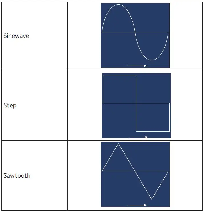
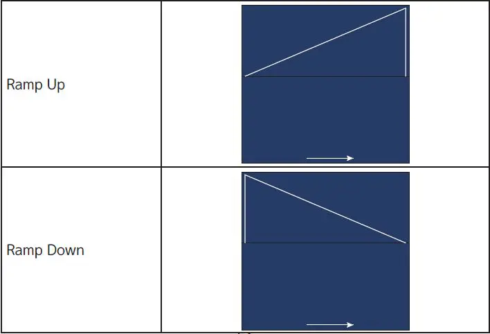
DIMMER CURVES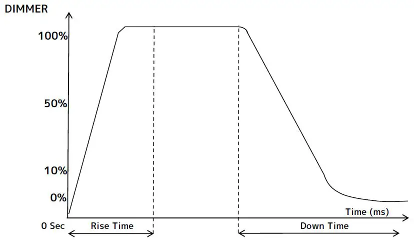
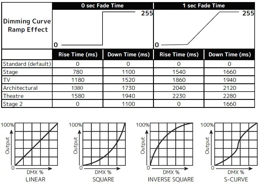
COLOR TEMPERATURE TABLE
| COLOR TEMPERATURE (K) | DMX VALUE | COLOR TEMPERATURE (K) | DMX VALUE | |
| 2000 | 011 | 4150 | 054 | |
| 2050 | 012 | 4200 | 055 | |
| 2100 | 013 | 4250 | 056 | |
| 2150 | 014 | 4300 | 057 | |
| 2200 | 015 | 4350 | 058 | |
| 2250 | 016 | 4400 | 059 | |
| 2300 | 017 | 4450 | 060 | |
| 2350 | 018 | 4500 | 061 | |
| 2400 | 019 | 4550 | 062 | |
| 2450 | 020 | 4600 | 063 | |
| 2500 | 021 | 4650 | 064 | |
| 2550 | 022 | 4700 | 065 | |
| 2600 | 023 | 4750 | 066 | |
| 2650 | 024 | 4800 | 067 | |
| 2700 | 025 | 4850 | 068 | |
| 2750 | 026 | 4900 | 069 | |
| 2800 | 027 | 4950 | 070 | |
| 2850 | 028 | 5000 | 071 | |
| 2900 | 029 | 5050 | 072 | |
| 2950 | 030 | 5100 | 073 | |
| 3000 | 031 | 5150 | 074 | |
| 3050 | 032 | 5200 | 075 | |
| 3100 | 033 | 5250 | 076 | |
| 3150 | 034 | 5300 | 077 | |
| 3200 | 035 | 5350 | 078 | |
| 3250 | 036 | 5400 | 079 | |
| 3300 | 037 | 5450 | 080 | |
| 3350 | 038 | 5500 | 081 | |
| 3400 | 039 | 5550 | 082 | |
| 3450 | 040 | 5600 | 083 | |
| 3500 | 041 | 5650 | 084 | |
| 3550 | 042 | 5700 | 085 | |
| 3600 | 043 | 5750 | 086 | |
| 3650 | 044 | 5800 | 087 | |
| 3700 | 045 | 5850 | 088 | |
| 3750 | 046 | 5900 | 089 | |
| 3800 | 047 | 5950 | 090 | |
| 3850 | 048 | 6000 | 091 | |
| 3900 | 049 | 6050 | 092 | |
| 3950 | 050 | 6100 | 093 | |
| 4000 | 051 | 6150 | 094 | |
| 4050 | 052 | 6200 | 095 | |
| 4100 | 053 | 6250 | 096 |
| COLOR TEMPERATURE (K) | DMX VALUE | COLOR TEMPERATURE (K) | DMX VALUE | |
| 6300 | 097 | 8450 | 140 | |
| 6350 | 098 | 8500 | 141 | |
| 6400 | 099 | 8550 | 142 | |
| 6450 | 100 | 8600 | 143 | |
| 6500 | 101 | 8650 | 144 | |
| 6550 | 102 | 8700 | 145 | |
| 6600 | 103 | 8750 | 146 | |
| 6650 | 104 | 8800 | 147 | |
| 6700 | 105 | 8850 | 148 | |
| 6750 | 106 | 8900 | 149 | |
| 6800 | 107 | 8950 | 150 | |
| 6850 | 108 | 9000 | 151 | |
| 6900 | 109 | 9050 | 152 | |
| 6950 | 110 | 9100 | 153 | |
| 7000 | 111 | 9150 | 154 | |
| 7050 | 112 | 9200 | 155 | |
| 7100 | 113 | 9250 | 156 | |
| 7150 | 114 | 9300 | 157 | |
| 7200 | 115 | 9350 | 158 | |
| 7250 | 116 | 9400 | 159 | |
| 7300 | 117 | 9450 | 160 | |
| 7350 | 118 | 9500 | 161 | |
| 7400 | 119 | 9550 | 162 | |
| 7450 | 120 | 9600 | 163 | |
| 7500 | 121 | 9650 | 164 | |
| 7550 | 122 | 9700 | 165 | |
| 7600 | 123 | 9750 | 166 | |
| 7650 | 124 | 9800 | 167 | |
| 7700 | 125 | 9850 | 168 | |
| 7750 | 126 | 9900 | 169 | |
| 7800 | 127 | 9950 | 170 | |
| 7850 | 128 | 10000 | 171 | |
| 7900 | 129 | |||
| 7950 | 130 | |||
| 8000 | 131 | |||
| 8050 | 132 | |||
| 8100 | 133 | |||
| 8150 | 134 | |||
| 8200 | 135 | |||
| 8250 | 136 | |||
| 8300 | 137 | |||
| 8350 | 138 | |||
| 8400 | 139 | |||
PRIMARY-SECONDARY SET UP
This function allows you to link units together to run in a Primary-Secondary set-up, in which one unit will act as the controlling unit and the others will react to the controlling unit’s built-in programs. Any unit can be configured to act as a Primary or as a Secondary, but only one unit in a given system can be programmed to act as the Primary.
PRIMARY-SECONDARY CONNECTIONS AND SETTINGS:
- Daisy chain your units via the XLR connectors on the rear panels of each unit. Use standard XLR data cables to link your units together. Remember that the male XLR connector is the input and the female XLR connector is the ouput. The first unit in the chain (primary) will use the female XLR connector only, while the last unit in the chain will use the male XLR connector only.
- On the primary unit, use the display screen and control panel to navigate to Function > Auto Program, then use scroll to “Primary” and press ENTER.
- On the secondary unit(s), use the display screen and control panel to navigate to Function > Secondary Mode, and select one of the three available secondary groupings. Please refer to the Record Controller section of this manual for more information regarding secondary mode groupings.
- Repeat Step 3 for each secondary unit in the system. Make sure that only one unit is designated as the Primary, while all other units are designated as Secondaries.
- The secondary units will now follow the behavior of the primary unit.
ERROR CODES
When the unit is powered on, it will automatically enter a “Reset/Test” mode, which brings all the internal motors to a home position. If an internal problem with one or more of the motors is detected, an error code will flash in the display in the form of “XXer” where XX will represent a code associated with the detected error. These codes are listed in the table below. For example, when the display shows “PAN Er” it means there is some type of error with the Pan motor. If there are multiple errors during the start-up process, they will all flash in the display. For example: if the fixtures has errors related to pan, tilt, and zoom all at the same time, you will see the error message “PAN Er”, “TILT Er”, and “Zoom Er” flash and repeat 5 times. If an error is detected during the initial start-up procedure, the fixture will self-generate a second reset signal and try to realign all the motors and correct the errors. If the error persists after a second attempt, a third attempt will be made. If after a third attempt all the errors have not been corrected the fixture will make the following determinations:
- 3 or More Errors: The fixture cannot function properly with three or more errors, and therefore the fixture will place itself in stand-by mode until subsequent repairs can be made.
- Less Than 3 Errors: The fixture has less than 3 errors. Most other functions will work properly. The fixture will attempt to operate normally until the errors can be corrected by a technician. The errors in question will remain flashing in the display as a reminder of internal errors.
| ERROR CODES Error codes are subject to change without any prior written notice. | |
| ERROR CODE | DESCRIPTION |
| PAN Er | Movement is not located in the default position after the reset. This message will appear after a fixture reset if the magnetic-indexing circuit malfunctions (sensor failed, or magnet is missing) or there is a motor failure (defective motor or a defective motor IC drive on the main PCB). This error may also be displayed if the head/yoke was blocked during TILT Er a reset function. |
| TILT Er | |
| Zoom Er | Movement is not located in the default position after the reset. This message will appear after a fixture reset if the magnetic-indexing circuit malfunctions (sensor failed, or magnet is missing) or there is a motor failure (defective motor or a defective motor IC drive on the main PCB). |
SOFTWARE UPDATE
ONLY QUALIFIED TECHNICIANS SHOULD PERFORM THIS FUNCTION! NOTE ALL MENU SETTINGS BEFORE UPDATING SOFTWARE! FIXTURE SOFTWARE CAN NOT BE DOWNGRADED! DOWNLOAD FIXTURE SOFTWARE TO PC ONLY! (NO MAC SUPPORT) PLEASE CONTACT ELATION SERVICE FOR FURTHER INFORMATION.
An Elation E-Loader III can be used to update the fixture to the latest software. Please visit the E-Loader III product page at the Elation web site and download the product manual for step-by-step instructions.
https://www.elationlighting.com/e-loader-iii-software-uploader To order the E-Loader III uploader and the updated software for your fixture, please contact Elation support for details.
DIMENSIONAL DRAWINGS
FIXTURE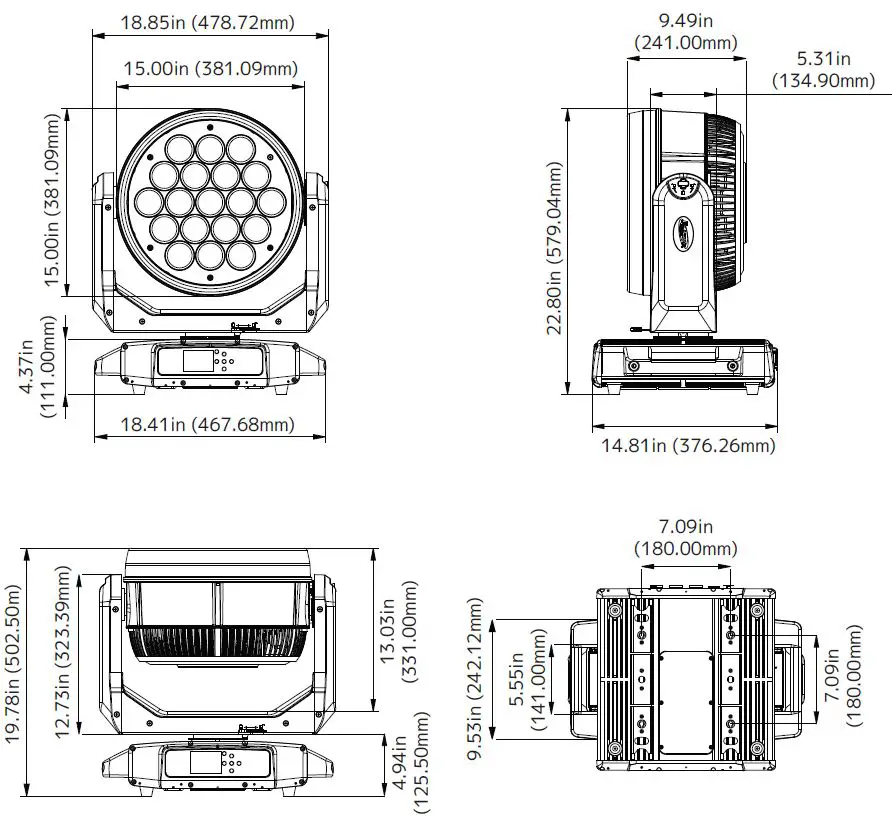
FOAM IN-LAY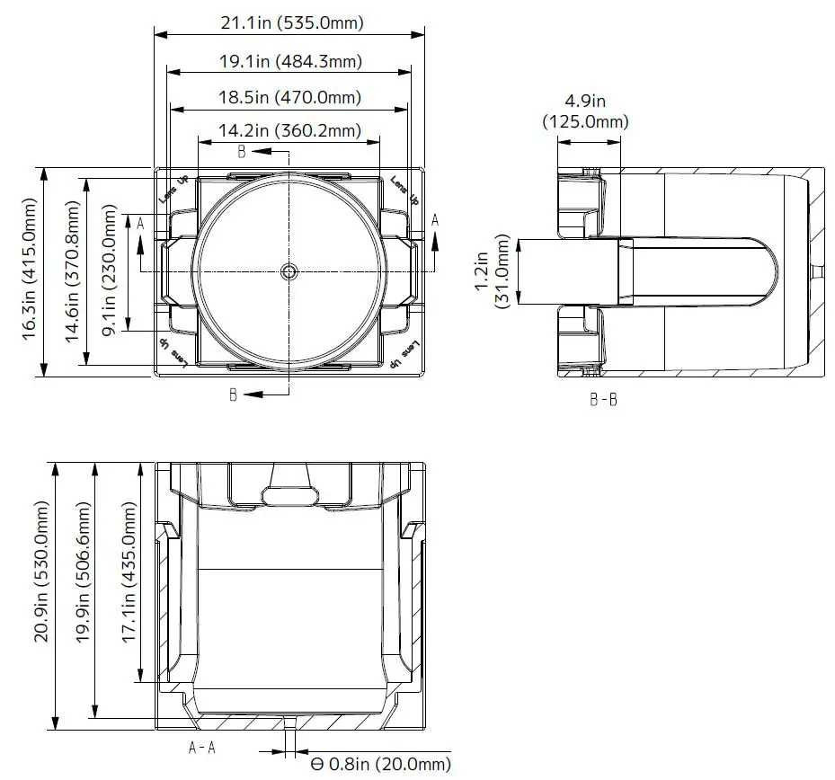
SPECIFICATIONS
- SOURCE
- (19) 60W Osram RGBW LEDs
- (76) 2W White SparkLED™
- 50,000 Hour Average LED Life*
- *Test lab conditions. May vary depending on several factors including but not limited to: Environmental Conditions, Power/Voltage, Usage Patterns (On-Off Cycling), Control, and Dimming.
- PHOTOMETRIC DATA
- 17.000 Total Lumen Output
- CRI 80
- Zoom Range 5.6° – 44°
- EFFECTS
- Motorized Zoom
- Linear Color Temperature Presets (2700-8000K)
- RGBW Color Mixing and Pixel Control
- White SparkLED Lens Effect
- Color Presets and Macros
- Electronic Strobe and Variable Dimming Curves 16-bit Dimming
- Pan Angle: 360° (continuous rotation) / 540°
- Tilt Angle: 360° (continuous rotation) / 270°
- CONTROL / CONNECTIONS
- 3 DMX Channel Modes (25 / 100 / 176 channels)
- 360° Continuous Pan and Tilt Movement
- DMX Adjustable Refresh Rate (900 -25000 Hz) (6) Button Touch Panel
- Full Color 180° Reversible LCD Menu Display
- RDM Support
- IP65 5pin XLR DMX In/Out
- IP65 RJ45 Ethernet In/Out (Art-Net, sACN)
- IP65 Locking Power Cable In
- SIZE / WEIGHT
- Length: 14.81 in (376.26mm)
- Width: 18.41 in (467.68mm)
- Height: 22.80 in (579.04mm)
- Weight: 41.0 lbs. (30kg)
- ELECTRICAL / THERMAL
- AC 100-240V 50/60Hz
- 1400W Max Power Consumption
- APPROVALS / RATINGS CE | cETLus | IP65
FCC STATEMENT
This device complies with Part 15 of the FCC rules. Operation is subject to the following two conditions: (1) this device may not cause harmful interference, and (2) this device must accept any interference received, including interference that may cause undesired operation.
FCC RADIO FREQUENCY INTERFERENCE WARNINGS & INSTRUCTIONS
This equipment has been tested and found to comply with the limits for a class B digital device, pursuant to part 15 of the FCC Rules. These limits are designed to provide reasonable protection against harmful interference in a residential installation. This device uses and can radiate radio frequency energy, and if not installed and used in accordance with the included instructions, may cause harmful interference to radio communications. However, there is no guarantee that interference will not occur in a particular installation. If this device does cause harmful interference to radio or television reception, which can be determined by turning the device off and on, the user is encouraged to try to correct the interference by one or more of the following methods:
- Reorient or relocate that device.
- Increase the separation between the device and the receiver.
- Connect the device and the radio receiver to electrical outlets on separate circuits.
- Consult the dealer or an experienced radio/TV technician for help.
Please note that the changes or modifications of this product that are not expressly approved by the party responsible for compliance could void the user’s authority to operate the equipment.
©2022 ELATION PROFESSIONAL all rights reserved. Information, specifications, diagrams, images, and instructions herein are subject to change without notice. ELATION PROFESSIONAL logo and identifying product names and numbers herein are trademarks of ELATION PROFESSIONAL. Copyright protection claimed includes all forms and matters of copyrightable materials and information now allowed by statutory or judicial law or hereinafter granted. Product names used in this document may be trademarks or registered trademarks of their respective companies and are hereby acknowledged. All non-ELATION brands and product names are trademarks or registered trademarks of their respective companies.
ELATION PROFESSIONAL and all affiliated companies hereby disclaim any and all liabilities for property, equipment, building, and electrical damages, injuries to any persons, and direct or indirect economic loss associated with the use or reliance of any information contained within this document, and/or as a result of the improper, unsafe, insufficient and negligent assembly, installation, rigging, and operation of this product.
Elation Professional USA | 6122 S. Eastern Ave. | Los Angeles, CA. 90040
323-582-3322 | 323-832-9142 fax | www.elationlighting.com | [email protected]
Elation Professional B.V. | Junostraat 2 | 6468 EW Kerkrade, The Netherlands
+31 45 546 85 66 | +31 45 546 85 96 fax | www.elationlighting.eu | [email protected]
Elation Professional Mexico
AV Santa Ana 30 | Parque Industrial Lerma, Lerma, Mexico 52000 +52 (728) 282-7070
DOCUMENT VERSION
Due to additional product features and/or enhancements, an updated version of this document may be available online. Please check www.elationlighting.com for the latest revision/update of this manual before beginning installation and/or programming.
| Date | Document Version | Software Version | DMX Channels | Notes |
| 09/08/2022 | 1.0 | 2.0.0 | 25 / 100 / 176 ch. | Initial Release |
References
 Topics | Elation Lighting Forums
 Home page
-
Elation Professional - Professional Lighting Products
-
Elation Professional EUROPE - Professional Lighting Products
-
Internet Group Management Protocol - Wikipedia
-
Topics | Elation Lighting Forums
-
Home page
-
3.7V 700MA BATTERY FOR PROTEUS LUCIUS
-
E-LOADER III Software Uploader | ELO601


