![]() MC Series Servo Motor Driver
MC Series Servo Motor Driver
User Manual
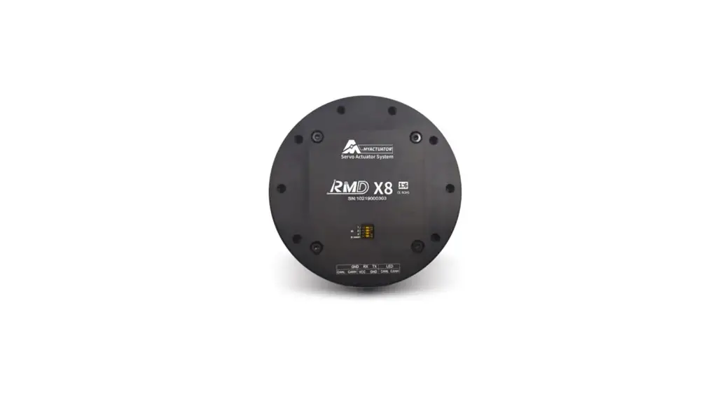
MC Series Servo Motor Driver
The MC series driver is a new generation of high-performance brushless servo driver launched by MyActuator, which can be widely used to drive various BLDC/PMSM motors. This series is MyActuator Intelligent based on years of low-voltage DC servo market experience and combined Various types of customer demand feedback. The drive includes various features, such as: power-off memory to realize data recording under power-off conditions; bus current sampling: real-time knowledge of the current- torque relationship and precise control of the torque output. At the same time, we match the friendly visual graphical interface for the new driver, which is convenient for users to quickly familiar with the product features. For more product information and user experience, please contact your dedicated technical consultant.
Driver Hardware Description
1.1 Schematic Diagram of Size and Interface
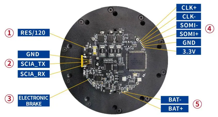
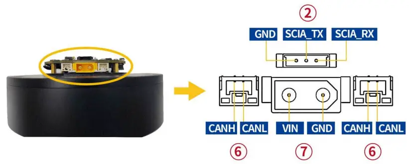
1.2 Interface Definition
| Serial Number | Interface Name | Annotation | Connector Type |
| 1 | Terminating Resistor | 1200 | 2.0 Pitch Pin Header |
| 2 | Debug Serial Port | Level Range: 0-3.3v | 51146-1.25mm-3P ( molex) |
| 3 | Brake Interface | No positive or negative, 24v brake is recommended | Passing Hole Pad |
| 4 | Second Encoder Interface | Interface Protocol: 551 | Pad |
| 5 | External Battery Interface | 1.5-4.2V (1S lipo) | Pad |
| 6 | CAN bus | Level range: 0-3.3v | SMO2-GHS-TB (JST) |
| 7 | Power Supply Port | Voltage range: DC24-48V | XT-30U-F ( AMASSX) |
Driver Parameters
| MC300A | Operating Voltage | 24-48V |
| Rated Current | 5A | |
| Rated Power | 300W | |
| Maximum Instantaneous Current | 10A(30S) | |
| Control Mode Frequency | Torque Mode: 15KHZ | |
| Speed Mode: 5KHZ | ||
| Position Mode:500HZ | ||
| Mos Switching Frequency | 15KHZ | |
| Encoder Resolution | 16bit ( Valid ) | |
| Communication | CAN BUS :1M bps |
The Main Function List of Driver
| Serial Number | Function Name |
| 1. | Read and write control loop KP&KI parameters |
| 2. | Read and write motor acceleration |
| 3. | Read and write encoder data |
| Read motor status and errors | |
| 5. | Motor off command |
| 6. | Motor stop command |
| Motor running command | |
| 8. | Torque close loop control |
| 9. | Speed close loop control |
| 10. | Position close loop control |
| 11. | Read input power value |
| 12. | Read Battery voltage |
| 13. | Torque feed forward function (applicable to robotic arm) |
| 14. | System reset command |
| 15. | Brake opening and closing |
| 16. | CAN ID setting and reading |
Control Circuit Connection
4.1 Principle Block Diagram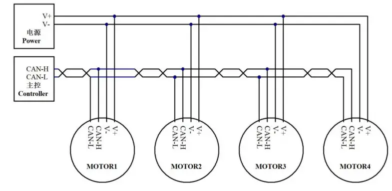
Note: Both ends of the bus need to be connected to 120 ohm terminal resistance
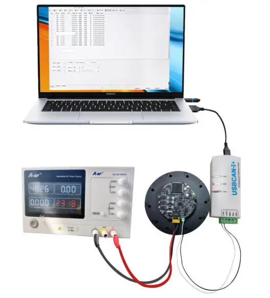
4.2 Schematic Diagram of Physical Connection
Connect via serial port with myactuator GUI 2.1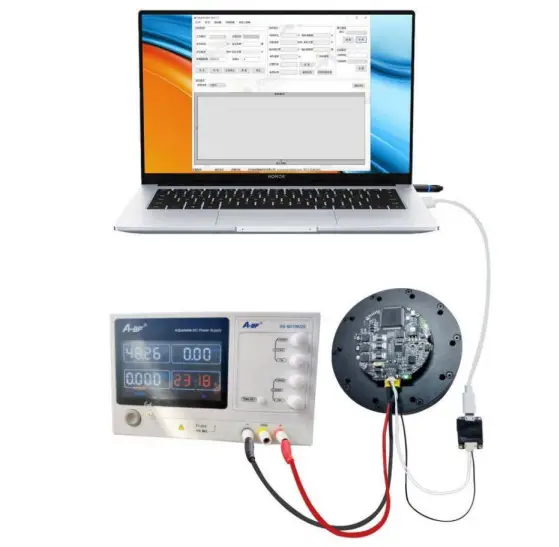
Connect by CAN bus
SUZHOU MYACTUATOR INTELLIGENT TECHNOLOGY CO.. LTD![]() 0512-36863451
0512-36863451![]() www.myactuator.com
www.myactuator.com


