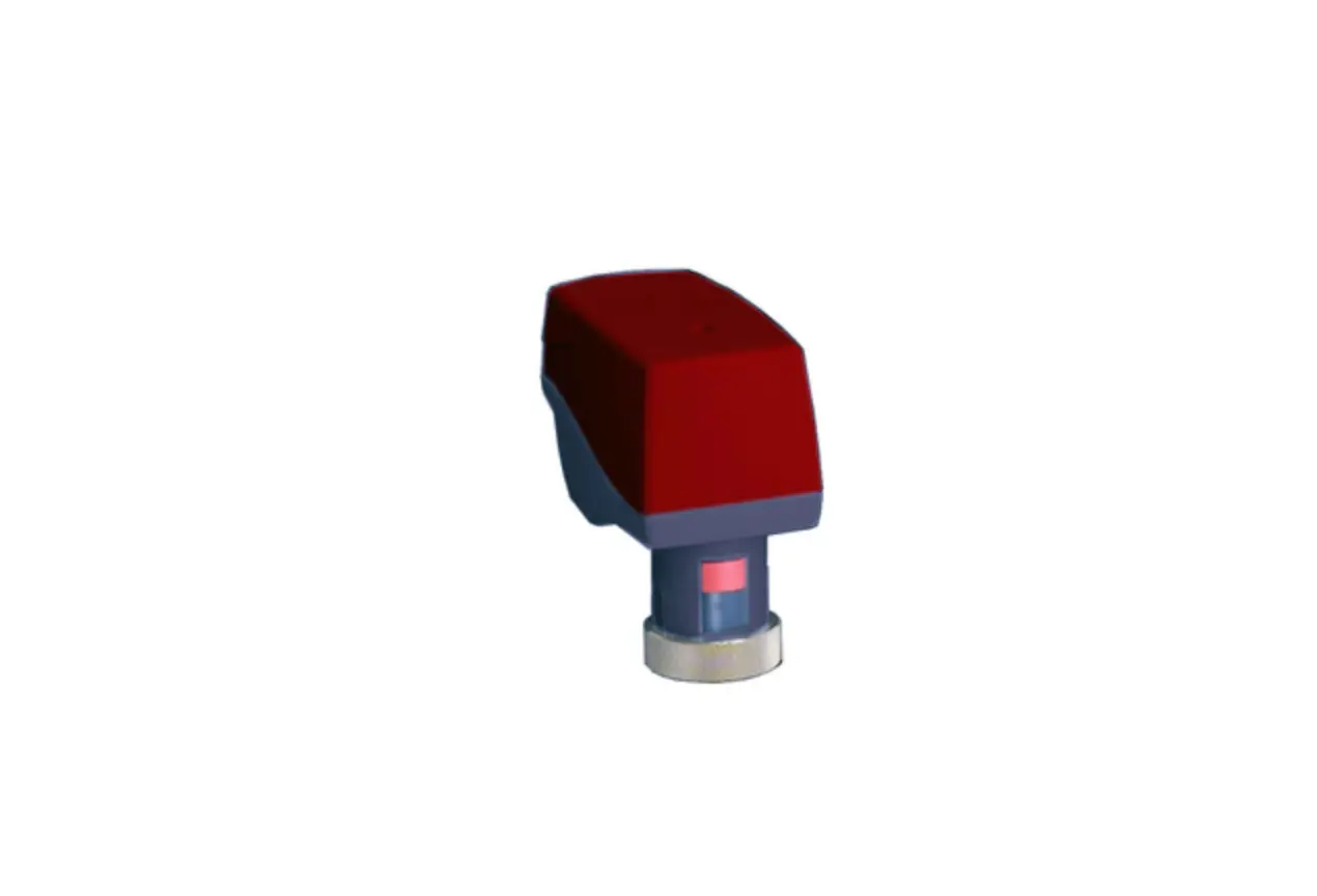
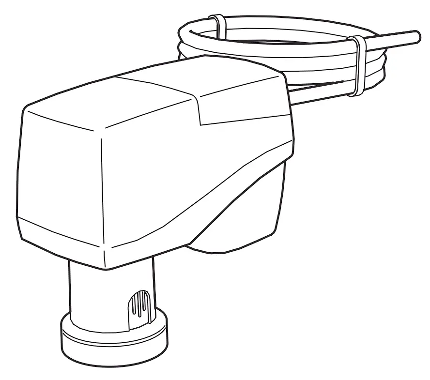
IMI TA MC15 Electrical Linear Actuator
Important Information on Product Safety
Safety instructions
This document contains information on installing and commissioning the product “MC15/24”. Each person who carries out work on this product must have read and understood this document. If you have any questions that are not resolved by this document, you can obtain further information from the supplier or manufacturer.
If the product is not used in accordance with this document, the protection provided could be impaired.
The applicable regulations must be observed when installing and using the devices. Within the EU, these include regulations regarding occupational safety and accident prevention as well as those from the VDE (German Association for Electrical, Electronic & Information Technologies). If the device is used outside of the EU, it is the responsibility of the plant engineer or operator to comply with local regulations.
Mounting, installation and commissioning work on the devices may only be carried out by qualified technicians. Qualified technicians are persons who are familiar with the described product and who can assess given tasks and recognize possible dangers based on their technical training, knowledge and experience, as well as their knowledge of the applicable regulations.
Symbol meanings
 | WARNING Indicates a hazard of medium risk which can result in death or serious bodily injury if not avoided. |
| CAUTION Indicates a hazard of low risk which can result in minor or medium bodily injury if not avoided. |
 | CAUTION Indicates a hazard which can result in material damage or malfunctions if not avoided. |
 | NOTE Indicates additional information that can simplify working with the product. |
Notes on disposal
In accordance with the applicable laws and directives of the European Union countries, the product should not be disposed of with household waste. This ensures environmental protection and sustainable recycling or raw materials.
Commercial users should contact their supplier and observe the conditions of the purchase agreement. This device may not be disposed of together with other commercial waste.
The local and currently applicable laws must be observed.
Item
| MC15/24 | Electrical linear actuator |
Technical Data
| Nominal voltage | AC 24 V ±10%; 50/60 Hz; DC 24 V ±10% |
| Power consumption | Dimensioning: 3.7 VA (AC 24 V); 1.7 W (DC 24 V) Nominal: 2.3 VA (AC 24 V); 1.1 W (DC 24 V) |
| Switch-on current | Max. 4 A for a short time |
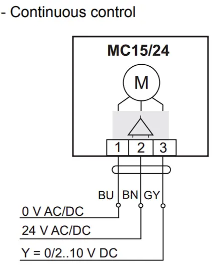
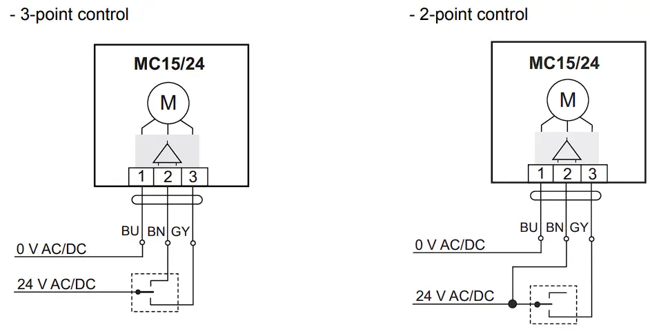
| Contro | Three-point signal (open/stop/close), two-point signal (open/close), min.switch-on time 2 s or continuous control DC 0(2) to 10 V; < 0.5 mA, invertible |
| Connection | fest vormontiertes Kabel 1.5 m; 3 x 0,. mm2 |
| Display | LED display for operating voltage |
| Actuating noise | <28 dB (A) |
| Nominal stroke | max. 9 mm |
| Travel time | 22 s/mm |
| Positioning force | 150 N |
| Position display | Stroke range scale |
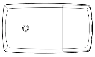
| Manual adjustment | Only when disconnected from the power supply Socket for hexagon key on the actuator cover, key socket 4 mm |
| Valve block protection | Can be switched on |
| Permitted temperatureof medium in valve | 0..120 °C |
| Ambient temperature | During operation: 0..50 °C Out of operation: -20..60 °C |
| Ambient humidity | During operation: 0..85% r.h.; non-condensing Out of operation: 0..85% r.h.; non-condensing |
| Overvoltage category | III |
| Level of contamination | 2 |
| Degree of protection | IP40 |
| Protection class | III |
| Installation position | Anywhere from vertical to horizontal |
| Maintenance | Maintenance-freei |
| Weight | 250 g |
Dimensions
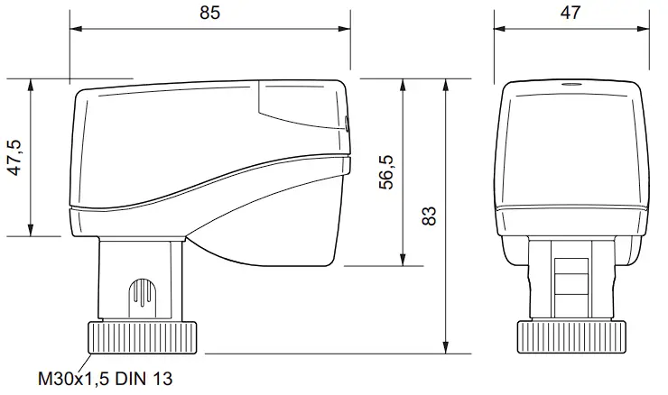
Connection
| CAUTION Temporary peak loads of up to 8 A may occur when switching on the actuator. Ensure suitability ofswitching components (e.g. controller connection) to ensure proper functioning and to avoid malfunctions and damage. |
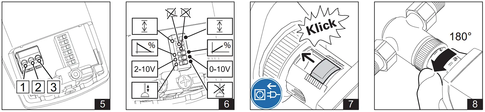
| NOTE The actuation direction can be changed by switching the supply lines to terminals 2 and 3 on the actuator or by setting DIP switch 3. |
Valve Installation
| CAUTION The valve may only be installed by qualified technicians. In addition to the generally applicable installation guidelines, the following items are to be observed: |
- The pipeline system and the interior of the fitting must be free of foreign objects. In the event of contaminated media, dirt collectors are to be inserted upstream of the valves with fine screens, mesh width 0.25 mm.
- There must be no tension between the valve and the pipeline connection.
- To avoid eddy formations in the valve body, the valve should be installed in a straight section of the pipe. A distance of 10 times the nominal diameter is recommended between the valve flange and manifold or other similar parts.
- The installation location is to be selected so that the ambient temperature at the linear actuator is kept between 0 °C and +50°C.
- When carrying out installation, the permissible maximum pressure difference p and the specified direction of flow must be observed.
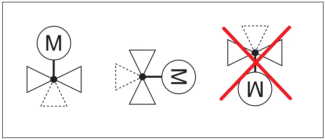
- The three-way valves are to be used as mixing valves. Observe the specified direction of flow.
Once the valve is installed, make sure the ball in the valve seating can be moved easily by pushing in the valve stem. - For safety reasons, do not suspend the linear actuators from under the valve.
- Observe the direction of flow arrow on the valve body. Inverting the direction of flow impairs control behavior.

Installation and commissioning of the linear actuator
| CAUTION Installation and commissioning work may only be carried out by qualified technicians. If the valve is mounted in the plant, make sure that no differential pressure builds up in the valve body before beginning work. If necessary, close the gate valve and turn off pumps. After the pipeline has cooled off, you can begin installing the linear actuator. Be sure to comply with VDE guidelines and local wiring regulations. The device must be connected according to the binding wiring diagram. |
| CAUTION Linear actuator must not be operated electrically without a valve |
Installation
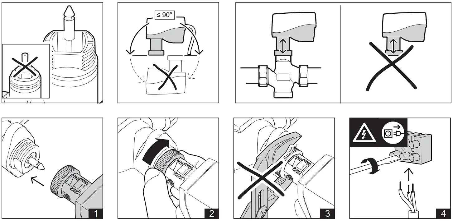
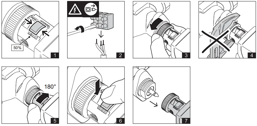
► Place the linear actuator on the threaded connection of the valve and tighten hand-tight using the union nut.
► Establish the electrical connection.
► During initial start-up, an automatic initialization run takes place after switching on the mains and the LED flashes green..
The linear actuator first moves the spindle upwards and then to the lower end position With the valve stem coupled, the actuator then moves to the upper end position of the valve stroke. After completion of the initialization run, the linear actuator follows the control signal and the LED flashes green.
► After completion of the assembly and commissioning work, the automatic coupling must be protected by the dust protection cap (see Fig. 8).
Removing the linear actuator
| CAUTION Before beginning to remove the unit, make sure that no differential pressure builds up in the valve body before beginning work. If necessary, close the gate valve and turn off pumps. After the pipeline has cooled off, you can begin removing the actuator. |
| CAUTION Before beginning to remove the unit, put the actuator in the middle position |
► Move the actuator to the center position using a control signal.
► Disconnect the actuator from the line power. Then disconnect all electrical connections.
► Loosen the union nut.
► Turn the dust cover far enough so that you can press the safety button.
► Press the safety button on the automatic coupling all the way in and hold it (see Fig. 6).
► Remove the actuator from the valve.
Manual adjustment
| CAUTION Before beginning to remove the unit, put the actuator in the middle position |
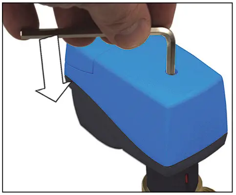
■ The linear actuator must be disconnected from the mains power supply for manual operation.
■ A hexagon key (key socket 4 mm) can be used to move the linear actuator into any position.
| CAUTION If you manually adjust until the slip clutch responds, turn the hexagon key half a turn in the opposite direction after the manually set stroke position has been reached. |
| NOTE An initialization run must be performed after a manual adjustment. This occurs during operation when a valve end position is reached as part of normal operation. You can perform this initialization manually by activating switch 6, see p. 11. |
Commissioning
| Function Switch position ON | Schalter (A) | Function Switch position OFF |
| Reinitialization ON->OFF/ OFF ->ON | 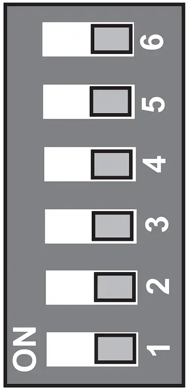 | Reinitialization ON->OFF/ OFF ->ON |
| No function | No function | |
| No function | No function | |
| Actuating direction and position feedback100..0% | Actuating direction and position feedback0..100% | |
| DC 2..10 V | DC 0..10 V | |
| Valve exercise on | Valve exercise off |
Switch 1: Valve block protection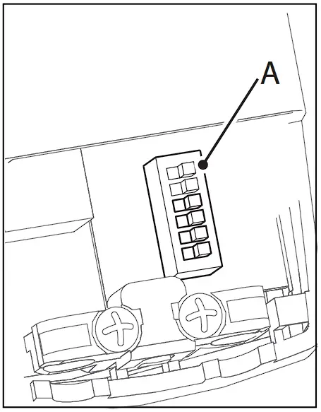
If the plant specifications permit it, the valve block protection can be activated during commissioning.
Block protection prevents the ball from jamming when the valve is not moved for a longer period of inactivity, e.g. for heating systems during the summer.
When the block protection is activated, the valve cone is raised for a few seconds if no stroke movement has occurred in a period of 24 hours.
Factory setting: Off
Switch 2: Setting of the control range by the continuous actuating signal DC 0 V to 10 V or DC 2 V to 10 V\
Factory setting: DC 0 V to 10 V
Switch 3: Setting of the actuating direction with DC 10 V control voltage “valve open![]() “or “valve closed”
“or “valve closed” ![]() and position feedback
and position feedback
Factory setting: 0% to 100%; “valve open”![]()
Switch 6: Reinitialization When the unit is remounted, you must adapt the valves again by performing a reinitialization.
You can do this by changing the switch position of switch 6 from “OFF” to “ON” or from “ON” to “OFF”.
The LED (under the connection cover) flashes green during initialization.
LED states
| LED flashes green in 1s cycle | Initialization is running or initialization was not completed successfully |
| LED lights up green permanently | Initialization was successfully completed, control operation |
| LED lights up red permanently | Blockage, intervention necessary Trigger initialization or briefly interrupt power supply |