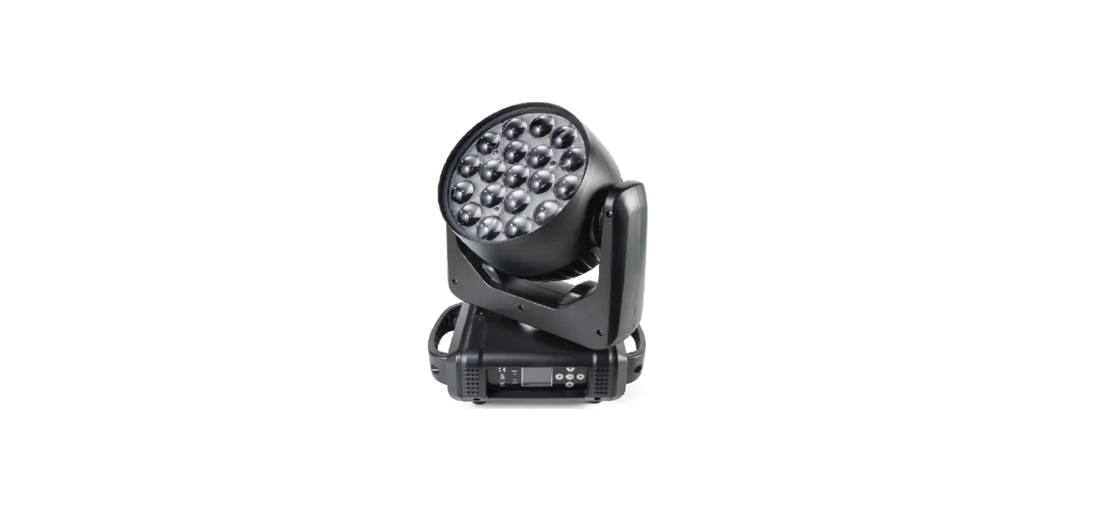
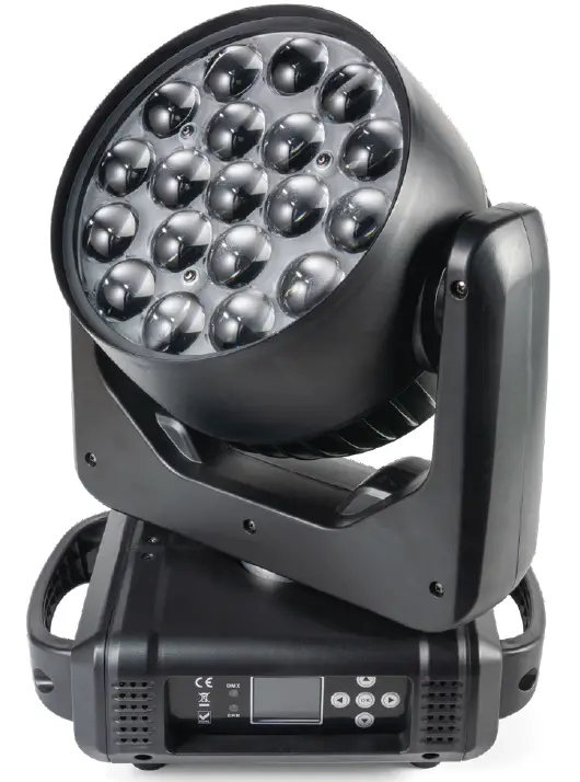
FLASH P7100550 Moving Head 19×15 Zoom
INTRODUCTION
THANK YOU FOR PURCHASING Moving Head 19x15W ZOOM. FOR SAFETY REASONS AND TO ENSURE THE TROUBLE-FREE OPERATION, CAREFULLY READ THE INSTRUCTIONS.
SAFETY INFORMATION
- Please keep this User Manual for future consultation. If you sell the fixture to another user, be sure that they also receive this instruction booklet.
- Unpack and check carefully there is no transportation damage before using the fixture.
- Before operating, ensure that the voltage and frequency of power supply match the power requirements of the fixture.
- It’s important to ground the yellow/green conductor to earth in order to avoid electric shock.
- Disconnect main power before servicing and maintenance.
- Use safety chain when fixes this fixture. Don’t handle the fixture by taking its head only, but always by taking its base.
- Maximum ambient temperature is: 400C.
- Don’t operate it where the temperature is higher than this.
- In the event of serious operating problem, stop using the fixture immediately. Never try to repair the fixture by yourself. Repairs carried out by unskilled people can lead to damage or malfunction. Please contact the nearest authorized technical assistance center. Always use the same type spare parts.
- Do not connect the device to any dimmer pack.
- Do not touch any wire during operation and there might be a hazard of electric shock.
- To prevent or reduce the risk of electrical shock or fire, do not expose the fixture to rain or moisture.
- The housing must be replaced if they are visibly damaged.
- Do not look directly at the LED light spot while the fixture is on.
WARNING
- The Moving Head 19x15W ZOOM has a powerful pan motor. The torque reaction when the head is panned suddenly can cause the base to move if the fixture is standing unsecured on a surface. Do not apply power to the Moving Head 19x15W ZOOM unless the baase is securely fastened to a surface or to rigging hardware.
- Use 2 clamps to rig the fixture. Do not hang the fixture from only one clamp. Lock each clamp with both 1/4-turn fasteners. Fasteners are locked only when turned a full 900 clockwise.
- When clamping the fixture to a truss or other structure at any other angle than with the yoke hanging vertically downwards, use two clamps of half-coupler type. Do not use any type of clamp that does not completely encircle the structure when fastened.
- Position or shade the head so that the front lens will not be exposed to sunlight or any other strong light source from any angle – even for a few seconds. See Figure 2. The Moving Head 19x15W ZOOM lens can focused the sun’s rays, creating a potential fire hazard and causing damage.
IMPORTANT! Do not point strong light output from other fixtures at the Moving Head 19x15W ZOOM, as intense illumination can damaged the display.
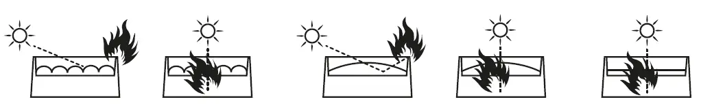
Figure 2. Lenses can focused sunlight and strong light, presenting a risk of fire and damage to the fixture. Shield or shade the head if necessary.
PRODUCT INFORMATION
- Light Source: 19pcs x 15W 4in1 LED
- PAN range: 5400
- TILT range: 2700
- Zoom range: 10-600
- Color: RGBW
- Zoom: Yes
- 16 DMX channel mode.
- 3-Pin XLR DMX input/output
- Power supply: 100-245V AC, 50-60Hz
- Power consumption: 300W
- Net Weight: 7,6 kg
- Weight with packaging: 55 kg (4x Moving Heads + Case)
- Dimensions: H(41 )xW(32)xD(22) cm
- Dim. (case): H(62 )xW(80)xD(52) cm
INSTALLATION
The unit should be mounted via its screw holes on the bracket. Always ensure that the unit is firmly fixed to avoid vibration and slipping while operating. Always ensure that the structure to which you are attaching the unit is secure and is able to support a weight of 10 times of the unit’s weight. Also always use a safety cable that can hold 12 times of the weight of the unit when installing the fixture. The equipment must be fixed by professionals. And it must be fixed at a place where is out of the touch of people and has no one pass by or under it.
CONNECTION
The device is equipped with the following interfaces
- DMX (in/out): XLR 3-pin socket
- Power (in/out): powerCON socket
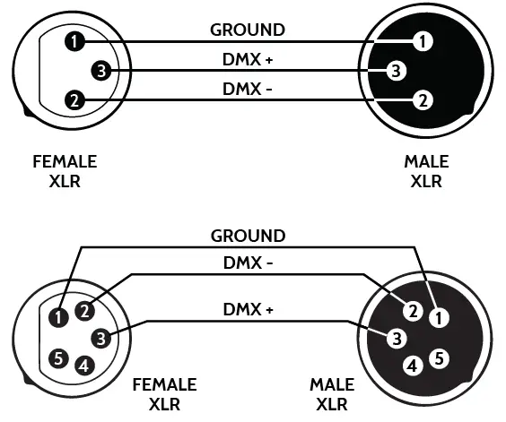
Connecting DMX signal
The connection is performed using cable with XLR-female -> XLR-Male plugs.

CAUTION: At the last fixture, the DMX signal has to be terminated with a terminator. Solder a 120Ω resistor between signal (-) and signal (+) into a XLR plug and plug it in the DMX output of the last fixture.
Voltage specification
| Input Voltage | Total Power | Frequency |
| 100~245V | 300W | 50/60Hz |
Connecting power supply
The connection is performed using power cable with a PowerCon connector (included). The device must be operated by qualified personnel. Make sure that the power grid supply parameters are consistent with device parameters and that limitations are not exceeded.
CAUTION: In the case of cable damage do not attempt to repair. Replacement or repair can be made only on the manufacturer or by a person with appropriate permissions.
Using lamp, the change rate of power voltage should be within ± 10%, if the voltage is too high, it will shorten the light’s life; if it’s not enough, the lamp will be dark. Please restart it after turning off light for 20 minutes until full-cooling. Frequent switching will reduce the life span of lamps and bulbs; intermittent using will improve the life of bulbs and lamps.
SETTING INTERFACE
| Options | Instructions | |
|
System Settings |
DMX address | 001-512 from machine status: receive DMX signal from console or host Press „ok” to enter edit status. At this time, select the hundreds place, press „up” and „down”. The key changes the address code. Click „ok” to select the ten editors again. Click again „Determine” the key to select the individual edit. Press the exit edit status again. |
| The encoder | Start using encoder (optical coupling) to judge the missing step and automatically correct the position Close the correct position without encoder (decoupling) | |
| X inversion | Closed/open | |
| Y inversion | Closed/open | |
| The operation mode | The operation mode | DMX/voice control/automatic |
| Channel selection | 16CH/24CH | |
| Display Settings | Language selection | Chinese, English |
| Pour screen Settings | Shut down | |
|
The factory set up | The X axis calibration | 128 |
| The Y axis calibration | 128 | |
| Focusing calibration | 128 | |
| Red | 220 | |
| Green | 220 | |
| Blue | 220 | |
| White | 220 | |
| Logo to chose | 000 |
DMX CHANNELS
16 CH Mode Setting
| Channel | Function |
| 1 | Pan |
| 2 | Tilt |
| 3 | P/T Speed |
| 4 | Dimmer |
| 5 | Red (R) group 1 |
| 6 | Green (G) group 1 |
| 7 | Blue (B) group 1 |
| 8 | White (W) group 1 |
| 9 | Strobo |
| 10 | Zoom |
| 11 | Function mode |
| 12 | Functional mode speed |
| 13 | Pan Fine |
| 14 | Tilt Fine |
| 15 | Rest(255) |
| 16 | Empty |
24 CH Mode
| Channel | Function |
| 1 | Pan |
| 2 | Tilt |
| 3 | P/T Speed |
| 4 | Dimmer |
| 5 | Red (R) group 1 |
| 6 | Green (G) group 1 |
| 7 | Blue (B) group 1 |
| 8 | White (W) group 1 |
| 9 | Red (R) group 2 |
| 10 | Green (G) group 2 |
| 11 | Blue (B) group 2 |
| 12 | White (W) group 2 |
| 13 | Red (R) group 3 |
| 14 | Green (G) group 3 |
| 15 | Blue (B) group 3 |
| 16 | White (W) group 3 |
| 17 | Strobo |
| 18 | Zoom |
| 19 | Function mode |
| 20 | Functional mode speed |
| 21 | Pan Fine |
| 22 | Tilt Fine |
| 23 | Rest(255) |
| 24 | Empty |


