![]()
Infrastructure
Safety, Operation & Maintenance
DL07 Hydraulic Drill
49234 User Manual 2/2022 Ver. 23
DECLARATION OF CONFORMITY
I. the undersigned:
Nuernberg, David
Surname and First names
hereby declare that the equipment specified hereunder:
- Category:
Drill, Hydraulic - Make
STANLEY - Type
DL0755001, DL0765201 - a serial number of equipment:
All
Has been manufactured in conformity withDirective/Standards No. Approved body EN ISO
EN ISO
EN ISO
EN ISO
EN ISO
EN ISO
EN ISO
Machinery Directive4413:2010
12100:2010
28927-5:2009
3744:2010
11148-3:2012, Cl. 5.4
11148-3-2012, Cl. 5.5
13732-1:2008
2006/42/EC:2006Self
Self
Self
Self
Self
Self
Self
Self - Special Provisions: None
- Representative in the Union: Patrick Vervier, Stanley Dubuis 17-19, rue Jules Berthonneau-BP 3406 41034 Blois Cedex, France.
Done at a Stanley Infrastructure, Milwaukie, Oregon USA Date 4-24-2018
Signature
Position

 |  |
 |  |
 |  |
 |  |
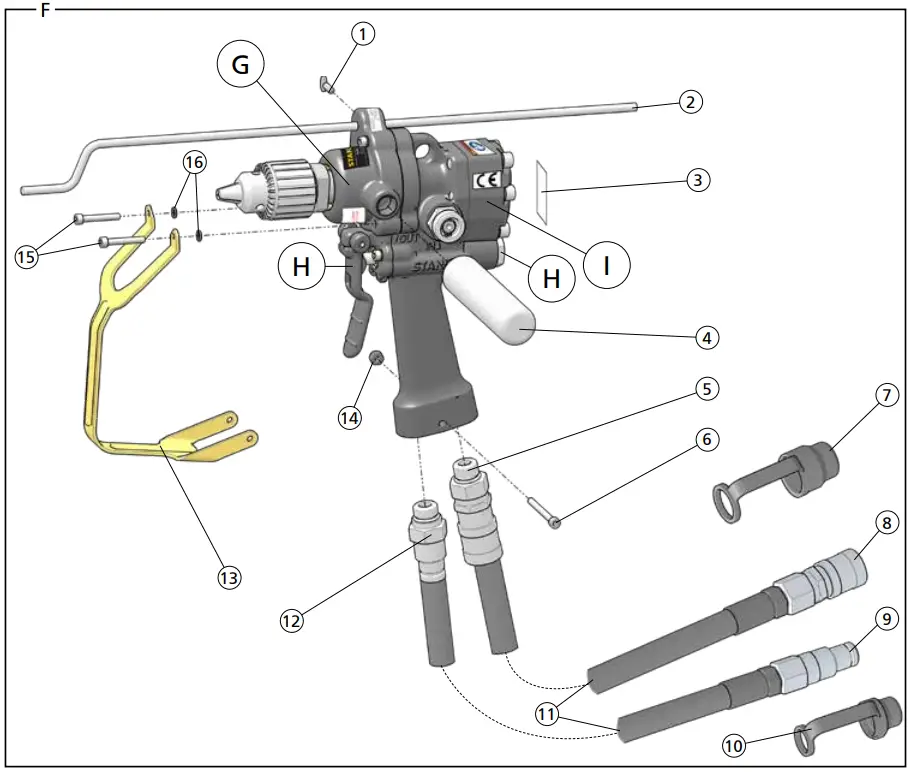
| DL07 Parts Illustration – Detail F | ||
| ITEM | P/N | DESCRIPTION |
| 1 | 38685 | Depth Gauge Screw – Models DL07552B, DL07552M, DL07552S, DL07572B, DL07572S. |
| 2 | 38676 | Depth Gauge – Models DL07552B, DL07552M, DL07552S, DL07572B, DL07572S. |
| 3 | 29149 | Rotation Direction Decal – CE Models |
| 4 | 08130 | Assist Handle |
| 5 | 58856 | Female Coupler – Models DL0755201, DL0765201 |
| 6 | 09687 | Cap Screw |
| 7 | 02324 | Hose Cap – Model DL07552SUP |
| 8 | 03972 | Female Coupler – Models DL07552S, DL07552SUP, DL07572S |
| 9 | 03973 | Male Coupler – Models DL07552S, DL07552SUP, DL07572S |
| 10 | 03288 | Hose Cap – Model DL07552SUP |
| 11 | 56725 | Hose (Parker) |
| 66727 | Hose (Aeroquip) | |
| 12 | 58857 | Male Coupler- Models DL0755201, DL0765201 |
| 13 | 60710 | Trigger Guard |
| 14 | 07724 | Nylock Nut |
| 15 | 62228 | Cap Screw |
| 16 | 09623 | Lockwasher |
| 17 | 60792 | DL07 Seal Kit – Not Shown (*In seal kit) |
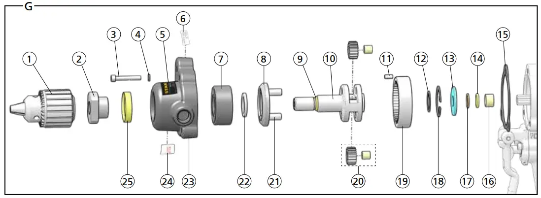
| DL07 Gear Box Illustration – Detail G | ||
| ITEM | P/N | DESCRIPTION |
| 1 | 09624 | 1/2 Inch Chuck |
| 27628 | 5/8 Inch Chuck – Models DL07572B, DL07572S | |
| 2 | 09778 | Seal Nut |
| 3 | 62228 | Cap Screw |
| 4 | 09623 | Lock Washer |
| 5 | 74696 | Tool Name Tag |
| 6 | 29148 | RPM Decal |
| 7 | 08175 | Bearing |
| 8 | 08163 | Bearing Keeper |
| 9 | 00354 | O-Ring* |
| 10 | 09779 | Output Shaft |
| 11 | 00563 | Roll Pin |
| 12 | 08440 | Retaining Ring |
| 13 | 20767 | Seal Back-up Washer |
| 14 | 00354 | O-Ring* |
| 15 | 58635 | Gasket* |
| 16 | 20758 | Bushing |
| 17 | 13995 | Back-up Ring* |
| 18 | 06635 | Retaining Ring |
| 19 | 08166 | Ring Gear |
| 20 | 08165 | Planet Gear Assembly |
| 21 | 08161 | Planet Shaft |
| 22 | 08162 | Shaft Keeper |
| DL07 Gear Box Illustration – Detail G | ||
| ITEM | P/N | DESCRIPTION |
| 23 | 58403 | Gear Housing |
| 24 | 11354 | Open Center / Closed Center Decal |
| 25 | 09621 | Shaft Seal* |
| 26 | 60792 | DL07 Seal Kit – Not Shown (*In seal kit) |
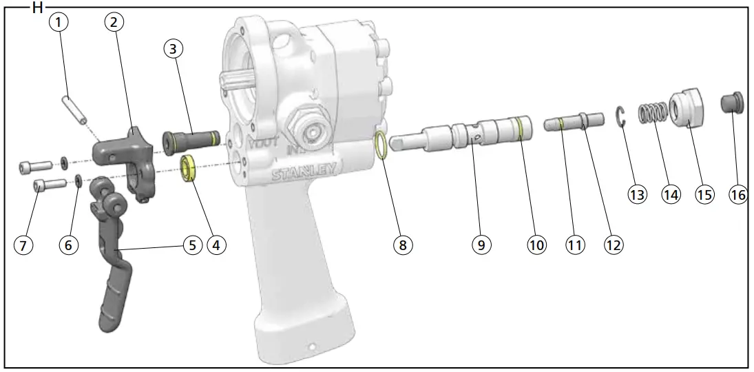
| DL07 Trigger & OC/CC Valve Illustration – Detail H | ||
| ITEM | P/N | DESCRIPTION |
| 1 | 07970 | Roll Pin |
| 2 | 60678 | Trigger Mount Casing |
| 3 | 58462 | Relief Cartridge Plug Assembly |
| 4 | 49139 | Seal Wiper* |
| 5 | 60677 | Trigger |
| 6 | 09623 | Lock Washer |
| 7 | 62229 | Cap Screw |
| 8 | 07627 | O-Ring* |
| 9 | 48986 | Valve Spool Assembly (Includes 00026, 07626, 16070, 48987, 48989, 48990, 49132) |
| 10 | 07626 | O-Ring* |
| 11 | 00026 | O-Ring* |
| 12 | 48986 | Selector Screw (Must be purchased as part of the valve spool assembly) |
| 13 | 16070 | Retaining Ring |
| 14 | 65480 | Spring |
| 15 | 56758 | Spring Cap (Loctite 242) |
| 16 | 350041 | Hex Plug |
| 17 | 60792 | DL07 Seal Kit – Not Shown (*In seal kit) |
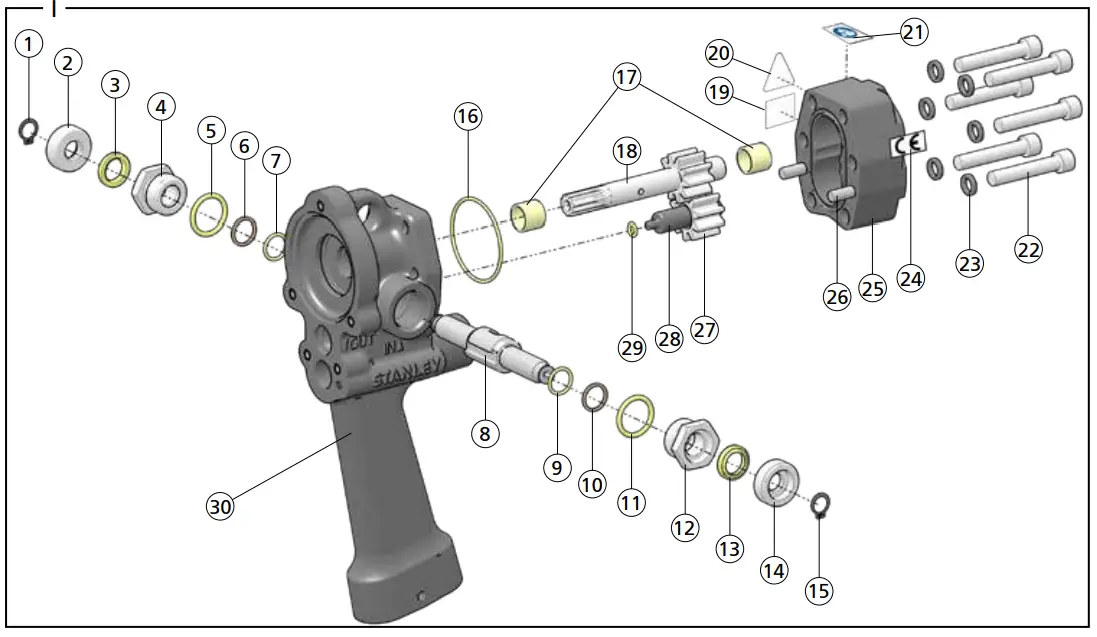
| DL07 Reversing Valve & Hydraulic Motor Illustration – Detail I | ||
| ITEM | P/N | DESCRIPTION |
| 1 | 56764 | Retaining Ring |
| 2 | 56757 | End Cap |
| 3 | 56747 | Seal Wiper* |
| 4 | 56749 | Seal Cap |
| 5 | 01604 | O-Ring* |
| 6 | 07224 | Back-up O-Ring* |
| 7 | 00175 | O-Ring* |
| 8 | 56765 | Reversing Spool |
| 9 | 00175 | O-Ring* |
| 10 | 07224 | Back-up O-Ring* |
| 11 | 01604 | O-Ring* |
| 12 | 56749 | Seal Cap |
| 13 | 56747 | Seal Wiper* |
| 14 | 56757 | End Cap |
| 15 | 56764 | Retaining Ring |
| 16 | 01262 | O-Ring* |
| 17 | 05207 | Bushing |
| 18 | 24271 | Main Shaft |
| 19 | 88451 | Sound Power Decal – Model DL0755201 |
| DL07 Reversing Valve & Hydraulic Motor Illustration – Detail I | ||
| ITEM | P/N | DESCRIPTION |
| 20 | 11207 | Circuit Type “D” Decal (CE Models) |
| 58862 | Pressure Warning (Non-CE Models) | |
| 21 | 88348 | Read the Manual Decal |
| 22 | 18206 | Cap Screw (Torque to 15-17 Ft. Lbs.) |
| 23 | 00231 | Lock Washer |
| 24 | 28323 | CE Decal (CE Models) |
| 58864 | Electrical Warning Decal (Non-CE Models) | |
| 25 | 20770 | Motor Cap Assembly (Includes 1x 05207, 2x 00713) |
| 26 | 00713 | Dowel Pin |
| 27 | 20768 | Idler Gear |
| 28 | 20782 | Idler Shaft |
| 29 | 00026 | O-Ring* |
| 30 | 59049 | Main Housing Assembly |
| 31 | 60792 | DL07 Seal Kit – Not Shown (*In seal kit) |
Safety Precautions
| The Safety Alert Symbol alerts you to potential personal injury hazards. Obey all safety messages that follow to avoid possible injury or death. |
| Indicates an imminently hazardous situation that will result in death or serious injury. | |
| Indicates a potentially hazardous situation that could result in death or serious injury. | |
| Indicates a potentially hazardous situation that could result in property damage. |

Always observe safety symbols. They are included for your safety and for the protection of the tool. WARNING: Read all safety warnings and instructions. Failure to follow warnings and instructions may result in tool damage and/or serious injury.
WARNING: To reduce the risk of injury, read the instruction manual.
General
- Do not discard safety instructions. Give to the operator.
- This tool will provide dependable service if operated in accordance with the instructions given in this manual. Read and understand this manual and any stickers and tags attached to the tool and hoses before operation. Failure to do so could result in personal injury or equipment damage.
- Inspect the tool before each use and ensure all decals are legible. Contact STANLEY if replacements are needed.
- Establish a training program for all operators to ensure safe operation. Do not operate the tool unless thoroughly trained or under the supervision of an instructor. Keep out of the reach of children.
- Operators and maintenance personnel shall be able to physically handle the bulk, weight, and power of the tool.
- Avoid unsuitable postures as these positions do not allow for counteracting of normal or unexpected movement of the tool, such as a sudden break of the tool bit. Change postures during extended tasks to help avoid discomfort or fatigue.
- Do not operate a damaged, improperly adjusted, modified or incompletely assembled tool.
- Do not operate the tool in explosive atmospheres, such as in the presence of flammable liquids, gases or dust. Power tools create sparks that may ignite dust or fumes.
- Provide adequate ventilation in closed areas when operating a gas or diesel hydraulic power source.
- Do not inspect, carry, clean, change accessories or perform maintenance on the tool while the power source is connected. Accidental engagement of the tool can cause serious injury.
- Ensure the workpiece is securely fixed. Be aware that failure of the workpiece or accessories may generate high-velocity projectiles.
- Stay alert, watch what you are doing and use common sense when operating a hydraulic tool. Do not operate this tool if you are tired or under the influence of drugs or alcohol. A moment of inattention while operating hydraulic tools may result in serious injury.
- Assess risks to others around you before operating the tool.
- During operation, do not contact mechanisms, accessories or hardware as they can become very hot; use your Personal Protection Equipment (PPE).
- Use and maintain the tool as stated in this manual. Misuse of this tool is forbidden. Misuse of the tool can cause serious injury. Do not modify the tool in any way.
- Supervising personnel should develop additional precautions relating to the specific work area and local safety regulations.
- Never operate the tool if you cannot be sure that underground utilities are not present, such as electrical cables, gas pipes, etc. These can cause a hazard if damaged with the tool.
- The tool is not insulated against coming into contact with electric power. Use hose certified as non-conductive.
- Do not overreach. Maintain proper footing and balance at all times when using the tool.
- Slips, trips, and falls are major causes of workplace injury. Be observant of hoses lying about the work area, as they can be a tripping hazard.
- Operators must start in a work area without bystanders and must assess the risk to bystanders, including the risk of serious injury or death caused by the tool or accessories dropped from an elevated height.
- Operators must be familiar with all prohibited work areas such as excessive slopes and dangerous terrain conditions.
- Only use clean hydraulic fluid and lubricants that have been recommended by STANLEY.
- Ensure tools are working properly and safely by performing preventative maintenance (PM) procedures.
- Repair and service of this tool must only be performed by an authorized and certified dealer.
- Use only replacement parts recommended by STANLEY.
- Do not force the tool to do the work of a larger tool. Use the correct tool for your application.
- Use only hoses and hose couplings that are rated for a minimum working pressure of 2500 PSI (172 BAR).
- Keep hands away from rotating chuck, drill bits or drives.
- Rotating drive sockets and drive extensions can easily entangle rubber-coated gloves or metal-reinforced gloves. Never hold the drive, sockets, drive extensions, or other accessories.
- Do not use in confined spaces. Beware of crushing hazards between the tool and the workpiece, especially when unscrewing or reversing the tool.
- Keep the work area well lit.
- Prevent unintentional starting. Ensure the trigger is in the off position before connecting to a power source, picking up, or carrying the tool. Carrying power tools with your finger on the trigger or energizing power tools that have the trigger on invites accidents.
- In spite of the application of relevant safety regulations and the implementation of safety devices, certain residual risks cannot be avoided. These risks are repetitive strain injury due to incorrect posture and the risk of pinching fingers when changing tool bit or pressing the trigger.
Dust and Fumes
- WARNING: Some dust created by power sanding, sawing, grinding, drilling, and other construction activities contains chemicals known to the State of California to cause cancer, birth defects, or other reproductive harm. Some examples of these chemicals are:
- Lead from lead-based paints,
- crystalline silica from bricks and cement and other masonry products, and
- arsenic and chromium from chemically treated lumber.
Your risk from these exposures varies, depending on how often you do this type of work. To reduce your exposure to these chemicals: work in a well-ventilated area, and work with approved safety equipment, such as those dust masks that are specially designed to filter out microscopic particles. Protect yourself and those around you. Research and understand the materials you are drilling. Follow correct safety procedures and comply with all applicable national, state, or provisional health and safety regulations relating to them, including if appropriate arranging for the safe disposal of the materials by a qualified person. - When dust or fumes are created, control them at the point of emission. Direct tool exhaust to minimize disturbance of dust.
- Operate and maintain the tool as recommended in this manual to minimize dust.
- Use respiratory protection in accordance with employers’ instructions or as required by occupational health and safety regulations.
- Avoid prolonged contact with dust. Allowing dust to get into your mouth, eyes or lay on the skin may promote the absorption of harmful chemicals.
- Select and replace tool bits as recommended in order to prevent an unnecessary increase in dust or fumes.
- Keep tool handles dry, clean, and free from oil and grease. This will enable better control of the tool.
PPE
- Always wear safety equipment such as impact-resistant goggles, ear protection, head protection, breathing protection, and safety shoes at all times when operating the tool.
- Hands may be exposed to hazards, impacts, cuts, abrasions, and heat. Wear gloves.
- Wear a hardhat if performing overhead work.
- Use PPE that conforms to standards ANSI Z87.1 (Eye and Face Protection), ANSI Z89.1 (Head Protection), ANSI Z41.1 (Foot Protection), and ANSI S12.6 (S3.19) (Hearing Protection).
- Do not wear loose-fitting clothing, jewelry, or gloves with cut or frayed fingers when operating the tool. Entanglement, choking, scalping and laceration can occur if loose clothing, personal jewelry, neckwear, hair, or gloves are not kept away from the rotating tool and its accessories. Gloves can become entangled with the rotation drive, causing severed or broken fingers.

Sound
- Exposure to high noise levels can cause permanent, disabling hearing loss and other problems, such as tinnitus (ringing, buzzing, whistling or humming in the ears). Use hearing protection in accordance with the employer’s instructions and as required by occupational health and safety regulations. Appropriate controls to reduce the risk can include actions such as damping materials to prevent workpieces from “ringing”.
- Use and maintenance as recommended in the manual to prevent an unnecessary increase in noise levels.
Vibration
- When using a rotary or percussive tool to perform work-related activities, the operator can experience discomfort in the hands, arms, shoulders, neck or other parts of the body.
- If you experience numbness, tingling, pain, or whitening of the skin in your fingers or hands, stop using the tool. Tell your employer and consult a physician.
- Wear warm clothing when working in cold conditions and keep your hands warm and dry.
- Exposure to vibration can cause disabling damage to the nerves and blood supply of the hands and arms.
- Do not use worn or ill-fitting sockets or extensions, as this is likely to cause a substantial increase in vibration.
- Do not touch sockets or accessories during impact. This increases the risk of cuts, burns or vibration injuries.
- Use and maintenance as recommended in the manual to prevent an unnecessary increase in vibration.
- Check the vibration level after each service. If higher than normal, contact your STANLEY dealer.
Hydraulic
- Warning: Hydraulic fluid under pressure could cause skin injection injury. Do not check for leaks with your hands. If you are injured by hydraulic fluid, get medical attention immediately.
- Do not let hydraulic oil get on the skin. Hydraulic oil is hot. Wear Personal Protection Equipment (PPE) at all times.
- If exposed to hydraulic fluid, wash hands immediately.
- Do not exceed the maximum relief valve setting stated on the tool.
- Inspect and clean couplers before use, daily. Replace damaged couplers immediately.
- The hydraulic circuit control valve must be OFF before coupling or uncoupling tools. Failure to do so may damage the couplers and cause overheating of the hydraulic system.
- Ensure the couplers are properly connected and are tight.
- Do not operate the tool at fluid temperatures above 140°F (60°C). Higher temperatures can cause operator discomfort and damage to the tool.
- Do not exceed the rated flow and pressure as stated on the tool. Rapid failure of the internal seals may result.
What is the DL07 Hydraulic Drill?
DL07 is a reversible, variable speed drill used for drilling wood, metal and masonry.
| Specifications | ||
| Pressure | 1000-2000 PSI (70-140 BAR) | |
| Flow | 4-12 GPM (15-46 LPM) | |
| Max. Pressure | 2500 PSI (172 BAR) | |
| Max. Relief Pressure | 2100 PSI (145 BAR) | |
| Recommended Back Pressure | 250 PSI (17 BAR) – Can be used with higher back pressures with reduced seal life. | |
| Couplers | 3/8 Inch, NPT Male Adapter | |
| Port Size | -8 SAE O-Ring | |
| Tool Weight | 8 Lbs. (3.6 Kg) | |
| Tool Size | 9 Inches x 9 Inches x 12.8 Inches | |
| Max. Hydraulic Oil Temperature | 140°F (60°C) | |
| HTMA/EHTMA Category | Type I, II & III – Category D | |
| Underwater Tool Max. Depth | 1000 Feet (305 M) | |
| Recommended Hose Diameters for Underwater Applications | ||
| Depth | 8 GPM (30 LPM) | 12 GPM (45 LPM) |
| 100 Feet (31 Meters) | 5/8 Inches (16 mm) | 5/8 Inches (16 mm) |
| 300 Feet (91 Meters) | 3/4 Inches (19 mm) | 1 Inch (25.4 mm) |
| 600 Feet (183 Meters) | 1 Inch (25.4 mm) | 1 Inch (25.4 mm) |
| 1000 Feet (305 Meters) | 1 Inch (25.4 mm) | 1 1/4 Inches (32 mm) |
| Torque and Drill Speeds @ Flow | ||
| 3 GPM (11.3 LPM) | 4 Ft. Lbs. @ 500 PSI – 350 RPM (5.4 Nm @ 35 BAR) | |
| 4 GPM (15 LPM) | 9 Ft. Lbs. @ 1000 PSI – 475 RPM (12.2 Nm @ 70 BAR) | |
| 6 GPM (23 LPM) | 14 Ft. Lbs. @ 1500 PSI – 750 RPM (19 NM @ 105 BAR) | |
| 8 GPM (30 LPM | 19 Ft. Lbs. @ 2000 PSI – 1000 RPM (25.7 Nm @ 140 BAR) | |
| 10 GPM (38 LPM) | 19 Ft. Lbs. @ 2000 PSI – 1250 RPM (25.7 Nm @ 140 BAR) | |
| Sound & Vibration Declaration | |
| Measured A-Weighted sound power level | 85.92 dBA |
| Uncertainty | 3.39 dBA |
| Measured A-Weighted Sound Pressure | 77.93 dBA |
| Uncertainty | 3.39 dBA |
| Values are determined according to the noise test code given in ISO 15744, 11203 and 3744. Test conducted by an independent notified body to comply with 2000/14/EC:2005. | |
| Declared vibration emission value in accordance with EN12096. | |
| Measured Vibration Emission Value: Trigger Handle | 1.8 m/sec² |
| Measured Vibration Emission Value: Assist Handle | 2.5 m/sec² |
| Uncertainty | 0.73 m/sec² |
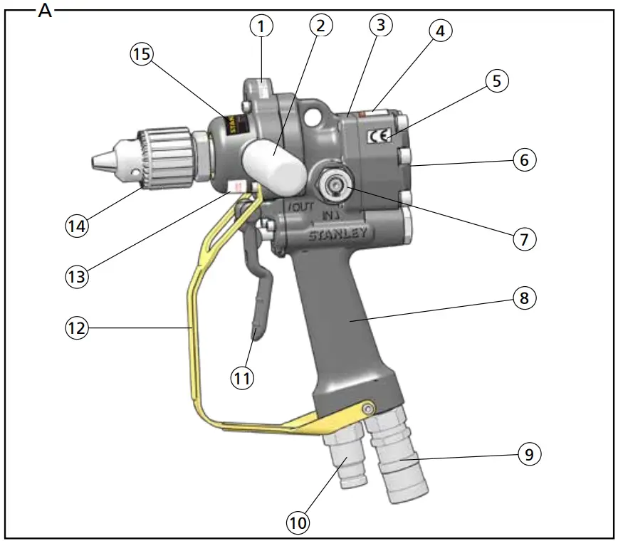
Parts of a DL07 – Detail A
| 1 | RPM Decal |
| 2 | Assist Handle |
| 3 | Serial Number & Year of Manufacture |
| 4 | Read the Manual Decal (CE Models) |
| 5 | CE Decal (CE Models) |
| Electrical Warning Decal (Non-CE Models) | |
| 6 | Rotation Direction Decal |
| 7 | Rotation Direction Spool |
| 8 | Handle |
| 9 | Female Hydraulic Coupler |
| 10 | Male Hydraulic Coupler |
| 11 | Trigger |
| 12 | Trigger Guard |
| 13 | Open Center / Closed Center Decal |
| 14 | Drill Chuck |
| 15 | Tool Name Tag |
Tool Setup
![]()
Do not install or change tool accessories while the hydraulic power source is connected. Accidental engagement of the tool can cause serious injury. Disconnect the hydraulic power source before installing or changing accessories.
- Disconnect the tool from the hydraulic power source.
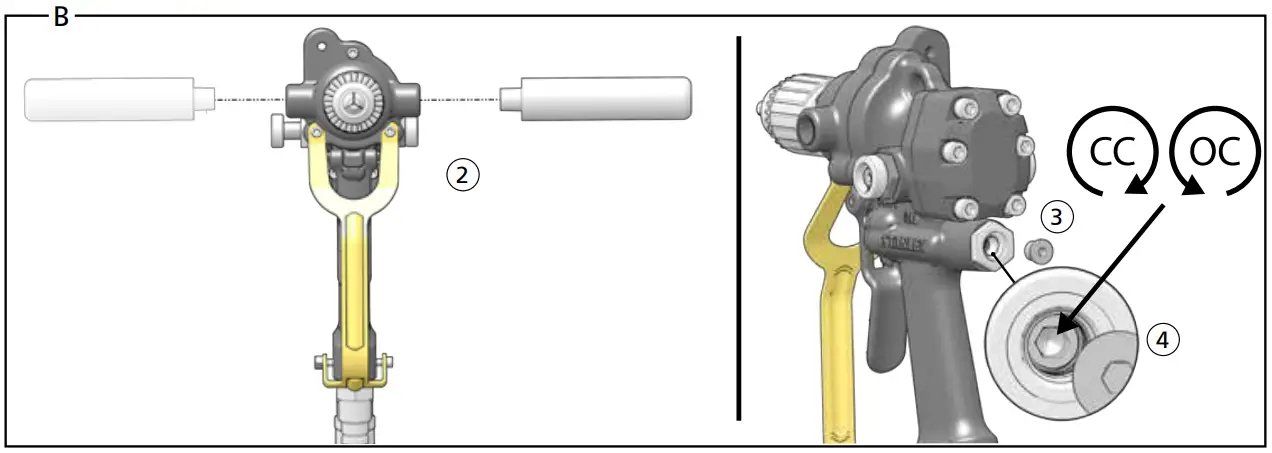
Install Assist Handle & Set Hydraulic Circuit Type – Detail B
The assist handle helps to absorb reaction torque and control the tool. Loss of control can cause personal injury. STANLEY recommends you use the assist
handle whenever possible. - Screw the assist handle into the drill body.
Note: The assist handle is held with your non-dominant hand. - Remove the hex plug on the back of the tool handle.
- Turn the selector screw completely clockwise for open center operation
-OR- completely counterclockwise for closed center operation. - Reinstall the hex plug.
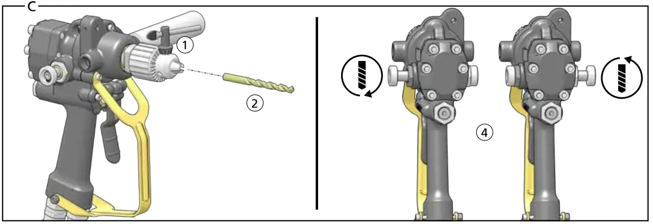
Insert Bit & Choose Drill Rotation Direction – Detail C
- Open the drill chuck using the chuck key.
- Insert the bit, center it and tighten the chuck.
Note: Never operate the tool unless the inserted bit is retained. Bit can become a high-velocity projectile. Secure the bit by tightening the chuck. - Store the chuck key away from the drill.
 Do not operate the tool with the chuck key inserted into the chuck. A chuck key left attached to a rotating part of the tool may result in personal injury.
 - Push the rotation direction spool left for clockwise bit rotation -OR- right for counterclockwise bit rotation.
Tool Operation
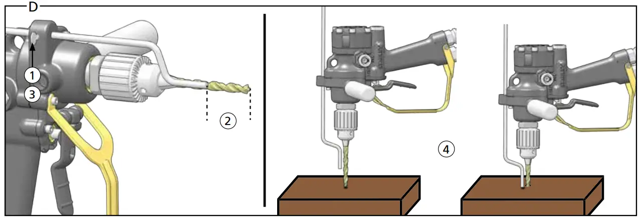
Set Depth Gauge – Detail D
Note: The depth gauge is included with Models DL07552B, DL07552M,
DL07552S, DL07572B & DL07572S.![]() Do not set or reset the depth gauge if the hydraulic power source is connected. Accidental engagement of the tool can cause serious injury. Disconnect the hydraulic power source before setting or resetting accessories.
Do not set or reset the depth gauge if the hydraulic power source is connected. Accidental engagement of the tool can cause serious injury. Disconnect the hydraulic power source before setting or resetting accessories.
- Loosen the depth gauge thumb screw.
- Slide the depth gauge rod so that the distance between the rod tip and the bit tip is equal to your drilling depth.
- Tighten the thumb screw.
- When drilling, the depth gauge will contact the material being drilled, stopping the bit from progressing further.
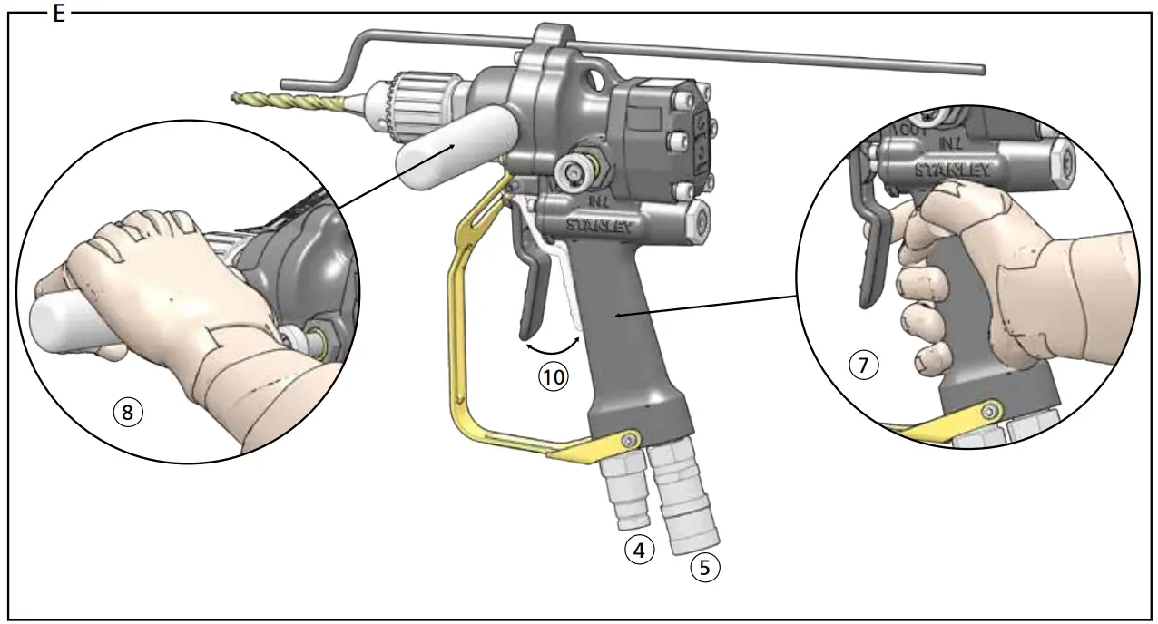
Connect to a Hydraulic Power Source – Detail E
- Using a calibrated flow and pressure gauge, check the output of the hydraulic power source. Ensure it matches the flow and pressure in “Specifications” on page 9. The hydraulic fluid must be 50°F or above. Preheat if necessary.
Note: Check the hydraulic power source once a day. Proper flow and pressure is critical to maintaining proper tool speed. - Ensure that the hydraulic power source is equipped with a relief valve set to open at the maximum relief pressure, see “Specifications” on page 9.
- Wipe hose couplers with a clean, lint-free cloth.
- Connect the return hose to the tool port marked “Out”.
- Connect the pressure hose to the tool port marked “In”.
- Ensure all hydraulic connections are tight.
Using the Tool – Detail E - Hold the main tool handle with your dominant hand.
- Hold the assist handle with your non-dominant hand.
- Press the drill bit against the material to be drilled, at a 90° angle.
- Squeeze the tool trigger.
Note: Hold the tool correctly and be ready to counteract normal or sudden movements. Have both hands available. High reaction torque can develop if the tool stalls, which can be caused by excessive loads being applied to the drill bit, by the drill snagging on the material being drilled into or by the drill bit breaking through the material being drilled. - Release Trigger to stop the tool.
Note: If you encounter a breakdown or the tool stops for any reason, release the trigger and power down the hydraulic power source.
Drilling Tips
- Ductile material, such as metal or wood, is best drilled when a steady downforce is applied.
- When drilling metal, use a cutting lubricant to prolong bit life and to reduce the force required to drill.
- When drilling large holes, create smaller holes first, then incrementally work your way up to larger bits. Each bit must be selected so that it’s too large to thread and jam into an existing hole. Otherwise, the bit may break and become a hazard.
- Never use a dull bit as they can cause more vibration. Properly maintained cutting tools with sharp cutting edges are less likely to bind and are easier to control.
Tool Maintenance
Use only accessories, consumables and parts recommended by STANLEY.
Daily Maintenance
- Remove hydraulic power from the tool.
- Check all hydraulic connections and hoses for damage. Replace damaged parts before operating the tool.
- Inspect the drill chuck and associated parts. Replace when they have become worn, cracked or distorted.
- Inspect tool to ensure all decals are legible. Contact STANLEY if replacements are needed.
Underwater Tool Maintenance
- Remove hydraulic power from the tool.
- Using water displacing oil, spray into the trigger3. Spray into the chuck.
- Spray or dip the entire tool.
Tool Storage & Transport
Drain the tool of hydraulic fluid and plug open hydraulic ports. Clean the tool and store in a clean, dry space that is safe from damage. Ensure the tool is secured and will not move during transport. An unsecured tool could cause injury or damage to the tool.
Tool Disposal
Hydraulic Oil
Hydraulic oil can contaminate the air, ground and water if not properly recycled. Recycle hydraulic oil in accordance with all State, Federal and local laws, at your local oil recycling facility.
Hydraulic Hoses
Hang hydraulic hoses to drain. Collect the oil for recycling. Contact your local municipal recycling authorities for an approved hydraulic hose recycling site.
Tool Body
Drain hydraulic oil from the tool, making sure to collect the oil for recycling. Disassemble the tool and dispose of all non-metal parts. Recycle the metal components. Contact your local municipal recycling authorities for recycling instructions.
| Accessories | |||
| Carbide Tipped Wood Auger Bits – 5/8 Inch Hex | |||
| Ø | Length | Overall Length | Part Number |
| 9/16 Inch | 18 Inch | 22 Inch | 27845 |
| 13/16 Inch | 18 Inch | 22 Inch | 27847 |
| Carbide Tipped Wood Auger Bits – 7/16 Inch Hex | |||
| Ø | Length | Overall Length | Part Number |
| 9/16 Inch | 8 Inch | 12 Inch | 27850 |
| 11/16 Inch | 8 inch | 12 Inch | 27851 |
| 13/16 Inch | 8 Inch | 12 Inch | 27852 |
| 15/16 Inch | 8 Inch | 12 Inch | 27853 |
| 1 1/16 Inch | 8 Inch | 12 Inch | 27854 |
| 9/16 Inch | 12 Inch | 16 Inch | 27855 |
| 11/16 Inch | 12 Inch | 16 Inch | 27856 |
| 13/16 Inch | 12 Inch | 16 Inch | 27857 |
| 15/16 Inch | 12 Inch | 16 Inch | 27858 |
| 1 1/16 Inch | 12 Inch | 16 Inch | 27859 |
| 9/16 Inch | 18 Inch | 22 Inch | 27860 |
| 11/16 Inch | 18 Inch | 22 Inch | 27861 |
| 13/16 Inch | 18 Inch | 22 Inch | 27862 |
| 15/16 Inch | 18 Inch | 22 Inch | 27863 |
| 1 1/16 Inch | 18 Inch | 22 Inch | 27864 |
| 13/16 Inch | 36 Inch | 48 Inch | 27869 |
| Problem | Possible Cause | Solution |
| Tool will not start, is running too fast or too slow. | The hydraulic power source is not running or not running properly. | Ensure the power source is delivering proper flow and pressure. See “Connect to a Hydraulic Power Source – Detail E” on page 10. Proper flow and pressure maintain proper tool speed. Check regularly. |
| Tool has low torque. | Relief valve is set too low. | Ensure your hydraulic system relief valve is set properly. See “Specifications” on page 9. |
| Hydraulic fluid restriction. | Ensure hydraulic fluid is 50°F or higher. | |
| Inspect hydraulic system for blockage. | ||
| Hydraulic oil is too hot or the hydraulic power unit is working too hard when running the tool. | Hydraulic circuit type set incorrectly. | Ensure the hydraulic circuit type on the tool is set to match your hydraulic system. See “Install Assist Handle & Set Hydraulic Circuit Type – Detail B” on page 9. |
| hydraulic power source is not running properly. | Ensure the power source is delivering proper flow and pressure. See “Connect to a Hydraulic Power Source – Detail E” on page 10. Proper flow and pressure maintain proper tool speed. Check regularly. | |
| Relief valve is set too low. | Ensure your hydraulic system relief valve is set properly. See “Specifications” on page 9. | |
| Oil is leaking from the gear housing, reversing spool or the motor cap. | Hydraulic hoses are incorrectly connected to the tool. | Ensure the return and pressure hoses are properly attached to the tool. See “Connect to a Hydraulic Power Source – Detail E” on page 10. |
| Damaged O-Rings, loose fasteners or other damage. | Contact your STANLEY dealer for service. |
![]() STANLEY Infrastructure
STANLEY Infrastructure
6430 SE Lake Road, Portland, Oregon 97222 USA
(503) 659-5660 / Fax (503) 652-1780
www.stanleyinfrastructure.com


