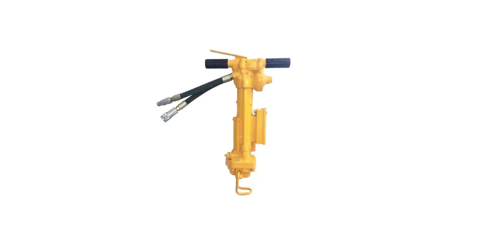
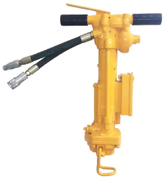
STANLEY SKV20130A V Series Sinker Drill
IMPORTANT
To fill out a Product Warranty Validation form, and for information on your warranty, visit Stanleyhydraulics.com and select the Company tab, Warranty. (NOTE: The warranty Validation record must be submitted to validate the warranty).
SERVICING:
This manual contains safety, operation, and routine maintenance instructions. Stanley Hydraulic Tools recommends that servicing of hydraulic tools, other than routine maintenance, must be performed by an authorized and certified dealer. Please read the following warning.
WARNING
- SERIOUS INJURY OR DEATH COULD RESULT FROM THE IMPROPER REPAIR OR SERVICE OF THIS TOOL.
- REPAIRS AND / OR SERVICE TO THIS TOOL MUST ONLY BE DONE BY AN AUTHORIZED AND CERTIFIED DEALER.
For the nearest authorized and certified dealer, call Stanley Hydraulic Tools at (503-659-5660) and ask for a Customer Service Representative.
SAFETY SYMBOLS
Safety symbols and signal words, as shown below, are used to emphasize all operator, maintenance, and repair actions that, if not strictly followed, could result in a life-threatening situation, bodily injury or damage to equipment.
- This is the safety alert symbol. It is used to alert you to potential personal injury hazards. Obey all safety messages that follow this symbol to avoid possible injury or death.
- DANGER
This safety alert and signal word indicate an imminently hazardous situation which, if not avoided, will result in death or serious injury. - WARNING
This safety alert and signal word indicate a potentially hazardous situation which, if not avoided, could result in death or serious injury. - CAUTION
This safety alert and signal word indicate a potentially hazardous situation which, if not avoided, could result in death or serious injury. - CAUTION
This signal word indicates a potentially hazardous situation which, if not avoid- ed, may result in property damage. - NOTICE
This signal word indicates a situation which, if not avoided, will result in damage to the equipment. - IMPORTANT
This signal word indicates a situation which, if not avoided, may result in dam- age to the equipment.
Always observe safety symbols. They are included for your safety and for the protection of the tool.
LOCAL SAFETY REGULATIONS
Enter any local safety regulations here. Keep these instructions in an area accessible to the operator and mainte- nance personnel.
SAFETY PRECAUTIONS
Tool operators and maintenance personnel must always comply with the safety precautions given in this manual and on the stickers and tags attached to the tool and hose.
These safety precautions are given for your safety. Re-view them carefully before operating the tool and before performing general maintenance or repairs. Supervising personnel should develop additional precautions relating to the specific work area and local safety regulations. If so, place the added precautions in the space provided in this manual. The model SKV20130A will provide safe and dependable service if operated in accordance with the instructions given in this manual. Read and understand this manual and any stickers and tags attached to the tool and hoses before operation. Failure to do so could result in personal injury or equipment damage.
- Operator must start in a work area without bystand- ers. The operator must be familiar with all prohibited work areas such as excessive slopes and danger- ous terrain conditions.
- Establish a training program for all operators to en- sure safe operations.
- Do not operate the tool unless thoroughly trained or under the supervision of an instructor.
- Always wear safety equipment such as goggles, head protection, and safety shoes at all times when operating the tool.
- Do not inspect or clean the tool while the hydraulic power source is connected. Accidental engagement of the tool can cause serious injury.
- Do not operate this tool without first reading the Operation section.
- Do not install or remove this tool while the hydraulic power source is connected. Accidental engagement of the tool can cause serious injury.
- Never operate the tool near energized transmission lines. Know the location of buried or covered services before starting work.
- Do not wear loose-fitting clothing when operating the tool. Loose-fitting clothing can get entangled with the tool and cause serious injury.
- Supply hoses must have a minimum working pressure rating of 2500 psi/175 bar.
- Be sure all hose connections are tight.
- The hydraulic circuit control valve must be in the “OFF” position when coupling or uncoupling the tool. Wipe all couplers clean before connecting. Failure to do so may result in damage to the quick couplers and cause overheating. Use only lint-free clothes.
- Do not operate the tool at oil temperatures above 140 °F/60 °C. Operation at higher oil temperatures can cause operator discomfort and may cause damage to the tool.
- Do not operate a damaged, improperly adjusted, or incompletely assembled tool.
- To avoid personal injury or equipment damage, all tool repair, maintenance and service must only be performed by authorized and properly trained personnel.
- Do not exceed the rated limits of the tool or use the tool for applications beyond its design capacity.
- Always keep critical tool markings, such as labels and warning stickers legible.
- Always replace parts with replacement parts recommended by Stanley.
- Check fastener tightness often and before each use daily.
- Do not put your hands or any other body part under the volute while the trash pump is running.
- Do not lift the trash pump by pulling on the hydraulic hoses. Use a suitable line fastened to the trash pump handle.
- Do not point water discharge toward bystanders.
HOSE TYPES
The rated working pressure of the hydraulic hose must be equal to or higher than the relief valve setting on the hydraulic system. There are three types of hydraulic hose that meet this requirement and are authorized for use with Stanley Hydraulic Tools. They are:
- Certified non-conductive — constructed of thermoplastic or synthetic rubber inner tube, synthetic fiber braid reinforcement, and weather-resistant thermoplastic or synthetic rubber cover. Hose labeled certified non-conductive is the only hose authorized for use near electrical conductors.
- Wire-braided (conductive) — constructed of synthetic rubber inner tube, single or double wire braid reinforcement, and weather-resistant synthetic rubber cover. This hose is conductive and must never be used near electrical conductors.
- Fabric-braided (not certified or labeled non-conductive) — constructed of thermoplastic or synthetic rubber in-ner tube, synthetic fiber braid reinforcement, and weather-resistant thermoplastic or synthetic rubber cover. This hose is not certified non-conductive and must never be used near electrical conductors.
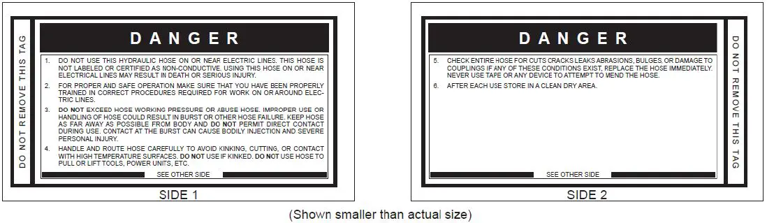
HOSE SAFETY TAGS
To help ensure your safety, the following DANGER tags are attached to all hose purchased from Stanley Hydraulic Tools. DO NOT REMOVE THESE TAGS. If the information on a tag is illegible because of wear or damage, replace the tag immediately. A new tag may be obtained from your Stanley Distributor.
THE TAG SHOWN BELOW IS ATTACHED TO THE “CERTIFIED NON-CONDUCTIVE” HOSE
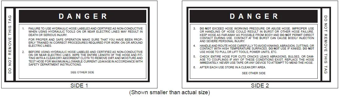
THE TAG SHOWN BELOW IS ATTACHED TO THE “CONDUCTIVE” HOSE.
Tool to Hydraulic Circuit Hose Recommendations
The chart to the right shows recommended minimum hose diameters for various hose lengths based on gallons per minute (gpm)/ liters per minute (lpm). These recommendations are intended to keep return line pressure (back pressure) to a minimum acceptable lev- el to ensure maximum tool performance.
This chart is intended to be used for hydraulic tool applications only based on Stanley Hydraulic tools tool operating requirements and should not be used for any other applications.
- All hydraulic hoses must have at least a rated minimum working pressure equal to the maximum hydraulic system relief valve setting.
- All hydraulic hoses must meet or exceed specifications as set forth by SAE J517.
| Oil Flow | Hose Lengths | Inside Diameter | USE (Press/Return) | Min. Working Pressure | ||||
| GPM | LPM | FEET | METERS | INCH | MM | PSI | BAR | |
| Certified Non-Conductive Hose – Fiber Braid – for Utility Bucket Trucks | ||||||||
| 4-9 | 15-34 | up to 10 | up to 3 | 3/8 | 10 | Both | 2250 | 155 |
| Conductive Hose – Wire Braid or Fiber Braid -DO NOT USE NEAR ELECTRICAL CONDUCTORS | ||||||||
| 4-6 | 15-23 | up to 25 | up to 7.5 | 3/8 | 10 | Both | 2500 | 175 |
| 4-6 | 15-23 | 26-100 | 7.5-30 | 1/2 | 13 | Both | 2500 | 175 |
| 5-10.5 | 19-40 | up to 50 | up to 15 | 1/2 | 13 | Both | 2500 | 175 |
| 5-10.5 | 19-40 | 51-100 | 15-30 | 5/8 | 16 | Both | 2500 | 175 |
| 5-10.5 | 19-40 | 100-300 | 30-90 | 5/8 | 16 | Pressure | 2500 | 175 |
| 3/4 | 19 | Return | 2500 | 175 | ||||
| 10-13 | 38-49 | up to 50 | up to 15 | 5/8 | 16 | Both | 2500 | 175 |
| 10-13 | 38-49 | 51-100 | 15-30 | 5/8 | 16 | Pressure | 2500 | 175 |
| 3/4 | 19 | Return | 2500 | 175 | ||||
| 10-13 | 38-49 | 100-200 | 30-60 | 3/4 | 19 | Pressure | 2500 | 175 |
| 1 | 25.4 | Return | 2500 | 175 | ||||
| 13-16 | 49-60 | up to 25 | up to 8 | 5/8 | 16 | Pressure | 2500 | 175 |
| 3/4 | 19 | Return | 2500 | 175 | ||||
| 13-16 | 49-60 | 26-100 | 8-30 | 3/4 | 19 | Pressure | 2500 | 175 |
| 1 | 25.4 | Return | 2500 | 175 | ||||
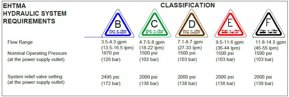
HTMA/EHTMA REQUIREMENTS3
HTMA TOOL TYPE
| HYDRAULIC SYSTEM REQUIREMENTS TYPE I TYPE II TYPE RR TYPE III Flow Range 4-6 gpm 7-9 gpm 9-10.5 gpm 11-13 gpm (15-23 lpm) (26-34 lpm) (34-40 lpm) (42-49 lpm) Nominal Operating Pressure 1500 psi 1500 psi 1500 psi 1500 psi (at the power supply outlet) (103 bar) (103 bar) (103 bar) (103 bar) |
| System relief valve setting 2100-2250 psi 2100-2250 psi 2200-2300 psi 2100-2250 psi (at the power supply outlet) (145-155 bar) (145-155 bar) (152-159 bar) (145-155 bar) |
| Maximum back pressure 250 psi 250 psi 250 psi 250 psi (at tool end of the return hose) (17 bar) (17 bar) (17 bar) (17 bar)
Measured at a max. fluid viscosity of: 400 ssu* 400 ssu* 400 ssu* 400 ssu* (at min. operating temperature) (82 centistokes) (82 centistokes) (82 centistokes) (82 centistokes) |
| Temperature: Sufficient heat rejection 140° F 140° F 140° F 140° F capacity to limit max. fluid temperature to: (60° C) (60° C) (60° C) (60° C) (at max. expected ambient temperature)
Min. cooling capacity at a temperature 3 hp 5 hp 6 hp 7 hp difference of between ambient and fluid (2.24 kW) (3.73 kW) (5.22 kW) (4.47 kW) temps 40° F 40° F 40° F 40° F NOTE: (22° C) (22° C) (22° C) (22° C) Do not operate the tool at oil temperatures above 140° F (60° C). Operation at higher temperatures can cause operator discomfort at the tool. |
| Filter 25 microns 25 microns 25 microns 25 microns Min. full-flow filtration 30 gpm 30 gpm 30 gpm 30 gpm Sized for flow of at least: (114 lpm) (114 lpm) (114 lpm) (114 lpm) (For cold temp. startup and max. dirt-holding capacity)
Hydraulic fluid Petroleum based 100-400 ssu* 100-400 ssu* 100-400 ssu* 100-400 ssu* (premium grade, anti-wear, non-conductive) (20-82 centistokes) Viscosity (at min. and max. operating temps) NOTE: When choosing hydraulic fluid, the expected oil temperature extremes that will be experienced in service determine the most suitable temperature viscosity characteristics. Hydraulic fluids with a viscosity index over 140 will meet the requirements over a wide range of operating temperatures. *SSU = Saybolt Seconds Universal |
OPERATION
PREOPERATION PROCEDURES CHECK THE POWER SOURCE
- Each sinker drill has been assembled before leaving the factory, so it is necessary to check whether there is any damage caused in the shipping process or whether there is debris
- entrained in the assembly when the first use
- Using a calibrated flow meter and pressure gauge, make sure the hydraulic power source develops a flow of 20 Ipm at 155 bar.
- Make certain that the power source is equipped with a relief valve set to open at 2100-2250 psi/145-155 bar maximum.
- Make certain that the power source returns pressure
CHECK TOOLS
- Make sure all tool parts are properly assembled
- Make sure There was no oil leak
- Make sure all assemblies must be clean and all accessories and interfaces must be securely assembled
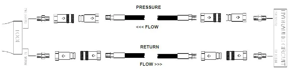
CONNECT HOSES
- Wipe all hose couplers with a clean lint-free cloth before making connections.
- Connect the hoses from the hydraulic power source to the couplers on the sinker drill.
- Observe the arrow on the couplers to ensure the flow is in the proper direction.
NOTE:
If uncoupled hoses are left in the sun, pressure in- crease inside the hoses might make them difficult to connect. Whenever possible, connect the free ends of the hoses together.
OPERATION
- Observe all safety precautions.
- Connect the hydraulic hose, and clean the coupler before the connection.
- Focus on the object you plan to work on.
IMPORTANT
Never point the hose at bystanders. - Put the hydraulic control valve in the “ON”.
- Turn on the hydraulic power source to start the operation.
- When operating, first turn the knob switch to 0 positions, and then punch a small pit on the working surface to facilitate the positioning of the drill bit.
- Adjust the know switch to the appropriate level (1-3) for working.
COLD WEATHER OPERATION
If the tool is to be used during cold weather, preheat the hy dr aul ic fluid at low engine speed. When using the normally recommended fluids, fluid temperature should be at or above 50 °F/10 °C (400 ssu/82 centistokes) before use.
Drill deep holes for operation
- When the depth of the drilling hole is more than 1 meter, an external air source is required for operation. An external air source pipe is inserted at the lower inlet hole.
TROUBLESHOOTING
If symptoms of poor performance develop, the following chart can be used as a guide to correct the problem. When diagnosing faults in the operation of the tool, always make sure the hydraulic power source is supplying the correct hydraulic flow and pressure as listed in the table. Use a flowmeter know to be accurate. check the flow with the hydraulic fluid temperature of at least 80 °F/27 °C.
| PROBLEM | CAUSE | SOLUTI ON |
| Sinker drill will not work | No hydraulic fluid flow or pressure. | Turn on power unit and check that 7–11 gpm/26-40 lpm at 2000 psi/140 bar is available |
| Impeller jammed with debris. | Clean the pumping chamber. | |
| Defective inlet/ return hose | Check and adjust the hose. | |
| Poor performance. | Improper hydraulic fluid flow. | Check that 7–11 gpm/26–40 lpm at 2000 psi/140 bar is available |
| Sinker drill inlet hose or coupler restricted. | Remove restriction and thoroughly clean. | |
| Discharge hose kinked or restricted. | Straighten the hoes. If the hose must bend at the top of the hole, use a piece of split rigid conduit with large diameter of the expanded hose. This keeps the hose from kinking. Use a 90° 4-inch pipe elbow on the trash pump outlet if necessary. | |
| The temperature of the hydraulic oil is too high(>60°C) | ||
| Use a cooling device to cool | ||
SPECIFICATIONS
- Weight ………………………………………………………………………………………………………………………………….. 20 kg
- Flow Range …………………………………………………………………………………………………………………………… 20-25lpm
- Working pressure …………………………………………………………………………………………………………………… 90-140bar
- Nitrogen pressure ………………………………………………………………………………………………………………….. 40bar
- Size ……………………………………………………………………………………………………………………………………… 550x350x130mm
- Rotate speed ………………………………………………………………………………………………………………………… 0-400rpm
- Drill bit diameter …………………………………………………………………………………………………………………….. 38-50mm
- Max drill depth ………………………………………………………………………………………………………………………. 3m
- Percussive Power ………………………………………………………………………………………………………………….. 50J
- Torque …………………………………………………………………………………………………………………………………. 15Nm
- Air compressor pressure ……………………………………………………………………………………………………0.08m3/min , 2bar
PARTS ILLUSTRATION
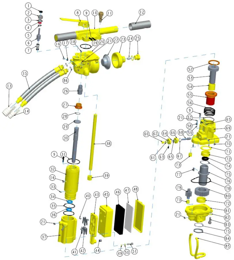
PARTS LIST
| No. | Item | Qty | Description |
| 1 | MFJ0001 | 1 | ROD WIPER |
| 2 | LBK16003 | 1 | OIL SEAT |
| 3 | MFJ0145 | 1 | O-RING |
| 4 | MFJ0002 | 1 | CUP SEAL |
| 5 | BZJ0001 | 1 | CIRCLIP |
| 6 | LDHD2042 | 1 | SWITCH VALVE |
| 7 | BZJ0035 | 1 | COMPRESSION SPRING |
| 8 | LBK18004 | 1 | TRIGGER |
| 9 | BZJ0420 | 4 | ROLL PIN |
| 10 | LDHD2041 | 1 | HANDLE |
| 11 | LDHD2040 | 4 | HANDLE FIXING BOLT |
| 12 | LBK18005 | 2 | HANDLE GRIP |
| 13 | LBK18033 | 1 | 3/8 FEMAIE COUPLER |
| 14 | LBK18034 | 1 | 3/8 MALE COUPLER |
| 15 | LBK18032 | 2 | HOSE ASSY |
| 16 | BZJ1202 | 14 | SET SCREW |
| 17 | LBK16021 | 1 | ORIFICE PLUG |
| 18 | BZJ0518 | 1 | HIGH PRESSURE PLUG |
| 19 | MFJ0013 | 1 | O-RING |
| 20 | LBK16010 | 1 | BREAK FOOT |
| 21 | BZJ0522 | 9 | SET SCREW |
| 22 | LBK16018 | 1 | ACCUMULATOR DIAPHRAGM |
| 23 | LBK16014 | 1 | ACCUMULATOR HOUSING |
| 24 | LBK1820499 | 1 | NITROGEN CHARGE |
| 25 | LBK18002 | 1 | PLUG |
| 26 | LDHD2014 | 1 | RESERSING VALVE |
| 27 | LDHD2015 | 1 | RESERSING VALVE BASE |
| 28 | MFJ0251 | 1 | O-RING |
| 29 | LDHD2012 | 1 | VALVE BASE |
| 30 | LDHD2001 | 1 | PISTON |
| 31 | MFJ0141 | 1 | O-RING |
| 32 | LDHD2013 | 1 | SLEEVE |
| 33 | BZJ0419 | 1 | ROLL PIN |
| 34 | MFJ0016 | 1 | U SEAL |
| 35 | MFJ0013 | 2 | O-RING |
| 36 | MFJ0017 | 1 | DUST SEAL |
| 37 | LDHD2010 | 1 | AIR COMPRESSOR HOUSING |
| 38 | LDHD2025 | 2 | ROD |
| 39 | LBK16013 | 2 | ROD SCREW |
| 40 | BZJ0534 | 8 | HEAD SCREW |
| 41 | LDHD2020 | 4 | FILTER |
| 42 | LDHD2021 | 4 | FILTER |
| 43 | LDHD2017 | 1 | AIR INLET BASE |
| 44 | BZJ1296 | 1 | END CAP |
| 45 | LDHD2019 | 1 | INLET BOX |
| 46 | LDHD2034 | 1 | SPONGE |
| 47 | LDHD2033 | 1 | FILTER SPONGE |
| 48 | LDHD2018 | 1 | INLET BOX CAP |
| 49 | BZJ0164 | 4 | WASHER |
| 50 | BZJ0342 | 4 | WASHER |
| 51 | BZJ0364 | 4 | M6*20 HEX SOCKET SCREW |
| 52 | LDHD2031 | 1 | SEAL |
| 53 | LDHD2022 | 1 | PISTON |
| 54 | LDHD2027 | 1 | BEARING SLEEVE |
| 55 | LDHD2016 | 1 | PISTON BUSH |
| 56 | BZJ1204 | 1 | SPRING |
| 57 | MFJ0014 | 1 | O-RING |
| 58 | BZJ1203 | 1 | SPRING |
| 59 | BZJ0091 | 1 | STEEL BALL |
| 60 | LDHD2011 | 1 | ROTATE VALVE CAP |
| 61 | MFJ0120 | 1 | WASHER |
| 62 | LDHD2008 | 1 | KNOB |
| 63 | BZJ0506 | 1 | SCREW |
| 64 | MFJ0019 | 1 | RING |
| 65 | MFJ0012 | 3 | O-RING |
| 66 | LDHD2009 | 1 | ROTATE VALVE BASE |
| 67 | MFJ0043 | 1 | O-RING |
| 68 | LDHD2007 | 1 | ROTATE VALVE |
| 69 | LDHD2023 | 1 | MOTOR |
| 70 | BZJ0533 | 2 | PIN |
| 71 | LDHD2006 | 1 | COPPER WASHER |
| 72 | LDHD2028 | 2 | BUSHING |
| 73 | LDHD2026 | 2 | BEARING BUSH |
| 74 | LDHD2038 | 1 | DUST SEAL |
| 75 | MFJ0249 | 2 | SEAL |
| 76 | LDHD2005 | 1 | SLEEVE |
| 77 | BZJ0149 | 1 | KEY |
| 78 | MFJ0015 | 1 | O-RING |
| 79 | LDHD2002 | 1 | DRIVING GEAR |
| 80 | LDHD2003 | 1 | DRIVEN GEAR |
| 81 | LDHD2004 | 1 | GEAR HOUSING |
| 82 | BZJ0162 | 4 | WASHER |
| 83 | BZJ0363 | 4 | SCREW |
| 84 | MFJ0421 | 1 | DUST SEAL |
| 85 | LDHD2024 | 1 | LATCH |
| 86 | MFJ0251 | 1 | O-RING |
Hefei INTACA Science-Technology Development Co., Ltd.
Add A-7 Building Gongtou-Liheng Industry Square, Western Section Fanhua Street(the Cross Wenshan Road), Hefei, Anhui, China
Tel: 0551-63498781/2/3
Fax: 0551-63498780 P.C.:230601
Web: http://www.stanleyinfrastructure.com.cn/.


