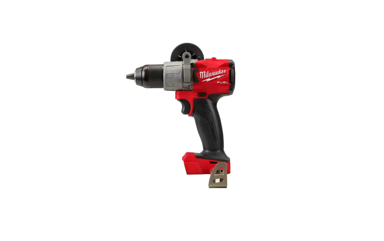
milwaukee J77A Hammer Drill

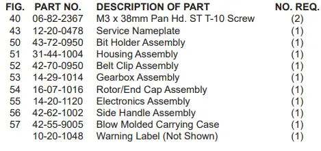
SERVICE PARTS LIST
| SPECIFY CATALOG NO. AND SERIAL NO. WHEN ORDERING PARTS | REVISED BULLETIN | DATE Oct. 2020 | ||
| M18™ FUEL™ Brushless Hammer-Drill | ||||
| WIRING INSTRUCTION SEE PAGE 2 | ||||
| CATALOG NO. 2804-20 | STARTING J77A SERIAL NO. | |||
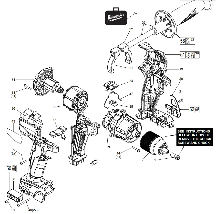
| FIG. 1 | PART NO. 05-88-0019 | DESCRIPTION OF PART M8.0 x 1 LH T-40 Chuck Screw | NO. REQ. (1) | |||
| 2 | 42-66-1006 | 1/2” Keyless Chuck | (1) | |||
| 13 | 06-82-7336 | M4 x 20mm Pan Hd. ST T-10 Screw | (4) | |||
| 14 | 06-82-7337 | M4 x 20mm Washer Pan Hd. ST T-10 Scr. | (4) | |||
| 16 | 42-42-3001 | Forward/Reverse Shuttle | (1) | |||
| 17 | 45-24-1045 | Speed Change Lever | (1) | |||
| 19 | ————— | Left Housing Halve – Support | (1) | |||
| 20 | ————— | Belt Clip | (1) | |||
| 21 | 06-82-2500 | 6-32 x 7mm Pan Hd. Taptite T-15 Screw | (2) | |||
| 31 | ————— | Secondary Clamp Body | (1) | |||
| 32 | ————— | Primary Clamp Body | (1) | |||
| 33 | ————— | Threaded Side Handle | (1) | |||
| 34 | 44-10-4002 | Speed Selector Slide | (1) | |||
| 35 | 40-50-9001 | Detent Spring | (1) | |||
| 36 | ————— | Right Housing Halve – Cover | (1) | |||
| 38 | ————— | Bit Holder with Clip | (1) | |||
| 39 | 06-82-6350 | M3 x 16mm Pan Hd. ST T-10 Screw | (5) | |||
REMOVING THE CHUCK SCREW
Set the Speed Selector Slide (34) to the #1 setting. With the aid of a small pencil tip torch (or use an air reduction nozzle on a heat gun) apply heat into the chuck opening, directly to the head of reversing screw just prior to removing the screw. Place a T40 1/4” torx bit into the head of the reversing screw and place a 1/4” boxed end wrench over the hex on the T40 bit. It is recommended to use a 12”-18” metal tube or pipe as leverage over the boxed wrench. In a clockwise direction apply a slow, steady force on the ‘cheater bar’ to break the screw loose.
REMOVING THE KEYLESS CHUCK:
Tighten a 3/8” or 10mm Allen Key into the jaws of the chuck. Place the tool into a vise with soft jaws (this will require that you remove the belt clip from the tool). It is recommended to use a 12”-18” metal tube or pipe as leverage over the allen key. In a counter-clockwise direction apply a slow, steady force on the ‘cheater bar’ to break the chuck loose.
INSTALLING NEW CHUCK AND SCREW:
Torque Chuck to 1095 kg/cm (950.418 in/lbs or 28.93 ft/lbs) Torque Screw to 461 kg/cm (400.130 in/lbs or 33.34 ft/lbs).
WIRING
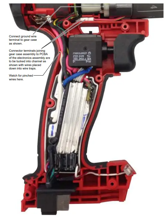
- Be sure that all mechanical and electrical components are placed firmly and squarely in the corresponding cavities of the left housing halve.
- Be very careful and make sure that all wires and the wire ribbon are placed firmly down in wire channels and traps.
- Make sure there are no interferences when installing the right housing half.
ATTENTION
OBSERVE PRECAUTIONS FOR HANDLING ELECTROSTATIC-SENSITIVE DEVICES
MILWAUKEE TOOL
www.milwaukeetool.com
13135 W. Lisbon Rd., Brookfield, WI 53005


