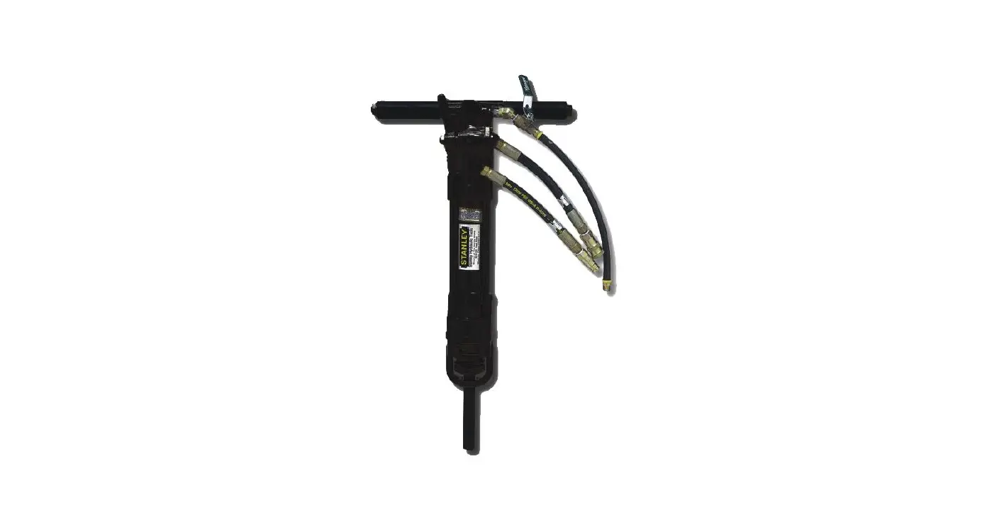
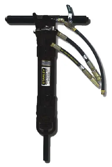
STANLEY SK58 Hydraulic Sinker Drill
SAFETY PRECAUTIONS
Tool operators and maintenance personnel must comply with the safety precautions given in this manual and on the stickers and tags attached to the tool and hose.
These precautions are given for your safety. Review them carefully before operating the tool and before performing general maintenance or repairs.
Supervising personnel should develop additional precautions relating to the specific work area and local safety regulations. Place the added precautions in the space provided in this manual.
The SK58 Hydraulic Sinker Drill will provide safe and dependable service if operated in accordance with the instructions given in this manual. Read and understand this manual and any stickers and tags attached to the tool and hoses before operation. Failure to do so could result in personal injury or equipment damage.
- Operator must start in a work area without bystanders. The operator must be familiar with all prohibited work areas such as excessive slopes and dangerous terrain conditions.
- Establish a training program for all operators to ensure safe operation.
- Do not operate the tool unless thoroughly trained or under the supervision of an instructor.
- Always wear safety equipment such as goggles, ear, head protection and safety shoes at all times when operating the tool.
- Do not inspect or clean the tool while the hydraulic power source is connected. Accidental engagement of the tool can cause serious injury.
- Supply hoses must have a minimum working pressure rating of 2500 psi/175 bar.
- Be sure all hose connections are tight.
- The hydraulic circuit control valve must be in the “OFF” position when coupling or uncoupling the tool. Wipe all couplers clean before connecting. Use only lint-free cloths. Failure to do so may result in damage to the quick couplers and cause overheating of the hydraulic system.
- Do not operate the tool at oil temperatures above 140°F/60°C. Operation at higher oil temperatures can cause operator discomfort and may damage the tool.
- Do not operate a damaged, improperly adjusted or incompletely assembled tool.
- Do not weld, cut with an acetylene torch or hard-face the tool bit.
- To avoid personal injury or equipment damage, all tool repair, maintenance and service must only be performed by authorized and properly trained personnel.
- Do not exceed the rated limits of the tool or use the tool for applications beyond its design capacity.
- Always keep critical tool markings, such as labels and warning stickers, legible.
- Always replace parts with replacement parts recommended by STANLEY.
- Check fastener tightness often and before each use daily.
- Do not operate the tool if underground utilities are present.
- Do not wear loose fitting clothing when operating the tool.
- WARNING: Some dust created by power sanding, sawing, grinding, drilling, and other construction activities contains chemicals known to the State of California to cause cancer, birth defects or other reproductive harm. Some examples of these chemicals are:
- Lead from lead-based paints,
- crystalline silica from bricks and cement and other masonry products, and
- arsenic and chromium from chemically treated lumber.
Your risk from these exposures varies, depending on how often you do this type of work. To reduce your exposure to these chemicals: work in a well ventilated area, and work with approved safety equipment, such as those dust masks that are specially designed to filter out microscopic particles.
Protect yourself and those around you. Research and understand the materials you are cutting. Follow correct safety procedures and comply with all applicable national, state or provisional health and safety regulations relating to them, including, if appropriate arranging for the safe disposal of the materials by a qualified person.
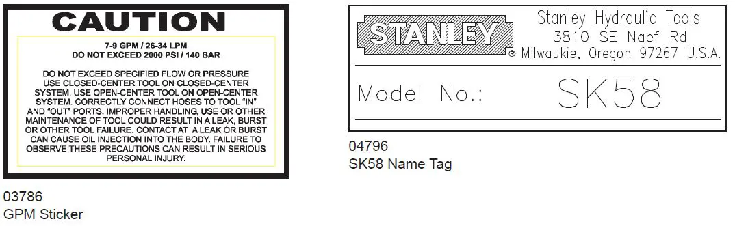
TOOL STICKERS & TAGS
NOTE:
THE INFORMATION LISTED ON THE STICKERS SHOWN, MUST BE LEGIBLE AT ALL TIMES.
REPLACE DECALS IF THEY BECOME WORN OR DAMAGED. REPLACEMENTS ARE AVAILABLE FROM YOUR LOCAL STANLEY DISTRIBUTOR.
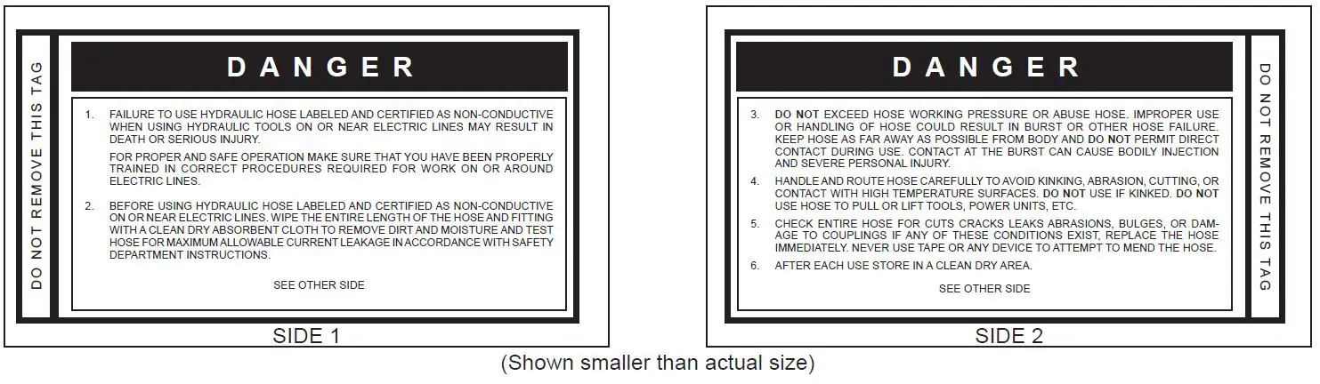
The safety tag (P/N 15875) at right is attached to the tool when shipped from the factory. Read and understand the safety instructions listed on this tag before removal. We suggest you retain this tag and attach it to the tool when not in use.
D A N G E R
- FAILURE TO USE HYDRAULIC HOSE LABELED AND CERTIFIED AS NON-CONDUCTIVE WHEN USING HYDRAULIC TOOLS ON OR NEAR ELECTRICAL LINES MAY RESULT IN DEATH OR SERIOUS INJURY. BEFORE USING HOSE LABELED AND CERTIFIED AS NONCONDUCTIVE ON OR NEAR ELECTRIC LINES BE SURE THE HOSE IS MAINTAINED AS NON-CONDUCTIVE. THE HOSE SHOULD BE REGULARLY TESTED FOR ELECTRIC CURRENT LEAKAGE IN ACCORDANCE WITH YOUR SAFETY DEPARTMENT INSTRUCTIONS.
- A HYDRAULIC LEAK OR BURST MAY CAUSE OIL INJECTION INTO THE BODY OR CAUSE OTHER SEVERE PERSONAL INJURY.
A. DO NOT EXCEED SPECIFIED FLOW AND PRESSURE FOR THIS TOOL. EXCESS FLOW OR PRESSURE MAY CAUSE A LEAK OR BURST.
B. DO NOT EXCEED RATED WORKING PRESSURE OF HYDRAULIC HOSE USED WITH THIS TOOL. EXCESS PRESSURE MAY CAUSE A LEAK OR BURST.
C. CHECK TOOL HOSE COUPLERS AND CONNECTORS DAILY FOR LEAKS. DO NOT FEEL FOR LEAKS WITH YOUR HANDS. CONTACT WITH A LEAK MAY RESULT IN SEVERE PERSONAL INJURY.
D. DO NOT LIFT OR CARRY TOOL BY THE HOSES. DO NOT ABUSE HOSE. DO NOT USE KINKED, TORN OR DAMAGED HOSE. - MAKE SURE HYDRAULIC HOSES ARE PROPERLY CONNECTED TO THE TOOL BEFORE PRESSURING SYSTEM. SYSTEM PRESSURE HOSE MUST ALWAYS BE CONNECTED TO TOOL “IN” PORT. SYSTEM RETURN HOSE MUST ALWAYS BE CONNECTED TO TOOL “OUT” PORT. REVERSING CONNECTIONS MAY CAUSE REVERSE TOOL OPERATION WHICH CAN RESULT IN SEVERE PERSONAL INJURY.
- DO NOT CONNECT OPEN-CENTER TOOLS TO CLOSEDCENTER HYDRAULIC SYSTEMS. THIS MAY RESULT IN LOSS OF OTHER HYDRAULIC FUNCTIONS POWERED BY THE SAME SYSTEM AND/OR SEVERE PERSONAL INJURY.
- BYSTANDERS MAY BE INJURED IN YOUR WORK AREA. KEEP BYSTANDERS CLEAR OF YOUR WORK AREA.
- WEAR HEARING, EYE, FOOT, HAND AND HEAD PROTECTION.
- TO AVOID PERSONAL INJURY OR EQUIPMENT DAMAGE, ALL TOOL REPAIR MAINTENANCE AND SERVICE MUST ONLY BE PERFORMED BY AUTHORIZED AND PROPERLY TRAINED PERSONNEL.
IMPORTANT
READ OPERATION MANUAL AND SAFETY INSTRUCTIONS FOR THIS TOOL BEFORE USING IT. USE ONLY PARTS AND REPAIR PROCEDURES APPROVED BY STANLEY AND DESCRIBED IN THE OPERATION MANUAL.
TAG TO BE REMOVED ONLY BY TOOL OPERATOR. SEE OTHER SIDE
SAFETY TAG P/N 15875 (Shown smaller then actual size)
HOSE TYPES
The rated working pressure of the hydraulic hose must be equal to or higher than the relief valve setting on the hydraulic system. There are three types of hydraulic hose that meet this requirement and are authorized for use with STANLEY hydraulic tools. They are:
Certified non-conductive – constructed of thermoplastic or synthetic rubber inner tube, synthetic fiber braid reinforcement, and weather resistant thermoplastic or synthetic rubber cover. Hose labeled certified non-conductive is the only hose authorized for use near electrical conductors.
Wire-braided (conductive) – constructed of synthetic rubber inner tube, single or double wire braid reinforcement, and weather resistant synthetic rubber cover. This hose is conductive and must never be used near electrical conductors.
Fabric-braided (not certified or labeled non-conductive) – constructed of thermoplastic or synthetic rubber inner tube, synthetic fiber braid reinforcement, and weather resistant thermoplastic or synthetic rubber cover. This hose is not certified non-conductive and must never be used near electrical conductors.
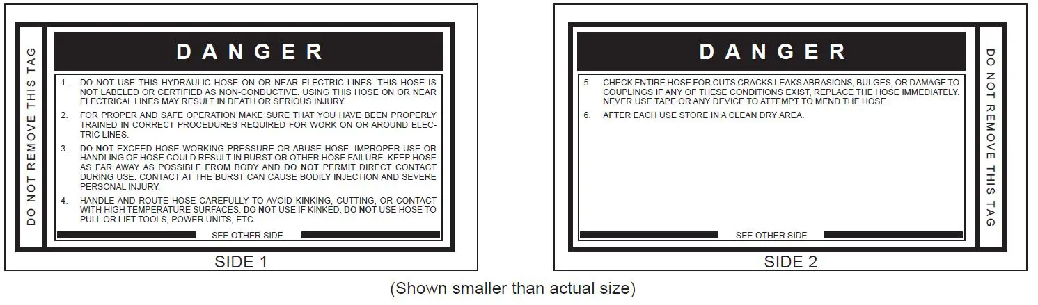
To help ensure your safety, the following DANGER tags are attached to all hose purchased from STANLEY. DO NOT REMOVE THESE TAGS.
If the information on a tag is illegible because of wear or damage, replace the tag immediately. A new tag may be obtained from your STANLEY Distributor.
THE TAG SHOWN BELOW IS ATTACHED TO “CERTIFIED NON-CONDUCTIVE” HOSE
THE TAG SHOWN BELOW IS ATTACHED TO “CONDUCTIVE” HOSE.
HOSE RECOMMENDATIONS
Tool to Hydraulic Circuit Hose Recommendations
The chart to the right shows recommended minimum hose diameters for various hose lengths based on gallons per minute (GPM)/liters per minute (LPM). These recommendations are intended to keep return line pressure (back pressure) to a minimum acceptable level to ensure maximum tool performance.
This chart is intended to be used for hydraulic tool applications only based on STANLEY tool operating requirements and should not be used for any other applications.
All hydraulic hose must have at least a rated minimum working pressure equal to the maximum hydraulic system relief valve setting.
All hydraulic hose must meet or exceed specifications as set forth by SAE J517.
| Oil Flow | Hose Lengths | Inside Diameter | USE (Press/Return) | Min. Working Pressure | ||||
| GPM | LPM | FEET | METERS | INCH | MM | PSI | BAR | |
| Certified Non-Conductive Hose – Fiber Braid – for Utility Bucket Trucks | ||||||||
| 4-9 | 15-34 | up to 10 | up to 3 | 3/8 | 10 | Both | 2250 | 155 |
| Conductive Hose – Wire Braid or Fiber Braid -DO NOT USE NEAR ELECTRICAL CONDUCTORS | ||||||||
| 4-6 | 15-23 | up to 25 | up to 7.5 | 3/8 | 10 | Both | 2500 | 175 |
| 4-6 | 15-23 | 26-100 | 7.5-30 | 1/2 | 13 | Both | 2500 | 175 |
| 5-10.5 | 19-40 | up to 50 | up to 15 | 1/2 | 13 | Both | 2500 | 175 |
| 5-10.5 | 19-40 | 51-100 | 15-30 | 5/8 | 16 | Both | 2500 | 175 |
| c 5-10.5 | 19-40 | 100-300 | 30-90 | 5/8 | 16 | Pressure | 2500 | 175 |
| 3/4 | 19 | Return | 2500 | 175 | ||||
| 10-13 | 38-49 | up to 50 | up to 15 | 5/8 | 16 | Both | 2500 | 175 |
| 10-13 | 38-49 | 51-100 | 15-30 | 5/8 | 16 | Pressure | 2500 | 175 |
| 3/4 | 19 | Return | 2500 | 175 | ||||
| 10-13 | 38-49 | 100-200 | 30-60 | 3/4 | 19 | Pressure | 2500 | 175 |
| 1 | 25.4 | Return | 2500 | 175 | ||||
| 13-16 | 49-60 | up to 25 | up to 8 | 5/8 | 16 | Pressure | 2500 | 175 |
| 3/4 | 19 | Return | 2500 | 175 | ||||
| 13-16 | 49-60 | 26-100 | 8-30 | 3/4 | 19 | Pressure | 2500 | 175 |
| 1 | 25.4 | Return | 2500 | 175 | ||||
HTMA / EHTMA REQUIREMENTS
| HTMA HYDRAULIC SYSTEM REQUIREMENTS | TOOL TYPE | |||
| TYPE I | TYPE II | TYPE RR | TYPE III | |
| Flow range | 4-6 GPM (15-23 LPM) | 7-9 GPM (26-34 LPM) | 9-10.5 GPM (34-40 LPM) | 11-13 GPM (42-49 LPM) |
| Nominal operating pressure (At the power supply outlet) | 1500 psi (103 bar) | 1500 psi (103 bar) | 1500 psi (103 bar) | 1500 psi (103 bar) |
| System relief valve setting (At the power supply outlet) | 2100-2250 psi (145-155 bar) | 2100-2250 psi (145-155 bar) | 2200-2300 psi (152-159 bar) | 2100-2250 psi (145-155 bar) |
| Maximum back pressure (At tool end of the return hose) | 250 psi (17 bar) | 250 psi (17 bar) | 250 psi (17 bar) | 250 psi (17 bar) |
| Measured at a max fluid viscosity of: (At minimum operating temperature) | 400 ssu* (82 centistokes) | 400 ssu* (82 centistokes) | 400 ssu* (82 centistokes) | 400 ssu* (82 centistokes) |
| Temperature: Sufficient heat rejection capacity to limit maximum fluid temperature to: (At maximum expected ambient temperature) | 140°F (60°C) | 140°F (60°C) | 140°F (60°C) | 140°F (60°C) |
| Minimum cooling capacity at a temperature difference of between ambient and fluid temps | 3 hp (2.24 kW) 40°F (22°C) | 5 hp (3.73 kW) 40°F (22°C) | 6 hp (5.22 kW) 40°F (22°C) | 7 hp (4.47 kW) 40°F (22°C) |
| Note: Do not operate the tool at oil temperatures above 140°F (60°C). Operation at higher temperatures can cause operator discomfort at the tool. | ||||
| Filter minimum full-flow filtration | 25 microns | 25 microns | 25 microns | 25 microns |
| Sized for flow of at least: (For cold temp startup and maximum dirt-holding capacity) | 30 GPM (114 LPM) | 30 GPM (114 LPM) | 30 GPM (114 LPM) | 30 GPM (114 LPM) |
| Hydraulic fluid, petroleum based (premium grade, anti- wear, non-conductive) Viscosity (at minimum and maximum operating temps) | 100-400 ssu (20-82 centistokes) | 100-400 ssu (20-82 centistokes) | 100-400 ssu (20-82 centistokes) | 100-400 ssu (20-82 centistokes) |
| Note: When choosing hydraulic fluid, the expected oil temperature extremes that will be experienced in service determine the most suitable temperature viscosity characteristics. Hydraulic fluids with a viscosity index over 140 will meet the requirements over a wide range of operating temperatures. *SSU = Saybolt Seconds Universal | ||||
| CLASSIFICATION | |||||
| EHTMA HYDRAULIC SYSTEM REQUIREMENTS |  |  |  |  |  |
| Flow range | 3.5-4.3 GPM (13.5-16.5 LPM) | 4.7-5.8 GPM (18-22 LPM) | 7.1-8.7 GPM (27-33 LPM) | 9.5-11.6 GPM (36-44 LPM) | 11.8-14.5 GPM (45-55 LPM) |
| Nominal operating pressure (At the power supply outlet) | 1870 psi (129 bar) | 1500 psi (103 bar) | 1500 psi (103 bar) | 1500 psi (103 bar) | 1500 psi (103 bar) |
| System relief valve setting (At the power supply outlet) | 2495 psi (172 bar) | 2000 psi (138 bar) | 2000 psi (138 bar) | 2000 psi (138 bar) | 2000 psi (138 bar) |
Note: These are general hydraulic system requirements. See tool specification page for tool specific requirements.
OPERATION
The recommended hose size is .500 inch/12 mm I.D., up to 50 ft/15 m long and .625 inch/16 mm I.D. minimum, up to 100 ft/30 m.
PRE-OPERATION PROCEDURES
CHECK POWER SOURCE
- Using a calibrated flow meter and pressure gauge, check that the hydraulic power source develops a flow of 7-9 GPM/26-34 LPM at 1500-2000 psi/105-140 bar.
- Make certain the hydraulic power source is equipped with a relief valve set to open at 2100-2250 psi/145-155 bar maximum.
INSTALL DRILL STEEL & ROCK BIT
Use standard 4-1/4 inch shank × 1 inch hex drill steel for SK58110, SK58120 and SK58310 models and 4-1/4 inch shank × 7/8 inch hex drill steel for the SK58130 model.
Drill steels are available in a variety of lengths. Start with a short length so that the tool may be operated at a normal standing position. The tool handles should never exceed chest height during operation.
- Thread a rock bit onto the drill steel.
- Rotate the latch (61) out and up.
- Slide the drill steel into the tool.
- Rotate the latch down being careful not to pinch your fingers. When correctly installed, the collar on the drill steel should be above the bottom of the latch.
CONNECT HOSES
- Wipe all hose couplers with a clean, lint-free cloth before making connections.
- Connect the hoses from the hydraulic power source to the tool fittings or quick disconnects. It is a good practice to connect return hoses first and disconnect them last to minimize or avoid trapped pressure within the tool.
- Observe flow indicators stamped on hose couplers to ensure that fluid flow is in the proper direction. The female coupler on the tool hose is the inlet coupler.
- Move the hydraulic circuit control valve to the ON position to operate the tool.
Note: If uncoupled hoses are left in the sun, pressure increase within the hoses may make them difficult to connect. Connect the free ends of the hoses together. - Connect the hose from the air supply to the hose on the tool.
NOTICE: The air supply must be minimum 30 cfm at 120 psi. Supplying less than these specifications may result in inadequate extraction of rock cuttings; cause cuttings to migrate up the drill steel and into the tool and result in tool damage; diminish drilling time; and cause premature wear of the drill bit.
OPERATION PROCEDURES
- Observe all safety precautions.
- Install the appropriate tool bit for the job.
- Start the hydraulic supply and turn the circuit control valve to the ON position.
- Open the air valve on the tool just enough to permit a small amount of air flow from the tool bit.
Note: Air flow must be continuous during drilling to avoid clogging of the air passages and/or back-flushing of waste products into the drill. - Place the bit firmly on the surface to be drilled.
- Open the hydraulic valve lever slightly to start the tool at a slow speed. Adequate down pressure is very important.
- Ensure the rock bit is rotating at a moderate speed (not too fast, not too slow). When starting the hole, it is best to start at a slow impact and rotation speed until the rock bit has carved out a depression in the material being drilled. If the rock bit is not rotating open the hydraulic valve lever further. If the rock bit still does not rotate adjust the motor control knob until rotation is achieved.
- After the rock bit has carved out a depression in the material being drilled, open the hydraulic valve lever fully. Readjust the motor control knob to obtain a good drilling speed. Adjust the air valve to ensure the cuttings are being extracted from the drill hole.
- When the bottom of the tool comes within 6 inches of the drill hole, it is time to either add another section of drill steel or replace the existing drill steel with a longer section. Close the hydraulic valve lever but leave the air valve “ON” and then lift the tool with drill steel and rock bit out of the hole. Leaving the air valve “ON” helps prevent cuttings from falling around the bit while the bit is lifted from the hole.
- When the tool, drill steel and bit have been removed from the drill hole, turn the valve lever “OFF” and turn the hydraulic supply circuit control valve “OFF” before changing the drill steel or rock bit.
COLD WEATHER OPERATION
If the breaker is to be used during cold weather, preheat the hydraulic fluid at low engine speed. When using the normally recommended fluid, fluid temperature should be at or above 50°F/10°C (400 ssu/82 centistokes) before use.
Damage to the hydraulic system or breaker can result from use with fluid that is too thick.
TOOL PROTECTION & CARE
- Make sure all couplers are wiped clean before connection.
- The hydraulic circuit control valve must be in the “OFF” position when coupling or uncoupling hydraulic tools. Failure to do so may result in damage to the quick couples and cause overheating of the hydraulic system.
- Always store the tool in a clean dry space, safe from damage or pilferage.
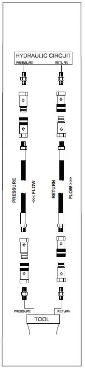
- Make sure the circuit PRESSURE hose (with male quick disconnect) is connected to the “IN” port. The circuit RETURN hose (with female quick disconnect) is connected to the opposite port. Do not reverse circuit flow. This can cause damage to internal seals.
- Always replace hoses, couplings and other parts with replacement parts recommended by STANLEY. Supply hoses must have a minimum working pressure rating of 2500 psi/172 bar.
- Do not exceed the rated flow. Rapid failure of the internal seals may result. See Specifications in this manual for correct flow rate and model number.
- Always keep critical tool markings, such as warning stickers and tags, legible.
- Keep tool bit sharp for maximum drilling performance. Make sure that tool bits are not chipped or rounded on the striking end.
- Never operate a hammer drill without a tool bit or without holding it against the work surface.
- Tool repair should be performed by experienced personnel only.
- Make certain that the recommended relief valves are installed in the pressure side of the system.
- Do not use the tool for applications for which it was not intended.
TROUBLESHOOTING
| PROBLEM | CAUSE | REMEDY |
| Tool does not run. | Power unit not functioning. | Check power unit for proper flow and pressure (7-9 GPM/26-34 LPM, 1500-2000 psi/105–140 bar) |
| Couplers or hoses blocked. | Remove restriction. | |
| Pressure and return line hoses reversed at ports. | Be sure hoses are connected to their proper ports. | |
| Mechanical failure of piston or automatic valve. | Disassemble breaker and inspect for damaged parts. | |
| Tool does not drill effectively. | Power unit not functioning. | Check power unit for proper flow and pressure (7-9 GPM/26-34 LPM, 1500-2000 psi/105-140 bar) |
| Couplers or hoses blocked. | Remove restriction. | |
| Low accumulator charge (pressure hose will pulse more than normal). | Recharge accumulator. Replace diaphragm if charge loss continues. | |
| Fluid too hot (above 140°F/60°C). | Provide cooler to maintain proper fluid temperature (130°F/55°C). | |
| Insufficient air or water. | 20 cfm minimum. | |
| Tool operates slow. | Low GPM supply from power unit. | Check power unit for proper flow (7-9 GPM/26-34 LPM). |
| High back-pressure. | Check hydraulic system for excessive back-pressure (over 250 psi/17 bar). | |
| Couplers or hoses blocked. | Remove restriction. | |
| Orifice plug blocked. | Remove restriction. | |
| Fluid too hot (above 140°F/60°C) or too cold (below 60°F/16°C). | Check power unit for proper fluid temperature. Bypass cooler to warm the fluid or provide cooler to maintain proper temperature. | |
| Relief valve set too low. | Adjust relief valve to 2100–2250 psi/145-155 bar. | |
| Tool gets hot. | Hot fluid going through tool. | Check power unit. Be sure flow rate is not too high causing part of the fluid to go through the relief valve. Provide cooler to maintain proper fluid temperature (140°F/60°C max). Check the relief valve setting. |
| Fluid leakage on drill steel. | Lower piston or drive hex seal failure. | Replace seals. |
| Fluid leakage through charge valve cap. | Upper piston seal failure, accumulator O-ring failure or accumulator charge loss or failure. | Replace seals, recharge or replace accumulator diaphragm. |
| Fluid leakage around trigger. | Valve spool seal failure. | Replace seals. |
| Low rotation torque. | Motor not completely broken in. | Continue operation to break in motor. |
| Excessive oil temperature causes operating pressure loss. | Provide cooler to maintain oil temperature (under 140°F). | |
| Damage to motor clearances. | Repair as required. | |
| Insufficient air or water. | 20 cfm minimum. | |
| Mechanical binding during drilling. | Take care to guide drill straight. |
MAINTENANCE
ACCUMULATOR TESTING PROCEDURE
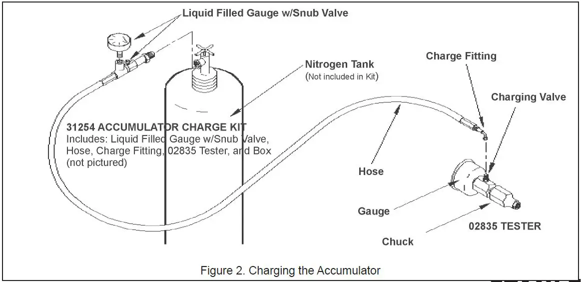
To check or charge the accumulator the following equipment is required:
31254 Charge Kit: which includes the following:
- Accumulator Tester (Part Number 02835).
- Charging Assembly (P/N 15304) Includes a liquid filled gauge w/snub valve, hose and charge fitting.
- NITROGEN bottle with a 800 psi/56 bar minimum charge. (Not included in 31254 Charge Kit.)
- Remove the valve cap assembly from the sinker drill.
- Remove the protective cap and loosen the 5/8-inch hex locking nut on the tool charging valve 1-1/2 turns.
- Holding the chuck end of Accumulator Tester (P/N 02835) turn the gauge fully counterclockwise to ensure that the stem inside the chuck is completely retracted.
- Thread the tester onto the accumulator charging valve. Do not advance the gauge-end into the chuck-end. Turn as a unit. Seat the chuck on the accumulator charging valve and hand tighten only.
- Advance the valve stem of the tester by turning the gauge-end clockwise until a pressure is read on the gauge (charge pressure should be 600-700 psi/42-48 bar).
- If pressure is OK unscrew the gauge-end from the chuck to retract the stem, then unscrew the entire tester assembly from the accumulator charging valve. If pressure is low, charge the accumulator as described in the following procedure.

- Tighten the 5/8-inch hex locking nut on the tool charging valve. Be careful not to overtighten. Install the protective cap and valve cap assembly.
ACCUMULATOR CHARGING
- Perform steps 1 through 4 of the accumulator testing procedure above.
- Connect the chuck of the charging assembly to the charging valve on the accumulator tester or, if preferred, remove the tester from the charging valve and connect the charging assembly chuck directly to the charging valve.
- Adjust the regulator to the charging pressure of 600 psi/42 bar.
Note: It may be necessary to set the gauge at 650-700 psi/45-48 bar to overcome any pressure drop through the charging system. - Open the valve on the charging assembly hose.
- When the accumulator is fully charged close the valve on the charging assembly hose and remove the charging assembly chuck from the accumulator tester or tool charging valve.
- If the accumulator tester has been used, be sure to turn the gauge-end fully counterclockwise before removing the tester from the charging valve of the tool.
- Tighten the 5/8-inch hex locking nut on the tool charging valve and replace the protective cap.
- Replace the valve cap assembly.
UNDERWATER MODEL MAINTENANCE
After each use, the movable portions of the tool that were exposed to water should be flushed with a water displacing oil, such as WD40™. Remove water and debris as follows:
- Turn the tool upside down (without the tool bit) and spray oil through the drive hex and displace any remaining water in the lower cavity.
- Dip or spray the entire tool.
- Cycle the tool hydraulically several times before storing away.
GENERAL SERVICE NOTES
- If the breaker is repainted after servicing, be sure to mask off the vent in the valve cap assembly. Do not allow paint to enter the IN and OUT ports or the bore of the foot assembly.
- If the handle grips need to be replaced.
- Remove the old grips and clean the handle.
- Wash the new grips and the handle clean and dry, simply push or drive the grips on. DO NOT lubricate the parts. The grips will not be secure on the handle if any grease or oil is used.
SPECIFICATIONS
- Shank Size (SK58110 Air, SK58120 Water, SK58310 UW Air): 4-1/4 in. × 1 in. Hex
- Shank Size (SK58130 Air): 4-1/4 in. × 7/8 in. Hex
- Pressure Range: 1500–2000 psi/105–140 bar
- Flow Range: 7-9 GPM / 26-34 LPM
- Optimum Flow: 8 GPM / 30 LPM
- Maximum Back Pressure: 250 psi/17 bar
- Connect Size & Type: 3/8 in. Male Pipe Adapter
- Weight: 67 lbs / 30 kg
- Length: 26 in. / 66 cm
- Width: 18 in. / 46 cm
- Hose Whips: Included
- Port Size: -8 SAE O-ring
- Air Supply: Minimum 30 cfm @ 120 psi
VIBRATION DECLARATION
SK58310 MODELS
DECLARED VIBRATION EMISSION VALUE IN ACCORDANCE WITH ISO-28927-10 2011, EN 12096
- MEASURED VIBRATION EMISSION VALUE: 3-AXIS: 17.7 M/SEC²
- UNCERTAINTY: K: 1.4 M/SEC²
- MEASURED VIBRATION EMISSION VALUE WITH UNCERTAINTY: 3-AXIS: 19.1 M/SEC²
- MEASURED VIBRATION EMISSION VALUE: Z-AXIS: 16.0 M/SEC²
- UNCERTAINTY: K: 1.2 M/SEC²
- MEASURED VIBRATION EMISSION VALUE WITH UNCERTAINTY: Z-AXIS: 17.2 M/SEC²
ACCESSORIES
DRILL STEELS FOR USE WITH AIR
- 1 in. Hex × 4-1/4 in. H Thread, 24 in. / 61 cm UC: 05170
- 1 in. Hex × 4-1/4 in. H Thread, 36 in. / 91 cm UC: 04915
- 1 in. Hex × 4-1/4 in. H Thread, 48 in. / 122 cm UC: 05171
- 7/8 in. Hex × 4-1/4 in. H Thread, 24 in. / 61 cm UC: 05174
CARBIDE ROCK BITS FOR USE WITH AIR (SHOULDER DESIGN)
- 1-3/8 in. Diameter H Thread: 05177
- 1-1/2 in. Diameter H Thread: 05178
UC denotes dimension measured from bottom tip of tool to bottom surface of collar.
SERVICE TOOLS
- O-ring Tool Kit: 04337
- Accumulator Disassembly Tool: 05508
- Accumulator Cylinder Puller: 05640
- Split Rings: 04908
- Flow Sleeve Removal Tube: 04910
- Bearing Installation Tool: 05044
- Bearing Installation Tool: 05061
- Latch Removal Tool: 05045
- Latch Installation Tool: 05879
- Collet, 7/8 in: 05871
- Latch Installation Tool: 05062
- Flow Sleeve Kit: 74397
SK58 PARTS ILLUSTRATION
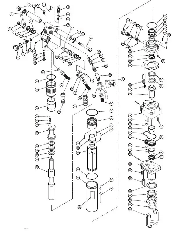
SK58 PARTS LIST
| ITEM | PART NO. | QTY | DESCRIPTION |
| 1 | 04763 | 1 | AIR TUBE (SK58110/SK58130/SK58310 ONLY) |
| 04965 | 1 | WATER TUBE (SK58120 ONLY) | |
| 2 | 07064 | 1 | VENT PLUG |
| 3 | 04964 | 2 | HANDLE GRIP ASSEMBLY |
| 4 | 01714 | 1 | NUT HEAVY HEX JAM |
| 5 | 04786 | 2 | WASHER |
| 6 | 04794 | 1 | O-RING * |
| 7 | 04147 | 1 | LOCKNUT |
| 8 | 04718 | 1 | VALVE LEVER |
| 9 | 04902 | 1 | RETAINING RING |
| 10 | 04751 | 1 | WASHER |
| 11 | 04793 | 1 | KAP SEAL * |
| 12 | 04775 | 1 | CHARGE VALVE CAP |
| 13 | 04052 | 1 | O-RING * |
| 14 | 04051 | 1 | CHARGING VALVE (INCLUDES ITEM 15) |
| 17 | 00955 | 1 | PIPE PLUG |
| 18 | 01411 | 1 | O-RING * |
| 19 | 04772 | 1 | ORIFICE PLUG |
| 20 | 01605 | 2 | O-RING * |
| 21 | 04054 | 3 | O-RING * |
| 22 | 04060 | 1 | ACCUMULATOR CYLINDER |
| 23 | 04059 | 1 | ACCUMULATOR DIAPHRAGM |
| 24 | 04779 | 1 | ACCUMULATOR CHAMBER |
| 25 | 04780 | 1 | BACK UP WASHER |
| 26 | 04386 | 1 | CUP SEAL * |
| 27 | 04750 | 1 | WASHER |
| 28 | 06268 | 1 | TUBE SEAL (SK58120 ONLY) * |
| 29 | 04734 | 1 | PISTON (SK58110 / SK58130) |
| 06265 | 1 | PISTON (SK58120 / SK58310) | |
| 30 | 04068 | 1 | FLOW SLEEVE TUBE |
| 31 | 07889 | 1 | FLOW SLEEVE (SEE NOTE PAGE 19) |
| 32 | 04065 | 1 | AUTOMATIC VALVE |
| 33 | 07890 | 1 | ROLL PIN |
| 34 | 01652 | 2 | PIGTAIL HOSE ASSEMBLY |
| 35 | 04781 | 1 | INLET FLANGE |
| 36 | 02688 | 2 | CAPSCREW |
| 38 | 02003 | 1 | O-RING* |
| 39 | 04771 | 1 | WASHER |
| 40 | 04791 | 1 | KAP SEAL * |
| 41 | 04795 | 1 | O-RING * |
| 42 | 04777 | 1 | THROTTLE VALVE |
| 43 | 04778 | 1 | BLOWER TUBE NUT |
| 44 | 00016 | 1 | O-RING * |
| 45 | 00175 | 1 | O-RING * |
| 46 | 04660 | 1 | HOUSING |
| 47 | 00772 | 1 | KEY |
| 48 | 07291 | 1 | MODIFIED CAPSCREW |
| 49 | 04512 | 1 | RETAINING RING |
| 50 | 04764 | 1 | SWIVEL FITTING |
| 51 | 00106 | 1 | O-RING * |
| 52 | 04765 | 1 | INLET SWIVEL BODY |
| 53 | 04767 | 1 | STREET ELBOW 45° |
| 54 | 05202 | 1 | VALVE-AIR ONLY (SK58110/SK58130/SK58310 ONLY) |
| 55 | 04801 | 1 | HOSE ASSEMBLY |
| 56 | 04066 | 1 | AUTOMATIC VALVE BODY |
| 57 | 04571 | 2 | PUSH PIN |
| 58 | 04067 | 4 | PUSH PIN |
| 59 | 03786 | 1 | GPM STICKER |
| 60 | 05152 | 1 | STANLEY STICKER |
| 61 | 04721 | 1 | LATCH CASTING |
| 62 | 04761 | 1 | RETAINING RING |
| 63 | 04759 | 1 | SPRING BACK-UP |
| 64 | 04758 | 1 | COIL SPRING |
| 65 | 04756 | 1 | LATCH WASHER |
| 66 | 04075 | 4 | SIDE ROD NUT |
| 67 | 01217 | 2 | CAPSCREW |
| 68 | 04748 | 1 | MOTOR PLATE |
| 69 | 00783 | 1 | PIPE PLUG |
| 70 | 04788 | 2 | DU BEARING |
| 71 | 03826 | 2 | DU BEARING |
| 72 | 04033 | 1 | IDLER GEAR |
| 73 | 01277 | 1 | O-RING * |
| 74 | 00713 | 2 | DOWEL PIN |
| 75 | 04744 | 1 | DRIVE MOTOR CHAMBER |
| 76 | 04784 | 1 | DRIVE HEX (SK58110 ONLY) |
| 06267 | 1 | DRIVE HEX (SK58120/SK58310 ONLY) | |
| 05195 | 1 | DRIVE HEX (SK58130 ONLY) | |
| 77 | 04787 | 1 | WOODDRUFF KEY |
| 78 | 04373 | 4 | SIDE ROD |
| 79 | 04774 | 1 | GASKET * |
| 80 | 23395 | 2 | QUAD RING * |
| 81 | 23399 | 2 | BACK-UP RING * |
| 82 | 04769 | 1 | DRIVE MOTOR CONTROL BLOCK (SK58110/SK58130/SK58310 ONLY) |
| 06266 | 1 | DRIVE MOTOR CONTROL BLOCK (SK58120 ONLY) | |
| 83 | 00634 | 2 | NYLON CAP LOCK |
| 84 | 01362 | 1 | O-RING * |
| 85 | 01605 | 1 | O-RING * |
| 86 | 18643 | 1 | SETSCREW |
| 87 | 04753 | 1 | MOTOR CONTROL KNOB |
| 88 | 04773 | 1 | VALVE GUIDE |
| 89 | 04783 | 1 | MOTOR CONTROL VALVE |
| 90 | 04073 | 1 | O-RING * |
| 91 | 30890 | 1 | ROD SEAL * |
| 92 | 04755 | 1 | SEAL WASHER |
| 93 | 04790 | 1 | CUP SEAL * |
| 94 | 03009 | 1 | ROLL PIN |
| 95 | 02688 | 1 | HSHCS |
| 96 | 03047 | 2 | ROLL PIN |
| 97 | 04754 | 1 | THRUST BACK-UP WASHER |
| 98 | 04789 | 1 | THRUST WASHER |
| 99 | 04752 | 1 | DRIVE GEAR |
| 101 | 00026 | 2 | O-RING * |
| 102 | 04776 | 1 | TUBE CONNECTOR |
| 103 | 04796 | 1 | NAME TAG |
| 104 | 04768 | 1 | WATER VALVE (SK58120 ONLY) |
| 105 | 03972 | 1 | COUPLER, FEMALE |
| 106 | 03973 | 1 | COUPLER, MALE |
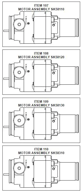
| 107 | 30646 | 1 | MOTOR ASSEMBLY SK58110 |
| 108 | 30647 | 1 | MOTOR ASSEMBLY SK58120 |
| 109 | 30648 | 1 | MOTOR ASSEMBLY SK58130 |
| 110 | 30666 | 1 | MOTOR ASSEMBLY SK58310 |
| SK1 | 04805 | 1 | SEAL KIT (INCLUDES ITEMS 6, 11, 13, 18, 20-21, 26, 28, 37, 38, 40, 41, 44, 45, 51, 73, 79-81, 84, 85, 90, 91, 93, 100 & 101) |
| KT1 | 74397 | 1 | FLOW SLEEVE KIT (INCLUDES ITEMS 21, 31, 58 & 90) |
- SK58110 – 1 INCH × 4-1/4 HEX SHANK AIR
- SK58120 – 1 INCH × 4-1/4 HEX SHANK WATER
- SK58130 – 7/8 INCH × 4-1/4 HEX SHANK AIR
- SK58310 – 1 INCH × 4-1/4 HEX SHANK AIR, UNDER-WATER USE
Note: Use part number and part name when ordering.
DENOTES PART OF SEAL KIT P/N 04805
Note: There is a flow sleeve kit available
P/N-74397 that includes:
Item # 21 (Qty-2 04054 O-ring)
Item # 58 (qty-4 04067 push pin)
Item # 31 (qty-1 07889 flow sleeve)
Item # 90 (qty-1 04073 O-ring) and inst sheet 74398
UNDERWATER TOOLS DEPTH GUIDELINE
UNDERWATER MODELS ONLY
CAUTION: Do not use hydraulic tools underwater that are not designated as an “underwater” model, or this will result in damage to the tool.
For underwater hydraulic tools the applications are broken down into four quadrants depending on type of tool and method of operation.
The types of tools are percussive and rotational, each with different characteristics allowing for different depth operation. With percussive tools, the nitrogen accumulator PSI must counter the increase in ambient pressure found at lower depths. Since there is a maximum PSI for percussive tools they are limited to certain depths. Rotational tools do not have accumulators and thus are capable of deeper depths.
The methods are broken into diver operated or remote operated vehicle (ROV). ROV’s can reach lower depths and with an onboard hydraulic power source that is depth compensated, can operate hydraulic tools at depths of thousands of feet. ROV operation is still limited to the tool, for example a percussive tool has the same depth limitation whether ROV or diver operated.

OPERATION OVERVIEW
| PERCUSSIVE | ROTATIONAL | |
| DIVER | Tools: Breakers, Hammer Drills and Chipping Hammers | Tools: Grinders, Saws, Chain Saws |
| Max Depth: 500’ – limitations due to accumulator PSI max (increase 40 PSI for every 100’) | Max Depth: 1000′
| |
| ROV | Tools: Breakers, Hammer Drills and Chipping Hammers | Tools: Grinders, Saws, Chain Saws |
Max Depth: 500′
| Max Depth: 1000′
|
| RECOMMENDED HOSE DIAMETERS | ||
| DEPTH (FT) | 8 GPM | 12 GPM |
| 100 | 5/8″ | 5/8″ |
| 300 | 3/4″ | 1″ |
| 600 | 1″ | 1″ |
| 1000 | 1″ | 1-1/4″ |
STANLEY Infrastructure
6430 SE Lake Road
Portland, Oregon 97222 USA
(503) 659-5660 / Fax (503) 652-1780
www.stanleyinfrastructure.com


