
BIC 2200 Series Bidirectional Power Supply with Energy Recycle
BIC 2200 Series
Installation manual

Bidirectional Power Supply
Installation manual
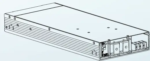
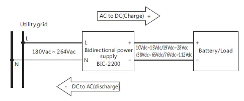
The BIC-2200 is a 2.2KW bidirectional power supply with energy recycle
function. It is fully digital and 1U height designed. Itis designed to control the
power transferred from AC grid to DC and DC to AC grid for energy recycle.
The implementation of a bidirectional power supply of the BIC-2200 allows
battery manufactures to charge the battery from AC grid and recycle the DC
energy back into AC grid in one single unit. With built-in functions such as
active current sharing, remote ON/OFF control and optional CANbus
protocol, the BIC-2200 provides vast design flexibility for battery formation &
test equipment, V2G(Vehicle-to-grid) system, charging station, laser system
and kinetic recovery system.
1. Safety Guidelines
- Risk of electrical shock and energy hazard, all failure should be
examined by a qualified technician. Please do not remove the
case form the bidirectional power supply by yourself. - Please do not install the supply in places with high moisture,
high ambient temperature or under direct sunlight. - The AC voltage range is 180 – 260Vac (47 – 63Hz), please do not
connect the supply to AC gird out of the range. - Fans and ventilation holes must be kept free from any
obstructions. At least 15 cm clearance must be kept when the
adjacent device is a heat source. - Please do not stack any object on the unit.
- The safety protection level of this supply is class I. The “Frame
Ground”( ) of the unit must be well connected to PE (Protective
Earth).
2.Introduction
2.1 Model Encoding
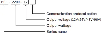
| Type | Communication | Note |
| Blank | None protocol | In stock |
| CAN | CANBus protocol | By request |
2.2 Features
- 1U low profile design
- Full digital design with 93% conversion efficiency for both AC/DC
and DC/AC conversion - Ultrafast switching time between AC/DC and DC/AC of 1ms.
- CB/UL/TUV CB/TUV/UL 62368-1 certified, and design refer to IEC
62477 regulation - Active current sharing up to 11000W(4+1)
- <3% Low THDi in both conversion mod
- Force charging and discharging mode with CANBus command
(Optional) - Complete protections: Anti-islanding protection, AC fail protection,
DC OVP,OLP, OCP, OTP - 5 years warranty
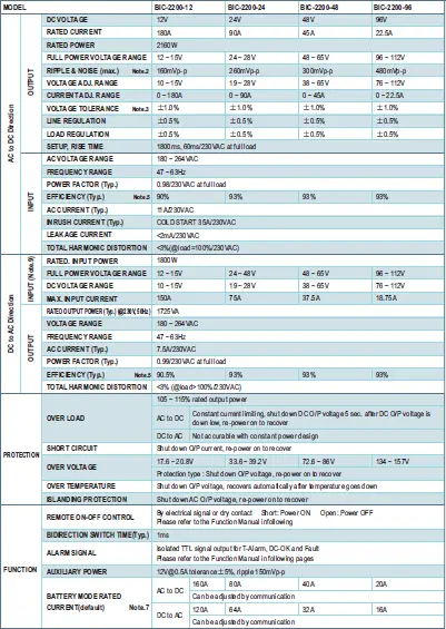
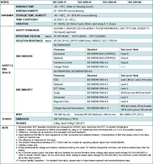
2.3 Specification
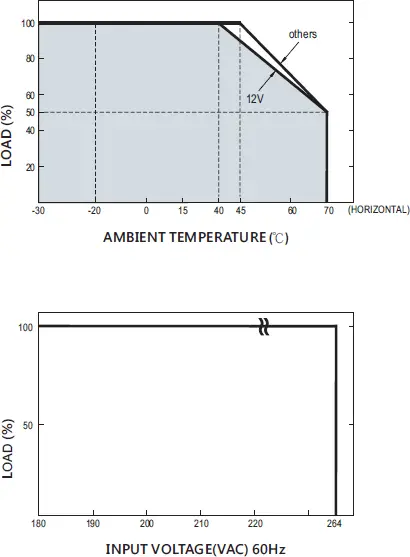
2.4 Derating curve
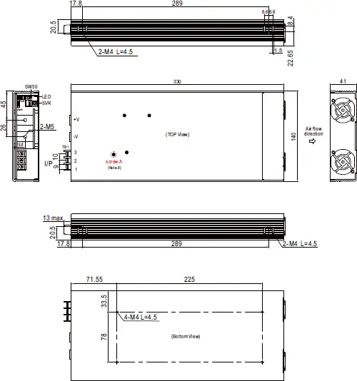
2.5 Mechanical specification
3.Installation & Wiring
3.1 Precautions
- Please make sure the system chassis has sufficient strength to
carry the unit. - In order to ensure the lifespan of the unit, you should refrain from
operating the unit in environment of high dust or moisture. - The bidirectional power supply is designed with built-in DC fans,
please make sure the ventilation is not blocked. There should be
no barriers within 15cm of the ventilating
3.2 Installation Procedures
- Choose the right and suitable cable size for connection between
the BIC-2200 and the loads or batteries. Please refer to 3.3 DC cable
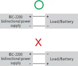
size selection. - Connect the DC positive polarity of the supply to the positive of the
loads/batteries and connect the DC negative polarity of the supply
to the negative of the loads/batteries. Make sure there is no reverse
polarity or short-circuit on the connection.
- Connect the supply to the AC grid, FG to the earth, AC/N to the
neutral and AC/L to the live.
NOTE: The bidirectional power supply i s single-phase
input/output. Please pay attention to the wiring when connecting
the supply to a three-phase system.
3.3 DC Cable Size Selection
Wire connections should be as short as possible and less than
1 meter is highly recommended. Make sure that suitable wires
are chosen based on safety requirement and rating of current.
Small cross section will result in lower efficiency, less output
power and the wires may also become overheated and cause
danger. For selection, please refer to table 3-1.
| AWG | Cross-section Are(mm ) | DC current (A) |
| 8 | 6 | 32A ~ 40A |
| 6 | 10 | 40A ~ 63A |
| 4 | 16 | 63A ~ 80A |
| 2 | 25 | 80A ~ 100A |
| 1 | 30 | 100A ~ 125A |
| — | 35 | 139A |
| — | 50 | 190A |
| — | 60 | 217A |
| — | 80 | 257A |
Table 3-1Wire recommendations
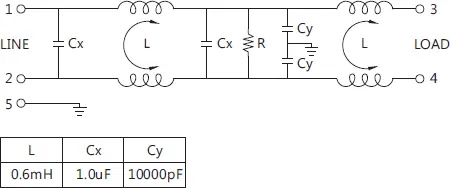
3.4 External filter
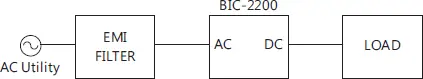
To meet regulations of EMC conducted and radiated emission, adding
an additional EMI filter is needed. Please refer to configuration below
and characteristics for suggested filters.
3.4.1 Configration
3.4.2 Schematic
3.4.3 Minimum insertion loss (In dB at 50Ω system) : Filter model 30DPGS5C
or equivalent
| FREQ. MHz | 0.01 | 0.05 | 0.1 | 0.15 | 0.15 | 1 | 5 | 10 | 30 |
| COM. MODE dB | 2 | 5 | 8 | 10 | 10 | 35 | 55 | 45 | 30 |
| DIF. MODE dB | 4 | 15 | 18 | 18 | 18 | 50 | 40 | 40 | 40 |
4.User Interface
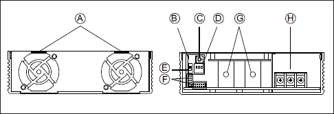
4.1 Panel Description
A. Ventilation holes for fans:
The supply requires suitable ventilation to work properly.
Please make sure there is sufficient ventilation and the lifespan
of the supply can preserved.
B. LED indicator:
Indicate the status of supply and the load condition.
C. SVR:
For DC voltage setting.
D. DIP switch:
For device addressing when using the communication interface.
E. SW50:
Used to stabilize parallel signals when multi-supplies in parallel
connection.
F. Function pins:
They are used for control and monitoring functions. Please refer to 4.3
and 4.4.
G. DC terminals
H. AC terminals
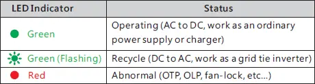
4.2 LED Indicator
The LED indicator is controlled by the microcontroller or the MCU.
The MCU will change color of the indicator according to its operation
status. The indicator lights in constant green when the supply is in
operating mode; The indicator’s flashing in green when the supply is
in recycle mode; The indicator turns red when the supply is in
abnormal conditions or protection mode.
4.3 Pin Assignment of CN46
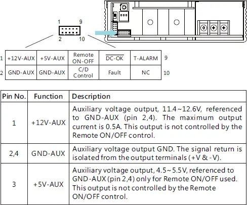
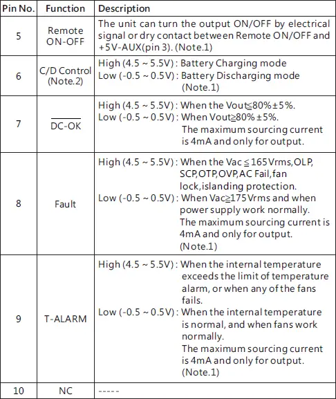
Note 1 : Isolated signal, referenced to GND-AUX.
Note 2 : CANBus model only.
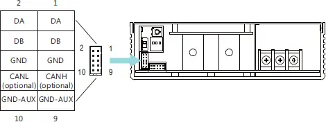
4.4 Pin Assignment of CN47
| Pin No. | Function | Description |
| 1,2 | DA | Differential digital signal for parallel control. (Note.1) |
| 3,4 | DB | |
| 5,6 | GND | Negative output voltage signal. Certain function reference. It can not be connected directly to the load. |
| 7 | CANH (optional) | For CANBus model: Data line used in CANBus interface. (Note.2) |
| 8 | CANL (optional) | For CANBus model: Data line used in CANBus interface. (Note.2) |
| 9,10 | GND-AUX | Auxiliary voltage output GND. The signal return is isolated from the output terminals (+V & -V). |
Note 1 : Non-isolated signal, referenced to GND.
Note 2 : Isolated signal, referenced to GND-AUX.
4.5 Function Description of SW50
Parallel connection of the BIC-2200 is by digital differential signals.
Units in parallel compensate and stabilize their output through the
digital parallel signals. SW50 is a termination resistor which is used
to prevent signal reflections, then increasing communication
quality. For the usage of SW50, please refer to 5.9 Current Sharing.
4.6 Function Description of DIP Switch
Each unit should have their unique and own device address to
communicate over CANBus. Please be aware that: This DIP switch
only takes effect when the communication interface is used. It is not
necessary to set this switch in general use. For details, please refer to
5.10.2 CANBus addressing.
5.Operation
BIC-2200 possesses AC to DC and DC to AC two way conversion functions.
The conversion direction can be automatically detected and controlled by
BIC-2200’s internal firmware or manually switched by users according to
different application requirements. Before entering detailed function
explanation. Please refer to following definitions.
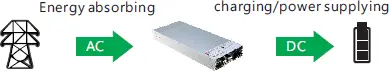
AC to DC (Energy absorbing and charging/ power supplying):
The BIC-2200 converts AC energy from the grid into DC energy for the battery
or the loads. The operation principle is the same as an ordinary power supply
or a charger.
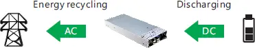
DC to AC (Energy recycling and discharging):
Opposite to the AC to DC conversion, the BIC-2200 converts DC energy from
the battery or loads into AC energy, then feeding back to the grid. AC output
synchronization range is 180Vac~264Vac/47Hz~63Hz, the bidirectional power
supply can work normally as long as the AC gird is within the range.
5.1 Description of Bidirectional Operation
5.1.1 Overview
The output range of the BIC-2200 covers DC: 10V – 112V;
AC: 180 – 264Vac / 47-63Hz, which can be used to applications with
various voltage requirements, such as battery test equipment. To
cope with different application occasions, there are two modes for
selection, bi-direction auto-detect mode and programmable bi-direction
battery mode.
5.1.2 Bi-direction auto-detect mode
This is the default factory setting, AC to DC or DC to AC conversion is
controlled by BIC-2200 automatically according to operation
mechanism below.
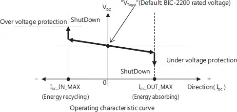
- “Target voltage” is the DC voltage setting of the bidirectional
supply, when the DC end voltage is different from the “target
voltage”, the internal firmware will switch between two conversion
functions of AC to DC or DC to AC. “Target voltage” is adjustable
by the SVR. - When the “target voltage” is higher than the battery voltage or
application equipment voltage, the BIC-2200 operates in AC to
DC conversion. - When the “target voltage” is lower than the battery voltage or
application equipment voltage, the BIC-2200 operates in DC to
AC conversion.
NOTE: During this mode, AC to DC or DC to AC conversion is
judged by the internal firmware. Active control signal (e.g. C/D
control) will not take effect in this mode.
| Condition | Conversion |
| V >V Target DC | AC to DC |
| V >V Target DC | DC to AC |
5.1.3 Bi-direction battery mode
This is an optional mode, which must work with CANBus
communication interface. To activate the mode, please follow
below:
1. Set command SYSTEM_CONFIG(0x00C2) at 0x0003→Activate
CANBus communication mode.
2. Set command BIDIRECTIONAL_CONFIG(0x00C2) at 0x0001→Set
at bi-direction battery mode.
3. Repower on the supply to activate the battery mode
NOTE: For detailed CANBus information, please refer to 5.10
CANBus Protocol
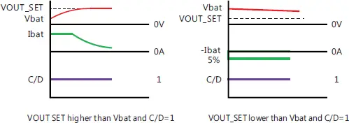
After bi-direction battery mode is activated, users can switch the
supply between AC to DC or DC to AC conversion by CANBus
command (digital) or C/D control (analogy). Please refer to 5.1.3.1
CANBus command (digital) and 5.1.3.2 C/D control (analogy)
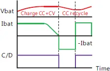
Logic control curve
5.1.3.1 CANBus command (digital)
The users can set the supply in AC to DC (charging) or DC to AC
(discharging) conversion directly through command DIRECTION_CTRL
(0x0100). Command VOUT_SET(0x0020) and IOUT_SET(0x0030) are
used to adjust values of charge voltage and charge current in AC to DC
conversion. Command REVERSE_VOUT_SET(0x0120) REVERSE_
IOUT_SET(0x0130) are used to adjust values of discharge voltage and
discharge current in DC to AC conversion.
| Condition | Conversion |
| DIRECTION_CTRL = 00h | AC to DC(charge) |
| DIRECTION_CTRL = 01h | DC to AC(discharge) |
NOTE: Please refer to 5.10.4 CANBus value range and tolerance for
detailed information about adjustable ranges of VOUT_SET, IOUT_SET,
REVERSE_VOUT_SET and REVERSE_IOUT_SET.
5.1.3.2 C/D Control (analogy)
The users also can control AC to DC (charge) or DC to AC (discharge)
conversion via analogy signals.
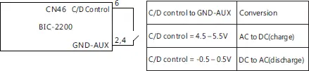
NOTE: Analogy signals cannot be used to adjust parameters of charging
voltage (VOUT_SET)/discharging voltage (REVERSE_VOUT_SET) and
charging current (IOUT_SET)/discharge current (REVERSE_IOUT_SET), but only
control AC to DC or DC to AC conversion.
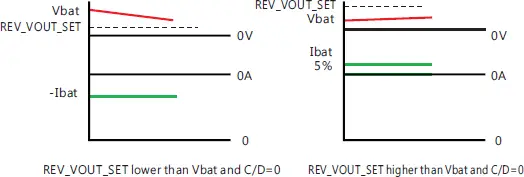
5.1.3.3 Notes on battery mode
In bi-direction battery mode, although users can determine
direction of the conversions on their demand, however if the
setting voltage does not match the actual DC end voltage, AC to
DC (charging) or DC to AC (discharging) conversion may not work
as expected. Here are examples that will cause conversion errors.
- During AC to DC conversion (C/D control = High or
DIRECTION_CTRL = 00h), if battery voltage is higher than
the value of command VOUT_SET (charge voltage), the
BIC-2200 will perform DC to AC conversion instead, but
limiting discharge current at 5% of rated current. If you
want to ensure AC to DC conversion working properly,
please make sure value of command VOUT_ SET is higher
than the battery voltage. - During DC to AC conversion (C/D control =Low or
DIRECTION_CTRL = 01h), if battery voltage is lower than
the value of command VOUT_SET_REV, the BIC-2200 will
perform AC to DC conversion instead, but then limiting
charge current at 5% of rated current. To ensure DC to AC
conversion working properly, please make sure value of
command VOUT_ SET_REV is lower than the battery
voltage.
5.2 Inrush Current Limiting
- Built-in AC inrush current limiting circuit
- Since the inrush current limiting circuit mainly consists of a NTC
thermistor and a relay, inrush current will be much higher than the
specified value if the thermistor in AC side is not allowed sufficient
time to cool down. After turning off the supply, a 10 second cool down
period is recommended before turning on again.
5.3 Power Factor Correction (PFC)
- Built-in active power factor correction (PFC) function, power factor (PF)
will be 0.95 or better at full load condition in AC to DC or DC to AC
conversion. PF will be less than 0.95 if it is not at full load condition
during AC to DC or DC to AC conversion.
5.4 Fan Speed control
- Built-in fan speed control circuit, fan speed changes automatically
depending on internal temperature.
5.5 Fault Signal
- Fault signal is used to inform application equipment that whether it is
energy recyclable. When it is OLP, SCP or OTP, BIC-2200 will send a high
level of fault signal 100ms in advance to notify the application before
shutting down the supply. A fault signal will send out at the same time of
shutting down operation in the reset of protection (e.g. AC fail). - Maximum output current 4mA.
5.6 (DC-OK) Signal
- Built-in DC output voltage detection circuit.
- Maximum output current 4mA.
5.7 Remote Control
- Built-in remote ON/OFF control circuit, which is used to turn on/off the
supply. - Please be aware that “remote ON/OFF and “+5V-AUX” on CN46 should
be linked together to allow the unit to operate normally; if kept open,
there will be no output. - Maximum input voltage 5.5V.
5.8 Auxiliary Output
- Built-in 12V/0.5A auxiliary output
5.9 Parallel Operation
BIC-2200 has the built-in active current sharing function and can be
connected in parallel, up to 5 units, to provide higher output power as
exhibited below:
- The power supplies should be paralleled using short and large diameter
wiring and then connected to the load. - In parallel connection, power supply with the highest output voltage will
be the master unit and its Vout will be the DC bus voltage. - The total output current must not exceed the value determined by the
following equation:
Maximum output current at parallel operation=(Rated current per unit)
x (Number of unit) x 0.95 - When the total output current is less than 5% of the total rated current,
or say (5% of Rated current per unit) x (Number of unit) the current
shared among units may not be balanced. - Under parallel operation ripple of the output voltage may be higher than
the SPEC at light load condition, It will go back to normal ripple level
once the output load is more than 5%. - CN47/SW50 Function pin connection
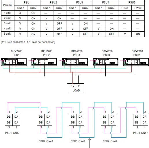
If the lines of CN47 are too long, they should
be twisted in pairs to avoid the noise.
◎ DA、DB Connected mutually in parallel
5.10 CANBus Protocol
CANBus communication interface provides control and monitoring
functions. It is helpful when users intent to modify the parameters
remotely. Users can read and write the parameters through the bus, which
includes bi-directional battery mode switch, ON/OFF, charge voltage/
current, discharge voltage/ current, temperature, etc.
5.10.1 CAN Bus Specification
- Physical layer specification
This protocol follows CAN ISO-11898 with Baud rate of
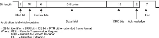
250Kbps. - Data Frame
This protocol utilizes Extended CAN 29-bit identifier frame
format or CAN 2.0B.
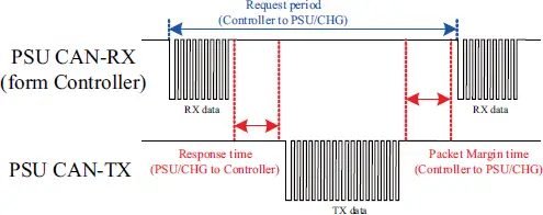
- Communication Timing Min. request period (Controller to BIC-2200): 20mSec
Max. response time (BIC-2200 to Controller): 5mSec
Min. packet margin time (Controller to BIC-2200): 5mSec
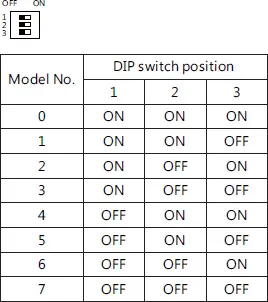
5.10.2 CANBus Addressing
Each BIC-2200 unit should have their unique and own device
address to communicate over the CANBus. PIN 1 – PIN 3 of the DIP
switch allows users to designate an address for their supply units
(with maximum of 8 addresses). Please refer to below for the
detailed setup advice.
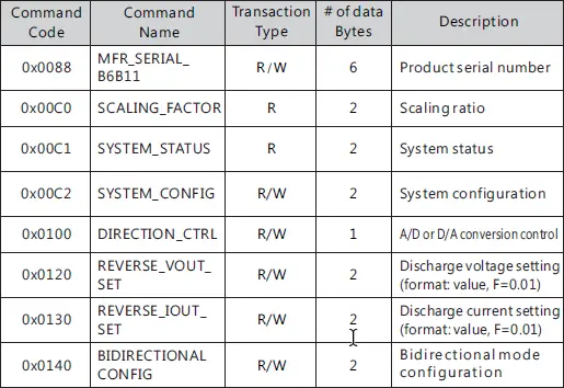
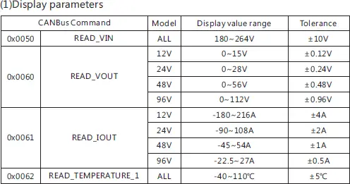
5.10.3 CANBus command list
| Command Code | Command Name | Transaction Type | # of data Bytes | Description |
| 0x0000 | OPERATION | R/W | 1 | Remote ON/OFF control |
| 0x0020 | VOUT_SET | R/W | 2 | Charge voltage setting (format: value, F=0.01) |
| 0x0030 | IOUT_SET | R/W | 2 | Charge current setting (format: value, F=0.01) |
| 0x0050 | READ_VIN | R | 2 | Summary status reporting |
| 0x0040 | FAULT_STATUS | R | 2 | AC voltage reading value (format: value, F=0.1) |
| 0x0060 | READ_VOUT | R | 2 | DC voltage reading value Note. i(format: value, F=0.01) |
| 0x0061 | READ_IOUT | R | 2 | DC current reading value (format: value, F=0.01) |
| 0x0062 | READ_ TEMPERATURE_1 | R | 6 | Internal ambient temperature (format: value, F=0.1) |
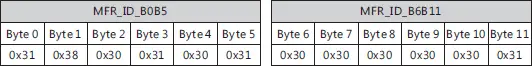
| 0x0080 | MFR_ID_B0B5 | R | 6 | Manufacturer’s name |
| 0x0081 | MFR_ID_B6B11 | R | 6 | Manufacturer’s name |
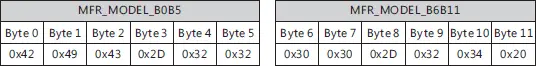
| 0x0082 | MFR_MODEL_B0B5 | R | 6 | Manufacturer’s model name |
| 0x0083 | MFR_MODEL_ B6B11 | R | 6 | Manufacturer’s model name |
| 0x0084 | MFR_REVISION_ B0B5 | R | 6 | Firmware revision |
| 0x0085 | MFR_LOCATION_ B0B2 | R/W | 3 | Manufacturer’s factory location |
| 0x0086 | MFR_DATE_B0B5 | R/W | 6 | Manufacturer’s date |
| 0x0087 | MFR_SERIAL_B0B5 | R/W | 6 | Product serial number |
Note :
The conversion of setting and reading values is defined as following:
Actual value = Communication reading value × Factor (F value). Among them,
Factor needs to refer to the definition of SCALING_FACTOR in each model list.
EX: VDC_real (actual DC voltage) = READ_VOUT x Factor.
If the Factor of READ_VOUT of a certain model is 0.01, the communication reading
value is 0x0960 (hexadecimal) → 2400 (decimal), then VDC_real = 2400 × 0.01 =
24.00V.
Message ID definition:
| Description | Message ID |
| BIC-2200 to controller Message ID | 0x000C02XX |
| Controller to BIC-2200 Message ID | 0x000C03XX |
| Controller broadcasts to BIC-2200Message ID | 0x000C03FF |
Note : XX means the address of BIC-2200 ( which can be assigned by the DIP switch,
range from 0x00 ~ 0x07)
FAULT_STATUS:
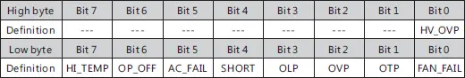
Low byte :
Bit 0 FAN_FAIL:Fan locked flag
0=Fan working normally
1=Fan locked
Bit 1 OTP:Over temperature protection
0=Internal temperature normal
1=Internal temperature abnormal
Bit 2 OVP:DC over voltage protection
0=DC voltage normal
1=DC over voltage protected
Bit 3 OLP:DC over current protection
0=DC current normal
1=DC over current protected
Bit 4 SHORT:Short circuit protection
0=Shorted circuit do not exist
1=Shorted circuit protected
Bit 5 AC_FAIL:AC abnormal flag
0=AC range normal
1=AC range abnormal
Bit6 OP_OFF:DC status
0=DC turned on
1=DC turned off
Bit7 HI_TEMP:Internal high temperature protection
0=Internal temperature normal
1=Internal temperature abnormal
High byte :
Bit 0 HV_OVP:HV over voltage protection
0=HV voltage normal
1=HV over voltage protected
MFR_ID_B0B5 is the first 6 codes of the manufacturer’s name (ASCII);
MFR_ID_B6B11 is the last 6 codes of the manufacturer’s name (ASCII)
EX: manufacturer’s name is MEANWELL → MFR_ID_B0B5 is MEANWE;
MFR_ID_B6B11 is LL
MFR_MODEL_B0B5 is the first 6 codes of the manufacturer’s model name
(ASCII); MFR_MODEL_B6B11 is the last 6 codes of the manufacturer’s model
name (ASCII);
EX: Model name is BIC-2200-24→MFR_MODEL_B0B5 is BIC-22;
MFR_MODEL_B6B11 is 00-24
MFR_REVISION_B0B5 is the firmware revision (hexadecimal). A range of 0x00
(R00.0)~0xFE (R25.4) represents the firmware version of an MCU; 0xFF
represents no MCU existed
EX: The supply has two MCUs, the firmware version of the MCU number 1 is
version R25.4 (0xFE), the MCU number 2 is version R10.5 (0x69)
![]()
MFR_DATE_B0B5 is manufacture date (ASCII)
EX: MFR_DATE_B0B5 is 180101, meaning 2018/01/01
![]()
MFR_SERIAL_B0B5 and MFR_SERIAL_B6B11 are defined as manufacture
date and manufacture serial number (ASCII)
EX: The first unit manufactured on 2018/01/01→MFR_SERIAL_B0B5:
180101;MFR_SERIAL_B6B11: 000001
SCALING_FACTOR :
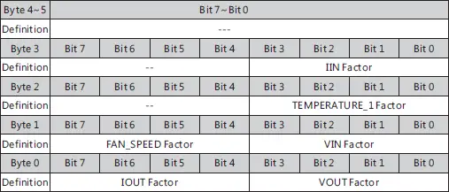
byte 0 :
Bit 0 : 3 VOUT Factor:The Factor of DC voltage
0x0=DC voltage relevant commands not supported
0x4=0.001
0x5=0.01
0x6=0.1
0x7=1.0
0x8=10
0x9=100
Bit 4 : 7 IOUT Factor:The Factor of DC current
0x0=DC current relevant commands not supported
0x4=0.001
0x5=0.01
0x6=0.1
0x7=1.0
0x8=10
0x9=100
byte 1 :
Bit 0 : 3 VIN Factor:The Factor of AC voltage
0x0=AC voltage relevant commands not supported
0x4=0.001
0x5=0.01
0x6=0.1
0x7=1.0
0x8=10
0x9=100
Bit 4 : 7 FAN_SPEED Factor:The Factor of fan speed
0x0=Fan speed relevant commands not supported
0x4=0.001
0x5=0.01
0x6=0.1
0x7=1.0
0x8=10
0x9=100
byte 2 :
Bit 0 : 3 TEMPERATURE_1 Factor:The Factor of internal ambient
temperature
0x0=internal ambient temperature relevant commands not
supported
0x4=0.001
0x5=0.01
0x6=0.1
0x7=1.0
0x8=10
0x9=100
byte 3 :
Bit 0 : 3 IIN FactorThe Factor of AC current
0x0=AC current relevant commands not supported
0x4=0.001
0x5=0.01
0x6=0.1
0x7=1.0
0x8=10
0x9=100
0xA~0xF= Reserved
SYSTEM_STATUS:
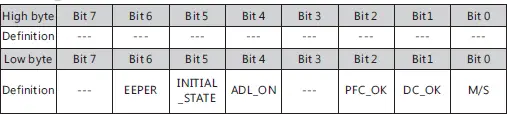
Low byte :
Bit 0 M/S:parallel mode status
0=Current device is Slave
1=Current device is Master
Bit 1 DC_OK:Secondary DD output voltage status
0=Secondary DD output voltage status TOO LOW
1=Secondary DD output voltage status NORMAL
Bit 2 PFC_OK:Primary PFC status
0=Primary PFC OFF or abnormal
1=Primary PFC ON normally
Bit 4ADL_ON:Active dummy load control status
0 = Active dummy load off/function not supported
1= Active dummy load on
Bit 5 INITIAL_STATE: Device initialized status
0=In initialization status
1=NOT in initialization status
Bit6 EEPER:EEPROM data access error
0=EEPROM data access normal
1=EEPROM data access error
※ When an EEPROM data access error occurs, the supply shuts
down and then entering protection mode with the LED indicator off.
It only can be recovered after the EEPROM error condition is
resolved.
SYSTEM_CONFIG :
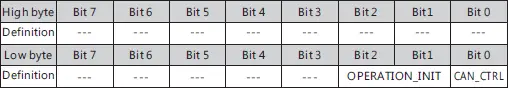
Low byte :
Bit 0 CAN_CTRL:CANBus communication control status
0=The output voltage/current defined by control over SVR
1=The output voltage, current, ON/OFF control defined by control
over CANBus (VOUT_SET, IOUT_SET, OPERATION)
Bit1:2 OPERATION_INIT:Pre-set value of power on operation command
0b00=Power OFF, pre-set 0x00(OFF)
0b01=Power ON, pre-set0x01(ON)
0b10=Pre-set is previous set value
0b11=not used, reserved
BIDIR_CONFIG:
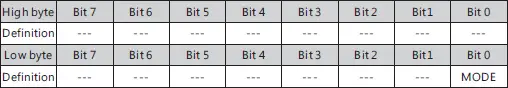
Low byte :
Bit 0 MODE: Bidirectional mode configuration
0=Bi-direction auto-detect mode. DIR_CTRL and C/D control
(analogy) UN-controllable.
1=Bi-direction battery mode. DIR_CTRL and C/D control (analogy)
controllable
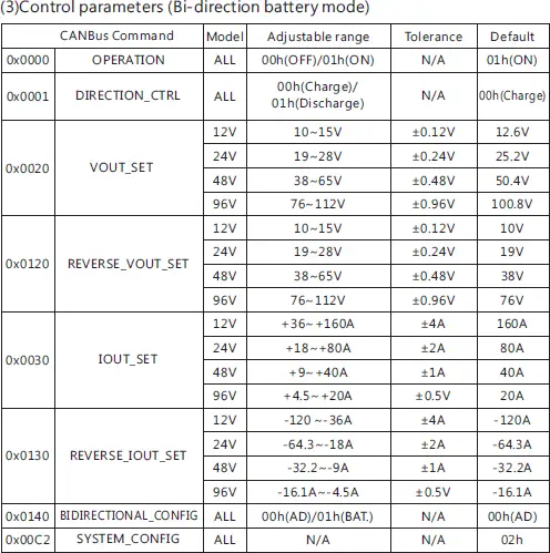
5.10.4 CANBus value range and tolerance:
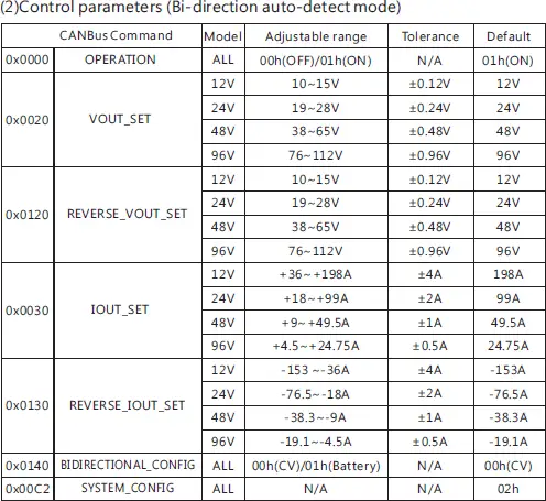
5.11 Restore Factory Default Setting
Users could set the device into factory default by following steps
( command 0x0000, 0x0020, 0x0120, 0x0030, 0x0130, 0x0140, 0x00C2):
(1) Set all DIP switch positions (device address) to ON
(2) Power on in REMOTE OFF mode (no output at this step)
(3) After power on, in 15 seconds, switch all DIP switch from ON to
OFF and then switch ALL back to ON position.
(4) Green LED will blink 3 times if set successfully
(5) Factory default setting will be restored after re-power on.
DIP switch diagram is as shown below.
6.Protections and Trouble Shooting
6. 1 Protections
6.1.1 Anti-islanding Protections
BIC-2200 is designed to refer to IEC 62116(2008), the supply shuts off
within 2 seconds when AC is cut or abnormal. Please be aware that it is
necessary to install an AC circuit breaker that complies with grid-tie
standard in your country before the supply.
6.1.2 Over Temperature Protection (OTP) and Alarm
Built-in thermal detection circuit, once the internal temperature
exceeds a threshold value, the supply will shut down automatically (the
fans will still be running to cool down the supply). Please switch off the
supply, remove all possible causes and then leave the supply cooling
down to a normal working temperature (approximate 10 minutes – 1
hour) before repower on again.
Maximum output current 4mA.
6.1.3 AC Fail Protection
When AC voltage/frequency is abnormal, BIC-2200 will enter
protection mode to prevent damaging itself or affect quality of the
grid no matter which conversion it is, D/A or A/D. The supply will
restore automatically when AC voltage/frequency back to normal.
6.1.4 Short Circuit Protection
When there is short circuit at AC/DC end of BIC-2200, the supply will
enter protection mode and shut down. Repower on to restore after
short-circuit condition is resolved.
6.1.5 Over Current Protection
In AC to DC conversion, when the load current exceeds 110%±5%
of the rated current, protection mode will be triggered. Repower
on to restore after over-current condition is resolved.
6.1.6 DC Over Voltage Protection
When the DC end voltage is too high, the DC over-voltage
protection circuit will be triggered. Repower on to restore after
over-voltage condition is resolved.
6.2 Trouble Shooting
| Failure State | Possible Cause | Suggested Solution |
| The supply is not working | Remote OFF | Make sure remote ON/OFF is connected to +5V |
| AC/DC or DC/AC conve r sion i s incorrect | The setting voltage doesn’t match actual DC end voltage | If it is bi-direction auto-detect mode, please refer to 5.1.2. If it is bi-direction battery mode, please refer to 5.1.3.3 |
LED shows abnormal indication | The ambient temperature too high | Re-start the supply after temperature dropped back |
| DC load current too high | Re-start the supply after reducing DC load current | |
| AC voltage/frequency abnormal | Re-start the supply after AC voltage/frequency is within a normal range | |
| Battery or load voltage too high | Re-start the supply after DC end voltage is within a normal range |
If you are unable to clarify the problem you are facing, please contact
MEAN WELL or any of our distributors for repair service.
7.Warranty
This product provides five years warranty under normal usage. Do not replace
parts or any form of modification to the product in order to keep the warranty
effectively.
※ MEAN WELL possesses the right to adjust the content of this manual.
Please refer to the latest version of our manual on our website.
https://www.meanwell.com