
nVent CFS126 BC Beam Clamp and Conduit Clip

Product Information
The product is a BC Beam Clamp and Conduit Clip designed for supporting pipes and conduits. The BC Beam Clamp can be installed on a maximum flange thickness of 1/2 inch and has a static load rating of up to 100lb. The Conduit Clip can fit conduit sizes ranging from 3/8 inch to 2 inches and has different latching holes for different sizes. The product should only be used as indicated in the instruction sheet and should not be used for any purpose other than the purpose for which it was designed.
Product Usage Instructions:
BC Beam Clamp Installation:
- Place the BC Beam Clamp onto the flange with a maximum thickness of 1/2 inch.
- Tighten the Beam Clamp Set Screw to 20 in.-lbs using a torque wrench.
Conduit Clip Installation:
- Select the appropriate latching hole from the sizing chart based on the conduit size being used.
- Fit the conduit into the Conduit Clip.
- Snap the Locking Tab into the desired Latching Hole using
channel lock pliers.
Note: For the 16M Conduit Clip, compress the Bottom Gripping
Tabs prior to installing the 3/4 RIGID and 1 RIGID Conduit.
Warnings
- nVent products should only be used as indicated in nVent product instruction sheets and training materials.
- nVent products must never be used for a purpose other than the purpose for which they were designed or in a manner that exceeds specified load ratings.
- All instructions must be completely followed to ensure proper and safe installation and performance.
- Improper installation, misuse, misapplication, or other failure to completely follow nVent’s instructions and warnings may cause product malfunction, property damage, serious bodily injury, and/or death, and void your warranty.
- Products that are manufactured using spring steel components shall be used only in a non-corrosive indoor environment.
- All pipe supports, hangers, intermediate components, and structural attachments must ONLY be used as described herein and are NEVER to be used for any other purpose.
Technical Support:
For technical support or more information about the product, visit www.nVent.com.
Disclaimer: nVent reserves the right to change specifications
without prior notice.
PRODUCT OVERVIEW
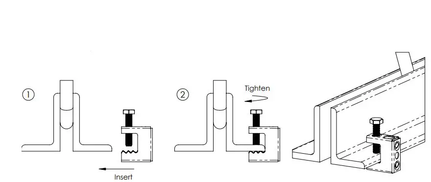
BC Beam Clamp Installation
- Install BC Beam Clamp onto a Maximum Flange Thickness of 1/2″ [13 mm].
- Tighten Beam Clamp Set Screw to 20 in.-lbs. [2.25 N-m]

WARNING:
- nVent products shall be installed and used only as indicated in nVent product instruction sheets and training materials. Instruction sheets are available at www.nVent.com and from your nVent customer service representative.
- nVent products must never be used for a purpose other than the purpose for which they were designed or in a manner that exceeds specified load ratings.
- All instructions must be completely followed to ensure proper and safe installation and performance.
- Improper installation, misuse, misapplication or other failure to completely follow nVent’s instructions and warnings may cause product malfunction, property damage, serious bodily injury and/or death, and void your warranty.
- Products that are manufactured using spring steel components shall be used only in a non-corrosive indoor environment.
- All pipe supports, hangers, intermediate components and structural attachments must ONLY be used as described herein and are NEVER to be used for any other purpose.
NOTE: All load ratings are for static conditions and do not account for dynamic loading such as wind, water or seismic loads, unless otherwise noted. The customer is responsible for:
- a. Conformance to all governing codes.
- b. The integrity of structures to which the products are attached, including their capability of safely accepting the loads imposed, as evaluated by a qualified engineer.
- c. Using appropriate industry standard hardware as noted above.
SAFETY INSTRUCTIONS:
All governing codes and regulations and those required by the job site must be observed.
Always use appropriate safety equipment such as eye protection, hard hat, and gloves as appropriate to the application.
nVent, nVent CADDY, nVent ERICO Cadweld, nVent ERICO Critec, nVent ERICO, nVent ERIFLEX, and nVent LENTON are owned by nVent or its global affiliates. All other trademarks are the property of their respective owners. nVent reserves the right to change specifications without prior notice.
INSTRUCTION SHEET
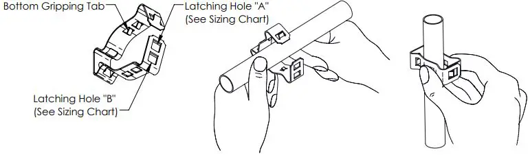
Conduit Clip Installation
- Select the appropriate Latching Hole from Sizing Chart Fit Conduit into Conduit Clip
- For the 16M, compress the Bottom Gripping Tabs prior to installing the 3/4″ RIGID and 1″ RIGID Conduit
- By Hand or with Channel Lock Pliers, snap Locking Tab into the desired Latching Hole

Global Part Number Local Part Number Sizing Chart Latch “A” Latch “B” 6M 170790 3/8″ EMT, IMC & RIGID N/A 812M 177130 3/4″ EMT, IMC & RIGID 1/2″ EMT, IMC & RIGID 16M 170100 1″ EMT, IMC & RIGID 3/4″ EMT, IMC & RIGID 20M 170110 1-1/4″ RIGID 1-1/4″ EMT & IMC 24M 170120 1-1/2″ RIGID 1-1/2″ EMT & IMC 32M 170130 2″ RIGID 2″ EMT & IMC For Thread Impression Conduit Clip’s, select the appropriate Latching Hole from the Sizing Chart based on the Conduit Size being used
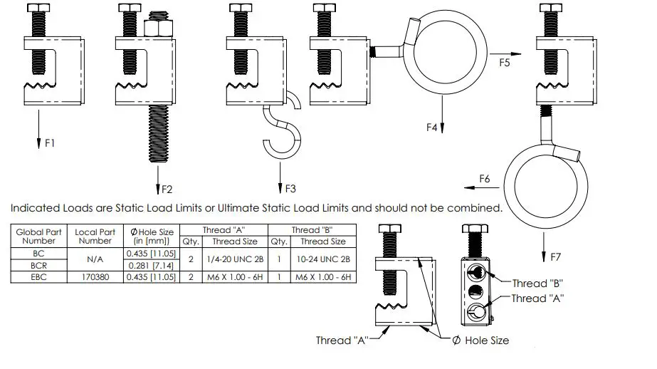
BC Beam Clamp
| Global Part Number | Local Part Number | Figure No. | Flange Thickness (in [mm]) | Static Load Rating (lb [N]) | Ult. Static Load Rating (lb [N]) | |||||
| F1 | F2 | F3 | F4 | F5 | F6 | F7 | ||||
| BC | N/A | 1 | 1/2″ [13] Max | 100 [445] | 100 [445] | 75 [334] | 25 [111] | 25 [111] | 25 [111] | 25 [111] |
| BCR | ||||||||||
| EBC | 170380 | |||||||||
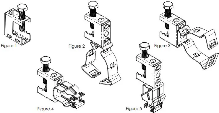
BC Beam Clamp with Bottom Mount Conduit Clip
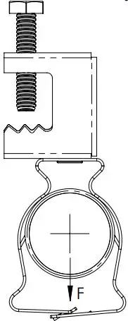
| Global Part Number | Local Part Number | Figure No. | Description | Static Load Rating (lb [N]) |
| BC6M |
N/A |
2 | 3/8″ [10]conduit to 1/2″ [13] maximum flange |
100 [445] |
| BC812M | 1/2″ [13] – 3/4″ [19] conduit to 1/2″ [13] maximum flange | |||
| BC16M | 3/4″ [19] – 1″ [25]conduit to 1/2″ [13] maximum flange | |||
| BC20M | 1-1/4″ [32]conduit to 1/2″ [13] maximum flange | |||
| BC24M | 1-1/2″ [38]conduit to 1/2″ [13] maximum flange | |||
| BC32M | 2″ [51]conduit to 1/2″ [13] maximum flange | |||
| EBC6M | 172580 | 3/8″ [10]conduit to 1/2″ [13] maximum flange | ||
| EBC812M | 160200 | 1/2″ [13] – 3/4″ [19] conduit to 1/2″ [13] maximum flange | ||
| EBC16M | 172590 | 3/4″ [19] – 1″ [25]conduit to 1/2″ [13] maximum flange | ||
| EBC20M | 172600 | 1-1/4″ [32]conduit to 1/2″ [13] maximum flange | ||
| EBC24M | 172610 | 1-1/2″ [38]conduit to 1/2″ [13] maximum flange | ||
| EBC32M | 172620 | 2″ [51]conduit to 1/2″ [13] maximum flange |
BC Beam Clamp with Side Mount Conduit Clip
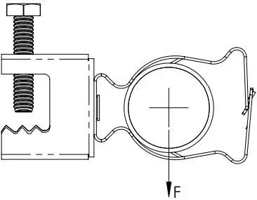
| Global Part Number | Local Part Number | Figure No. | Description | Static Load Rating (lb [N]) |
| BC812MSM |
N/A |
3 | 1/2″ [13] – 3/4″ [19] conduit to 1/2″ [13] maximum flange |
25 [111] |
| BC16MSM | 3/4″ [19] – 1″ [25]conduit to 1/2″ [13] maximum flange | |||
| BC20MSM | 1-1/4″ [32]conduit to 1/2″ [13] maximum flange | |||
| BC24MSM | 1-1/2″ [38]conduit to 1/2″ [13] maximum flange | |||
| BC32MSM | 2″ [51]conduit to 1/2″ [13] maximum flange | |||
| EBC6MSM | 172650 | 3/8″ [10]conduit to 1/2″ [13] maximum flange | ||
| EBC812MSM | 160180 | 1/2″ [13] – 3/4″ [19] conduit to 1/2″ [13] maximum flange | ||
| EBC16MSM | 172660 | 3/4″ [19] – 1″ [25]conduit to 1/2″ [13] maximum flange | ||
| EBC20MSM | 172670 | 1-1/4″ [32]conduit to 1/2″ [13] maximum flange | ||
| EBC24MSM | 172680 | 1-1/2″ [38]conduit to 1/2″ [13] maximum flange | ||
| EBC32MSM | 172690 | 2″ [51]conduit to 1/2″ [13] maximum flange |
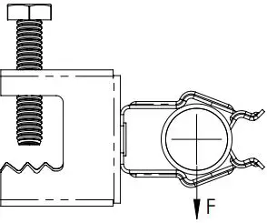
BC Beam Clamp with Side Mount Push Clip
BC Beam Clamp with Bottom Mount Push Clip
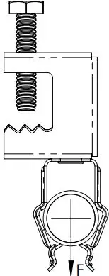
| Global Part Number | Local Part Number | Figure No. | Description | Ultimate Static Load Rating (lb [N]) |
| BC8P | N/A |
5 | 1/2″ [13] EMT conduit to 1/2″ [13] maximum flange |
25 [111] |
| BC12P | 3/4″ [19] EMT or 1/2″ [13] Rigid conduit to 1/2″ [13] max flange | |||
| BC16P | 1″ [25] EMT or 3/4″ [19] Rigid conduit to 1/2″ [13] max flange | |||
| EBC8P | 172700 | 1/2″ [13] EMT conduit to 1/2″ [13] maximum flange | ||
| EBC12P | 172710 | 3/4″ [19] EMT or 1/2″ [13] Rigid conduit to 1/2″ [13] max flange | ||
| EBC16P | 172720 | 1″ [25] EMT or 3/4″ [19] Rigid conduit to 1/2″ [13] max flange |
nVent, nVent CADDY, nVent ERICO Cadweld, nVent ERICO Critec, nVent ERICO, nVent ERIFLEX, and nVent LENTON are owned by nVent or its global affiliates. All other trademarks are the property of their respective owners. nVent reserves the right to change specifications without prior notice.
TECHNICAL SUPPORT: www.nVent.com


