Square D XUM4ApXBp XUM Photo Electric Sensors Instruction Manual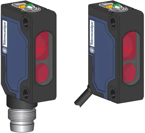
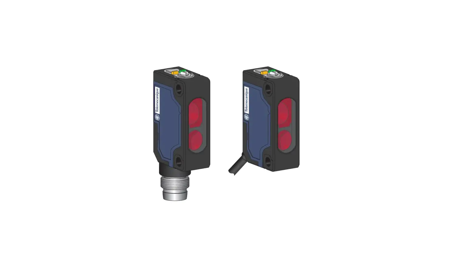
Photo-electric sensors – Miniature design

http://qr.tesensors.com/XU0007
 Scan the code to access this Instruction Sheet and all product information in different languages or you can visit our website at: www.tesensors.com
We welcome your comments about this document. You can reach us through the customer support page on your local website.
![]() DANGER
DANGER
HAZARD OF ELECTRIC SHOCK, EXPLOSION OR ARC FLASH
- Disconnect all power before servicing equipment.
- Do not connect this device to AC power.
- The power voltage must not exceed the rated range.
Failure to follow these instructions will result in death or serious injury.
![]() WARNING
WARNING
IMPROPER SETUP OR INSTALLATION
- This equipment must only be installed and serviced by qualified personnel.
- Read, understand, and follow the compliance below, before installing the XUM Photo-electric sensor.
- Do not tamper with or make alterations on the unit.
- Comply with the wiring and mounting instructions.
- Check the connections and fastening during maintenance operations.
- The proper functioning of the XUM photoelectric sensor and its operating line must be checked regularly and according to the application (for example number of operations, level of environmental pollution, etc.).
Failure to follow these instructions can result in death, serious injury, or equipment damage.
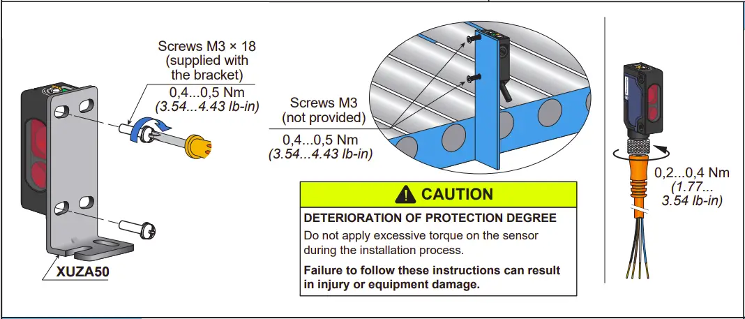
Mounting and tightening torques
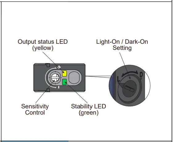
LEDs and settings
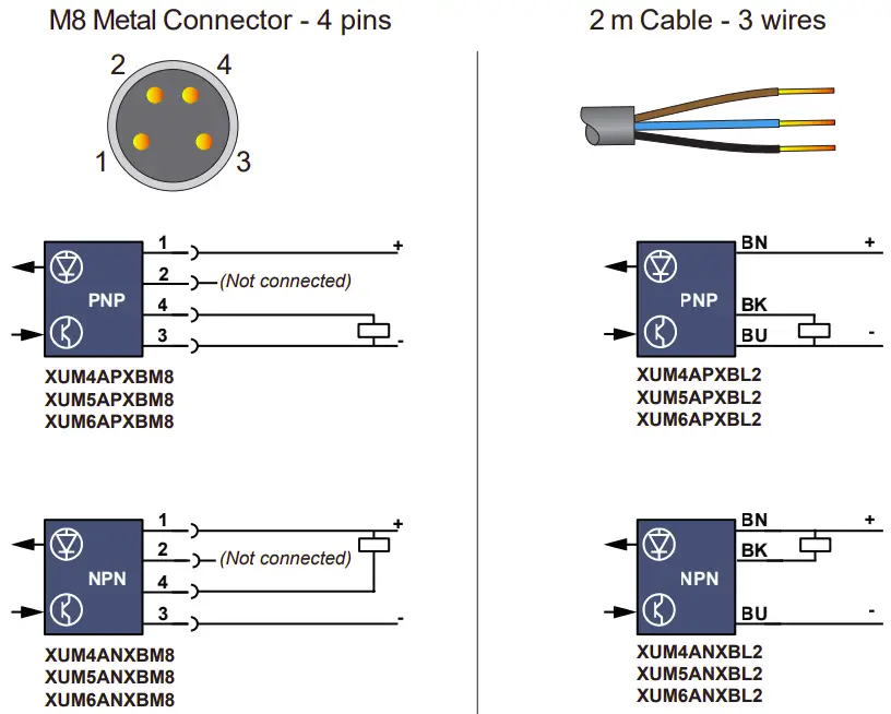
Wiring diagrams
Electrical equipment should be installed, operated and maintained only by qualified personnel.
No responsibility is assumed by Schneider Electric for any consequences arising out of the use of this material.
© 2023 Schneider Electric. “All Rights Reserved.”
Wiring precaution
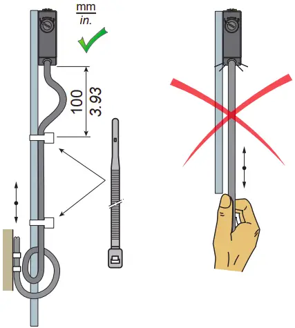
NOTICE
REDUCTION OF SERVICE LIFE
Do not pull on the sensor cable.
Failure to follow these instructions can result in equipment damage.
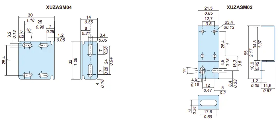
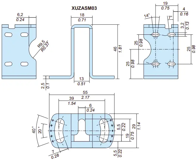
Dimensions
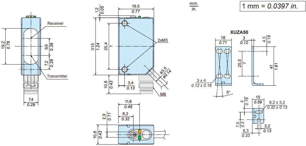
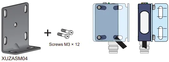
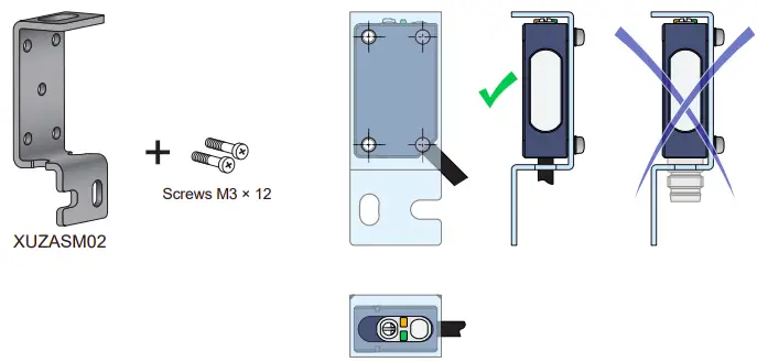
Accessories
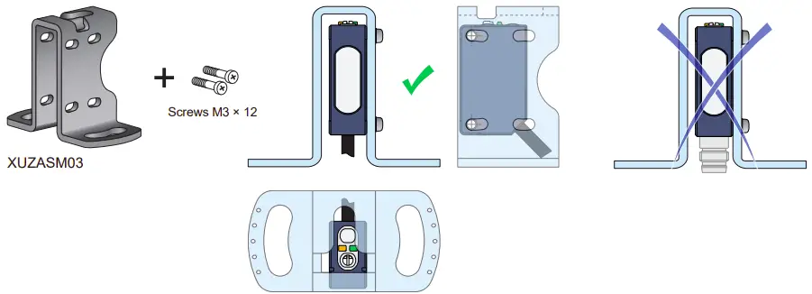
Mounting brackets (to order separately)

Pre-wired connectors (examples)
PVC cable for general use
PUR cable for severe industrial environments
| M8, 4 pins
Cable length | 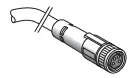 | 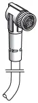 | M8 – M12, 4 pins
Jumper length | 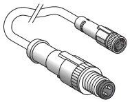 PUR | 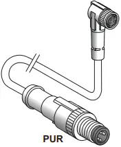 PUR | ||
| PVC | PUR | PVC | PUR | ||||
| 2 m / 6.56 ft. | XZCPV0941L2 | XZCP0941L2 | XZCPV1041L2 | XZCP1041L2 | 1 m / 3.28 ft. | XZCR1509041J1 | XZ CR1510041J1 |
| 5 m / 16.4 ft. | XZCPV0941L5 | XZCP0941L5 | XZCPV1041L5 | XZCP1041L5 | 2 m / 6.56 ft. | XZCR1509041J2 | XZCR1510041J2 |
| 10 m / 32.8 ft. | XZCPV0941L10 | XZCP0941L10 | XZCPV1041L10 | XZCP1041L10 | |||
Sensors position adjustment
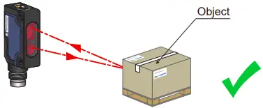
Anti-interference for side by side mounting
Anti-interference system to ensure good detection even disturbed by another sensor when mounted side by side
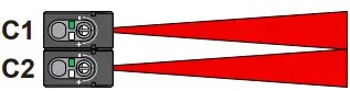
Anti-interference system allows a side by side installation and ensures a reliable detection.
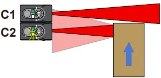
This Anti-interference system ensures an object detection in all conditions.
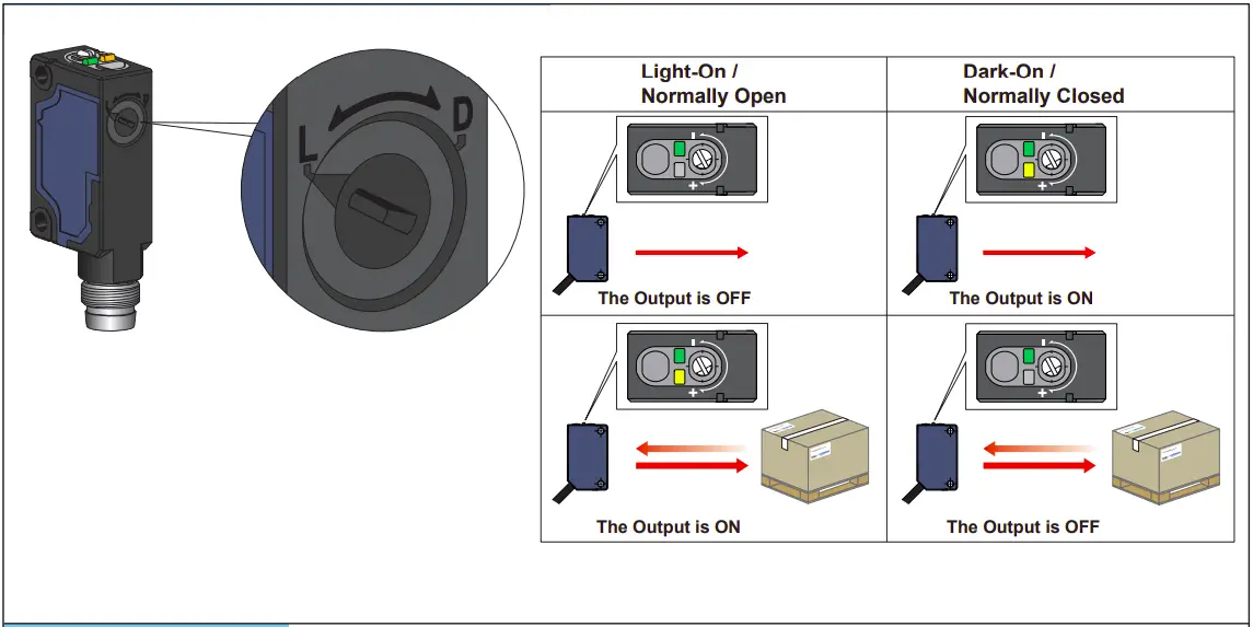
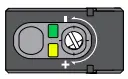
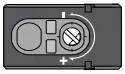
Output mode setting: Light-On or Dark-On (Light-On by default)
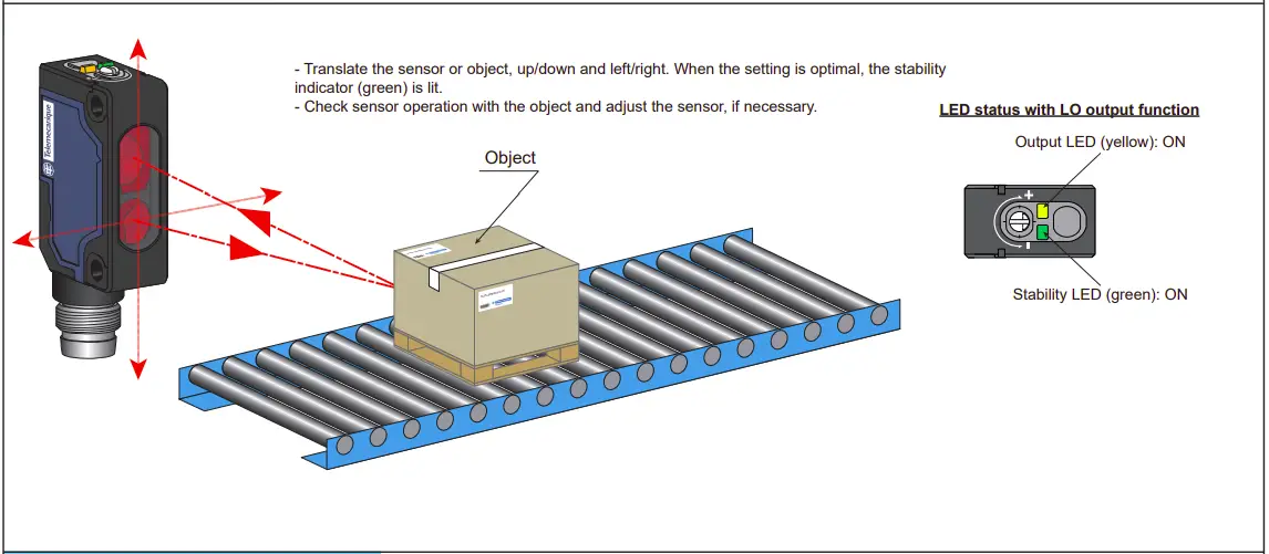
Sensor sensitivity adjustment
For an accurate detection, follow the set up below. (eg. Dark objects, with holes or with small size to reflect properly the light beam).
| Light-On | Dark-On | |
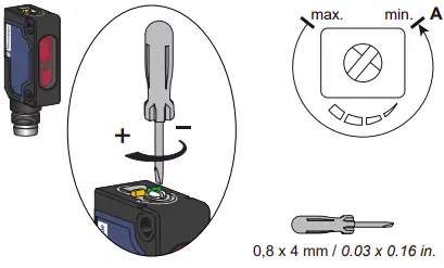 | 1-Connect the sensor to the power supply (see page 1 for the wire connection & page 7 for the power voltage). Before settings, start with the potentiometer at the minimum position (resulting to point A).
|
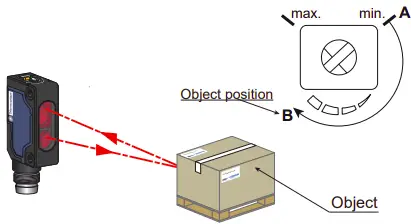 | 2-Put the object in front of the sensor. Turn clockwise the potentiometer until the output led (yellow) switches on (resulting to point B).
| 2-Put the object in front of the sensor. Turn clockwise the potentiometer until the output led (yellow) switches off (resulting to point B).
|
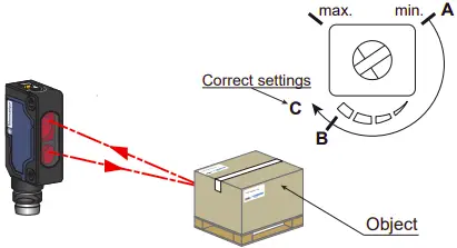 | 3-For a stable detection, turn the potentiometer clockwise until the stability led (green) switches on & the output led (yellow) remained on (resulting to point C).
| 3-For a stable detection, turn the potentiometer clockwise until the stability led (green) switches on & the output led (yellow) remained off (resulting to point C).
|
 | 4-The sensor is set and ready to detect
|


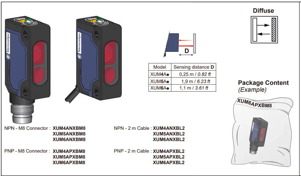
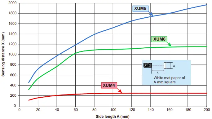
Detection curves
XUM4: Diffuse reflective (0,25 m) – Object size / Sensing distance
XUM5: Diffuse reflective (1,9 m) – Object size / Sensing distance
XUM6: Diffuse reflective (1,1 m) – Object size / Sensing distance
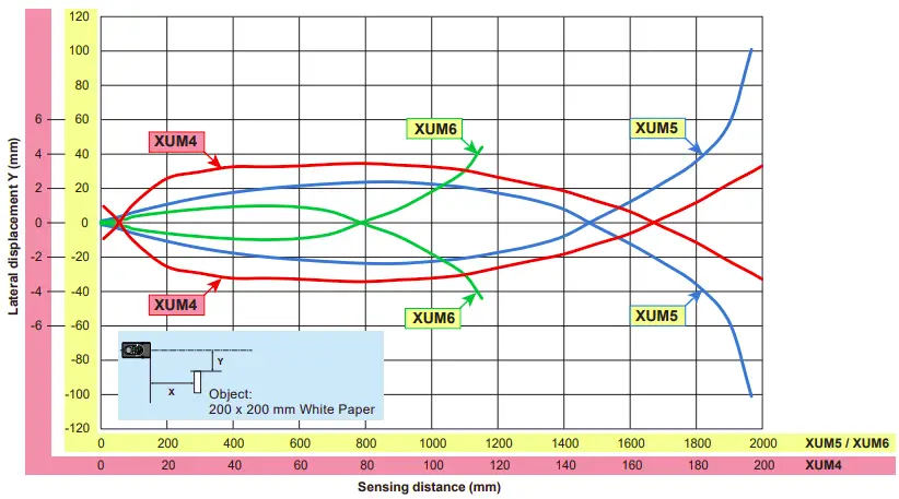
XUM4: Diffuse reflective (0,25 m) – Lateral displacement
XUM5: Diffuse reflective (1,9 m) – Lateral displacement
XUM6: Diffuse reflective (1,1 m) – Lateral displacement
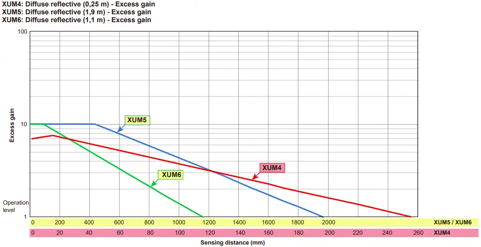
XUM4: Diffuse reflective (0,25 m) – Excess gain
XUM5: Diffuse reflective (1,9 m) – Excess gain
XUM6: Diffuse reflective (1,1 m) – Excess gain
Characteristics
| Certification | CE – UKCA – cULus |
| Sensing Range (using a white paper 200 x 200) Max. sensing distance (excess gain=1) | XUM5: 1,9 m – excess gain =1 1,5 m – excess gain=2 XUM6: 1,1 m – excess gain =1 0,8 m – excess gain=2 XUM4: 0,25 m – excess gain =1 0,17 m – excess gain=2 |
| Color of detection light beam | XUM6: Red – XUM5 / XUM4: Infrared |
| Blind zone | XUM4 / XUM5 / XUM6: 10 mm |
| Hysteresis | 2% < H < 20% (at most sensitivity, white paper) |
| Sensing distance setting | Potentiometer 1 turn (~ 240 degres) |
| Light-On/Dark-On selection | Switch (~ 120 degres) |
| Output type | PNP or NPN |
| ON Voltage drop | 2 V max. (30 Vdc 100 mA) / 1,2 V max. (30 Vdc 10mA) |
| Current consumption | < 20 mA max. |
| Switching capacity | 100 mA |
| Response time | 0,5 ms max |
| Recovery time | 0,5 ms max |
| Switching frequency | 1000 Hz |
| Electrostatic discharge immunity | 4 kV (Contact), 8 kV (Air) conforming to IEC 61000-4-2 |
| Electromagnetic field immunity | 10 V/m conforming to IEC 61000-4-3 |
| Fast transients immunity | Burst 5 kHz – 2kV conforming to IEC 61000-4-4 |
| Conducted disturbances immunity | 10 V conforming to IEC 61000-4-6 |
| Emissivity Radiated disturbances | Class A conforming to EN 55011 / CISPR 11 |
| Power Voltage | Rated operational voltage: 12…24 Vdc Ripple p-p 10% maximum Operating range: 10…30 Vdc (including ripple) |
| Product protection | Power supply : Reverse polarity protection Output: Short circuit protection Reverse polarity protection |
| Light Immunity | Operating atmosphere; Sunlight 40 kLx max. Incandescent light 10 kLx max |
| Ambient Temperature | Operating : – 30…+55 °C (-22…+131 °F), Storage : – 40…+70 °C (-40…+158 °F) |
| Ambient Humidity | Operating : 35…95% RH, Storage : 35…95% RH |
| Degree of protection | IP65, IP67 conforming to IEC 60529 |
| Vibration resistance | Frequency range: 10 Hz to 500 Hz Acceleration: 9 gn |
| Shock resistance | Peak acceleration: 100 gn Duration of the pulse: 11 ms |
| Material | Housing: PBT, Lens: PMMA, Operation cover: PC, Adjustment potentiometer: PBT |
![]() Manufacturer :
Manufacturer :
Schneider Electric Industries SAS
35 rue Joseph Monier
92500 Rueil Malmaison
France
 UK Representative :
Schneider Electric Limited
Stafford Park 5
Telford, TF3 3BL
United Kingdom


 Rectangular Photoelectric Sensor Instruction Manual")


