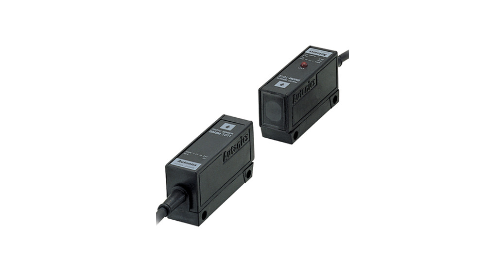
![]() BM-SENSORS Photo Electric Sensor
BM-SENSORS Photo Electric Sensor
User Guide
Conditioning electronics must often be added to an LVDT or Half Bridge sensor to interface with real-world environments.
Solartron Metrology‘s range of conditioning electronics offers users the ability to connect and configure LVDT and Half Bridge inductive sensors into an almost infinite number of combinations.
Outputs include voltage, current loops (4-20 mA) and TTL.
For optimum performance in terms of transducers and electronics please consider Solartron Metrology’s Orbit®
3 Digital Measurement System which outperforms the conventional analogue LVDT and Half Bridge sensors in all aspects.
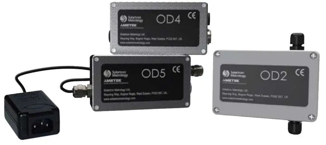
OD Series
The OD series of conditioning units is used to interface with Solartron’s sensors to provide different functions to suit different applications. The OD2 is a two-wire 4-20 mA signal conditioner. It is designed for signal transmission over long distances due to low noise susceptibility. The OD4 (OD5 is a mains-powered equivalent) is powered from a single 10 to 30 V DC supply. The outputs are fully adjustable for offset and gain.
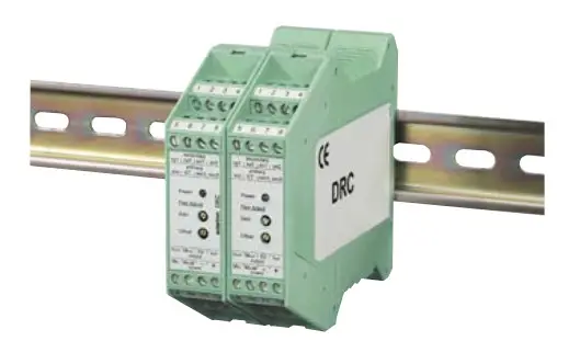
DRC
The DRC is a DIN rail-mounted version of the OD4 and provides all the features plus the convenience of a DIN rail mount.
BICM In-Line Module
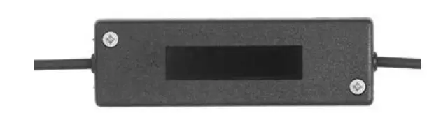
The BICM provides a simple low-cost line conditioning unit.
This is ideal when the transducer set-up is unlikely to require adjustment. For use in harsh environments, an IP67 version is available.
| Module | ATM TTL converter |
| Measurement | |
| Sensor Types | All Solartron Displacement Sensors |
| Accuracy(%FSO) | <0.25 |
| Resolution (x4 interpolation) | 0.1 |
| Repeatability | Sensor Dependent |
| Electrical | |
| Power | +5 ±0.25 VDC @ 100 mA |
| Output Signal | A & B,/ A and / B TTL square waves RS422 levels |
| Output frequency (kHz) | 50, 100, 125, 250 & 500 (factory selectable) |
| Bandwidth | 100 Hz |
| Environmental (electronics) | |
| Sealing | IP43 |
| Operating Temperature(°C) | 0 to +60 |
| Storage temperature(°C) | -20 to +70 |
Refer to product manual 502724 for details of operation – contact sales office
ATM TTL Converter
TTL RS 232 Differential Quadrature is one of the most commonly used methods of communication between Linear Displacement Sensors and Control or Data Acquisition Systems. Its simplicity of Interfacing with programmable systems also makes Solartron‘s ATM one of the most cost-effective.
Technical Specifications
| Module | OD2 | OD4 | OD5 | DRC | BICM | |
| Power requirements | ||||||
| Input Voltage VDC | 13-42 | 30-Oct | N/A | 30-Oct | ±15 | 24 (Note 5) |
| Input Voltage VAC | N/A | N/A | 90-264 | N/A | N/A N/A | |
| Input Current (mA) | <30 | 140-50 | 250-100 | 160-70 | ±12 24 | |
| Frequency (Hz) | 47-63 | |||||
| Sensor Excitation a | ||||||
| Primary Voltage (Vrms) | 0-9 | 3 | 1/2/21 | |||
| Primary Frequency (kHz) | 5 or 13 | 2.5 or 5 | 5, 10 or 13 | 5 | ||
| Signal Input. | ||||||
| Input Range | 30-530 mV (Note 1) | 55 to 5000 mV LVDT full range | up to 3.5 | |||
| Input Load (k0) | 2 | 2, 10, 100 | 2,100 | 100 | ||
| Options | Forward and reverse polarity, half-bridge | see (Note 2) | ||||
| Signal Output (Note 4) | ||||||
| Voltage Output VDC | Up to ±10 | |||||
| Current Output mA | 4-20 | Up to ±20 into 150 O load | ||||
| Output Ripple | <38 pA rms | <1 mV rms | <14 mV | |||
| Output Offset | Up to 100% on maximum gain (coarse and fine adjustment) | |||||
| Temperature Coefficient Gain (%FS0/°C) | <0.01 | <0.03 | ||||
| Temperature Coefficient Offset (%FSO/°C) | <0.01 | <0.02 | ||||
| Warm Up (minutes) | 15 Minutes | |||||
| Linearity (%FSO) | <0.02 | <0.1 | ||||
| Bandwidth (-3 dB) (Hz) | 25 | 500, 1 k | 250 | |||
| Environmental (Note 3) | ||||||
| Storage Temperature | -40 to +80 | -20 to +80 | ||||
| Operating Temperature | 0 to +60 | |||||
| IP Rating | 65 | 40 | None | 40/67 40 | ||
| Mechanical | ||||||
| Sensor Connections | Terminals | Din Connector | Terminals | Solder or factory fit for IP67 | ||
| Power Connections | Terminals | IEC320 C14 | ||||
| Weight | ||||||
| Material | ABS | Painted Aluminium Box | Plastic | Plastic or Stainless | Steel (IP67) | |
| Mounting | Holes | DIN rail | ||||
- Note 1: For transducers with sensitivity > 250 mV, an attenuator is required – contact sales
- Note 2: Transducer connected via external screw terminal. Users can therefore configure options
- Note 3: For higher environmental levels (and other custom options) contact the sales office
- Note 4: For custom options contact the Sales office
- Note 5: 24 V BICM, not available in IP67
Outputs
The correct selection of outputs is critical to accurate noise-free transmission. All analogue signals are more prone to interference than digital transmission methods such as TTL. The use of current as a transmission method can offer significant advantages over long cable runs.
With all external conditioning, it is possible to adjust both the offset voltage and the gain to give numerous outputs.
combinations and to increase sensitivity over a predefined measurement range.
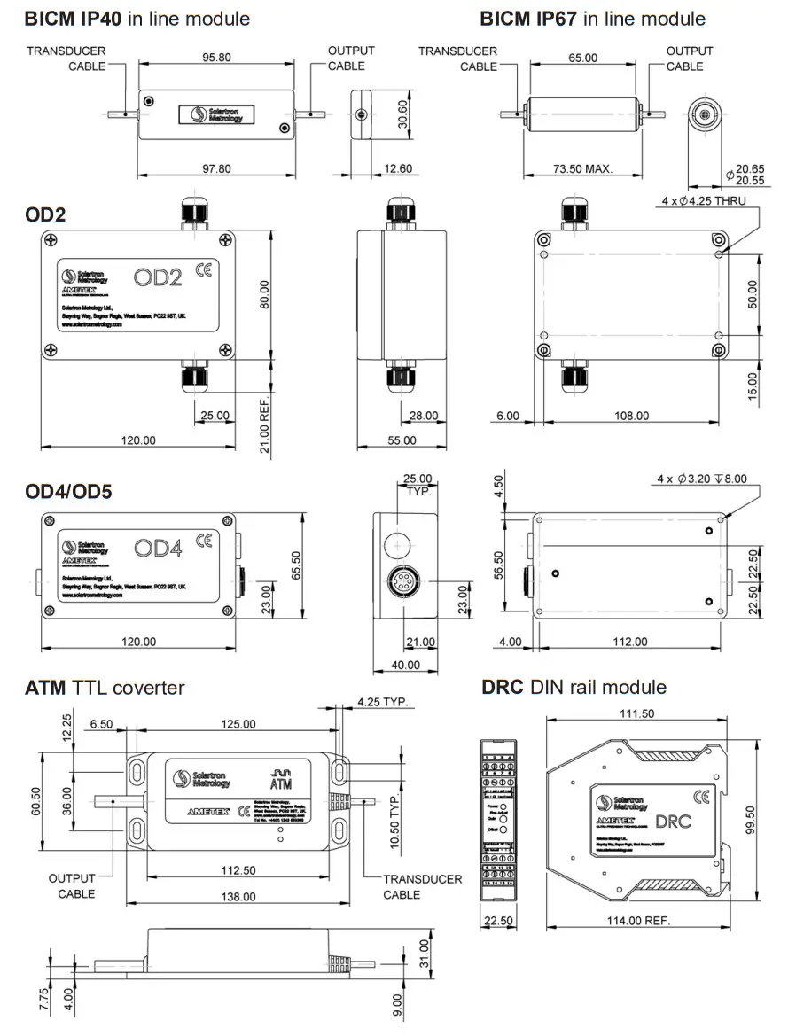
Signal conditioning modules
Dimensions (mm)
T: +49 69 1534 1776
E: [email protected]


 Rectangular Photoelectric Sensor Instruction Manual")


