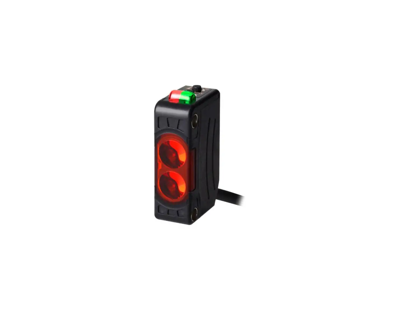
Autonics BJ Series (Cable type) Rectangular Photoelectric Sensor
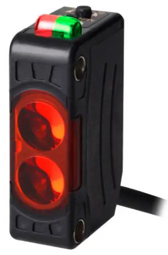
Rectangular Photoelectric Sensor BJ Series
Product Information
- The BJ Series rectangular photoelectric sensor is available in different sensing types including through-beam, polarized retroreflective, diffuse reflective, BGS reflective, and narrow beam reflective.
- The product has a sensing distance ranging from millimeters to meters.
- The BJ Series comes with different control output options including NPN open collector output and PNP open collector output.
- The product comes with a fail-safe device that must be installed when using the unit with machinery that may cause serious injury or substantial economic loss such as nuclear power control,medical equipment, ships, vehicles, railways, aircraft, combustion apparatus, safety equipment, crime/disaster prevention devices,etc.
- The BJ Series should not be used in places where flammable/explosive/corrosive gas, high humidity, direct sunlight,radiant heat, vibration, impact or salinity may be present.
Product Usage Instructions
- Always install the fail-safe device when using the sensor with machinery that may cause serious injury or economic loss.
- Avoid using the product in places where flammable/explosive/corrosive gas, high humidity, direct sunlight, radiant heat, vibration, impact or salinity may be present to prevent explosion or fire.
- Do not disassemble or modify the product to avoid fire.
- Do not connect, repair, or inspect the unit while connected to a power source as it may result in fire.
- Always check the connections before wiring to prevent fire.
- Use the sensor within its rated specifications to avoid fire or product damage.
- Clean the sensor with a dry cloth and avoid using water or organic solvent to clean it as it may result in fire.
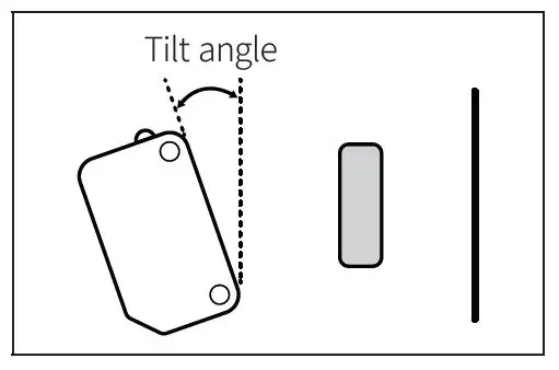
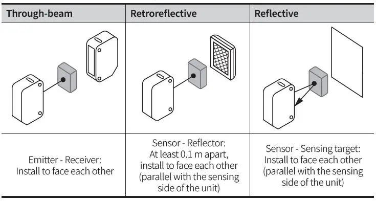
- When installing the sensor, follow the recommended tilt angle for through-beam, retroreflective and reflective sensing types.
- For sensor-reflector installations, ensure that they are at least 0.1m apart and parallel with the sensing side of the unit.
For BGS reflective types, recommend horizontal/back and forth movements of sensing target. - When selecting a specified model, follow the Autonics website as the actual product does not support all combinations.
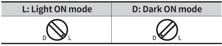
- Refer to the operation timing chart for Light ON mode and Dark ON mode.
Model BJ Series (Cable type)
Thank you for choosing our Autonics product.
Read and understand the instruction manual and manual thoroughly before using the product.
For your safety, read and follow the below safety considerations before using. For your safety, read and follow the considerations written in the instruction manual, other manuals and Autonics website.
Keep this instruction manual in a place where you can find easily.
The specifications, dimensions, etc. are subject to change without notice for product improvement. Some models may be discontinued without notice.
Follow Autonics website for the latest information.
Safety Considerations
- Observe all ‘Safety Considerations’ for safe and proper operation to avoid hazards.
 symbol indicates caution due to special circumstances in which hazards may occur.
Warning Failure to follow instructions may result in serious injury or death.
- Fail-safe device must be installed when using the unit with machinery that may cause serious injury or substantial economic loss. (e.g., nuclear power control, medical equipment, ships, vehicles, railways, aircraft, combustion apparatus, safety equipment, crime/disaster prevention devices, etc.) Failure to follow this instruction may result in personal injury, economic loss or fire.
- Do not use the unit in the place where flammable/explosive/corrosive gas, high humidity, direct sunlight, radiant heat, vibration, impact or salinity may be present.
Failure to follow this instruction may result in explosion or fire. - Do not disassemble or modify the unit.
Failure to follow this instruction may result in fire. - Do not connect, repair, or inspect the unit while connected to a power source.
Failure to follow this instruction may result in fire. - Check ‘Connections’ before wiring.
Failure to follow this instruction may result in fire.
Caution Failure to follow instructions may result in injury or product damage.
- Use the unit within the rated specifications.
Failure to follow this instruction may result in fire or product damage. - Use a dry cloth to clean the unit, and do not use water or organic solvent.
Failure to follow this instruction may result in fire.
Cautions during Use
- Follow instructions in ‘Cautions during Use’. Otherwise, It may cause unexpected accidents.
- When connecting an inductive load such as DC relay or solenoid valve to the output, remove surge by using diodes or varistors.
- Use the product after 0.5 sec of the power input.
When using a separate power supply for the sensor and load, supply power to the sensor first. - 12-24 VDC
 power supply should be insulated and limited voltage/current or Class 2, SELV power supply device.
 - Wire as short as possible and keep it away from high voltage lines or power lines to prevent surge and inductive noise.
- When using the switching mode power supply (SMPS), ground the F.G. terminal and connect a condenser between 0V and F.G. terminal to remove noise.
- When using a sensor with noise-generating equipment (e.g., switching regulator, inverter, and servo motor), ground F.G. terminal of the equipment.
- This unit may be used in the following environments.
- Indoors (in the environment condition rated in ‘Specifications’)
- Altitude max. 2,000 m
- Pollution degree 3
- Installation category II
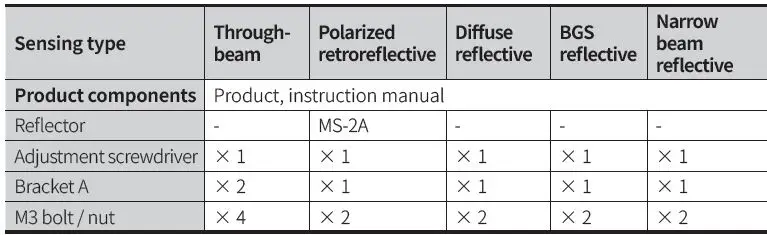
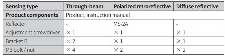
Product Components
Ordering Information
This is only for reference, the actual product does not support all combinations. For selecting the specified model, follow the Autonics website.

- Feature
No mark: General type
G: Transparent glass sensing type (Diffuse reflective type )
N: Micro spot type
(Narrow beam reflective type) - Sensing distance
Number: Sensing distance (unit: mm) Number+M: Sensing distance (unit: m) - Sensing type
T: Through-beam
P: Polarized retroreflective D: Diffuse reflective
B: BGS reflective
N: Narrow beam reflective - Control output
No mark: NPN open collector output P: PNP open collector output
Sold Separately
- Reflector: MS Series
- Retroreflective tape: MST Series
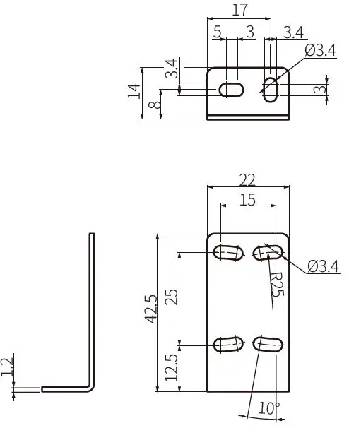
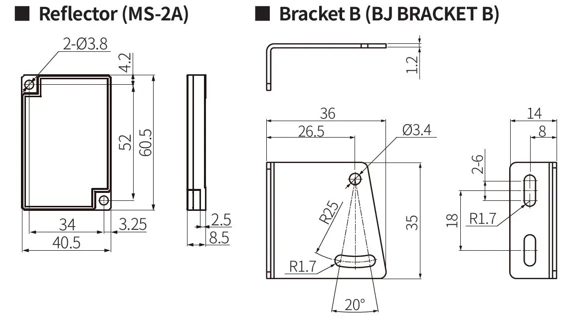
- Bracket B: BJ BRACKET B
Cautions during Installation
- Be sure to install this product by following the usage environment, location, and specified ratings. Consider the listed conditions below.
- Installation environment and background (reflected light)
- Sensing distance and sensing target
- Direction of target’s movement
- Feature data
- When installing multiple sensors closely, it may result in malfunction due to mutual interference.
- BGS reflective : If the sensing target has a glossy surface or high reflection, tilt the sensor with an angle from 5 to 10 degrees and install it. Get rid of the effect of background object on the sensing performance.
- Narrow beam reflective: Mount the sensor tilted at an angle from 0 to 15 degrees for stable copper wire detection.

- For installation, tighten the screw with a torque of 0.5 N m. Mount the brackets correctly to prevent the twisting of the sensor’s optical axis.
- Do not impact with a hard object or bend the cable excessively. That could decrease the product’s water resistance.
- Use this product after the test. Check whether the indicator works appropriately for the positions of the detectable object.
| Through-beam | Retroreflective | Reflective |
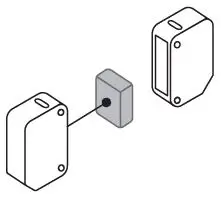 | 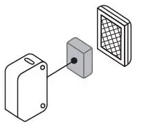 | 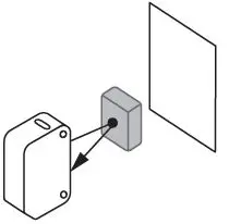 |
| Sensor-Sensing target: | ||
| Emitter – Receiver: Install to face each other | Sensor – Reflector: At least 0.1 m apart, install to face each other (parallel with the sensing side of the unit) | Install to face each other (parallel with the sensing side of the unit) BGS reflective: Recommend horizontal / back and force movements |
| of sensing target |
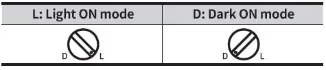
Setting Operation Mode
- Be sure to set the mode before power-on.
- Use the offered adjustment screwdriver. Do NOT turn with excessive force to prevent product damage.
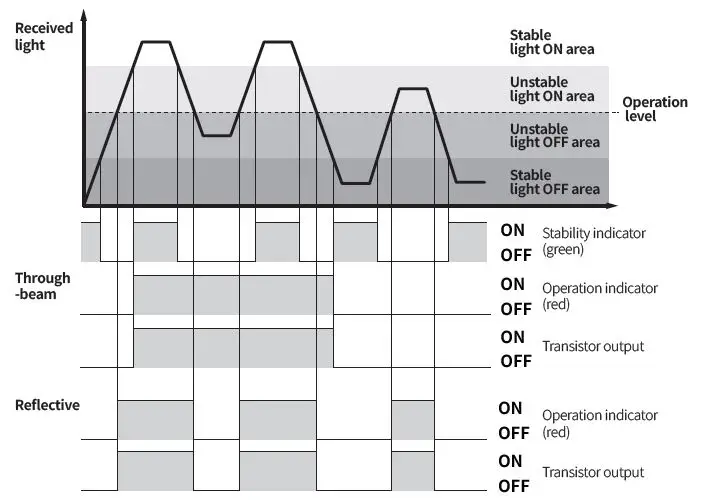
Operation Timing Chart
Light ON mode
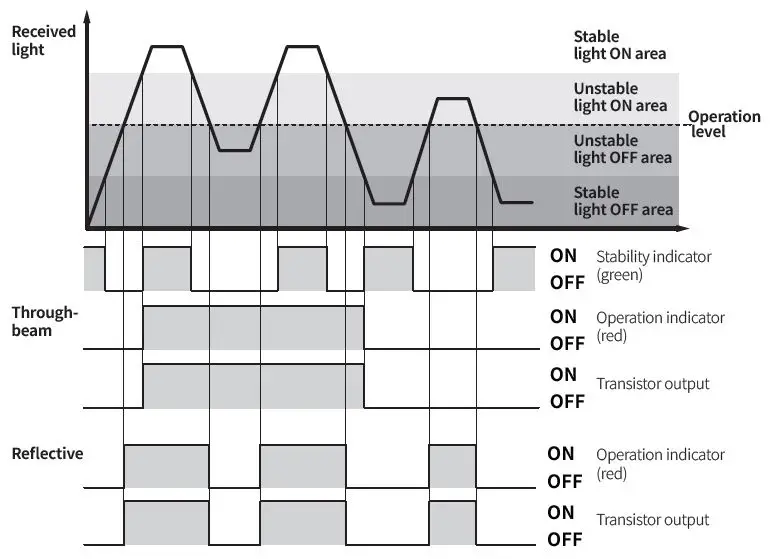
- In Dark ON mode, the waveforms are reversed.
- Operation indicator and transistor output differ from the sensing method.
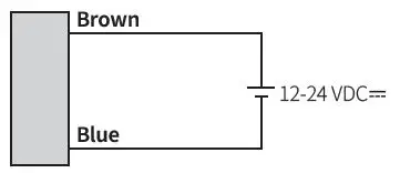
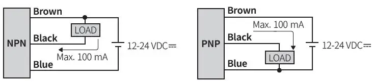
Connections
Emitter
Receiver, Polarized retroreflective/Diffuse/BGS/ Narrow beam reflective type
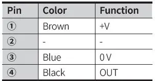
Circuit
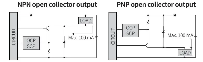
- OCP (over current protection), SCP (short circuit protection)
- If short-circuit the control output terminal or supply current over the rated specification, normal control signal is not output due to the protection circuit.
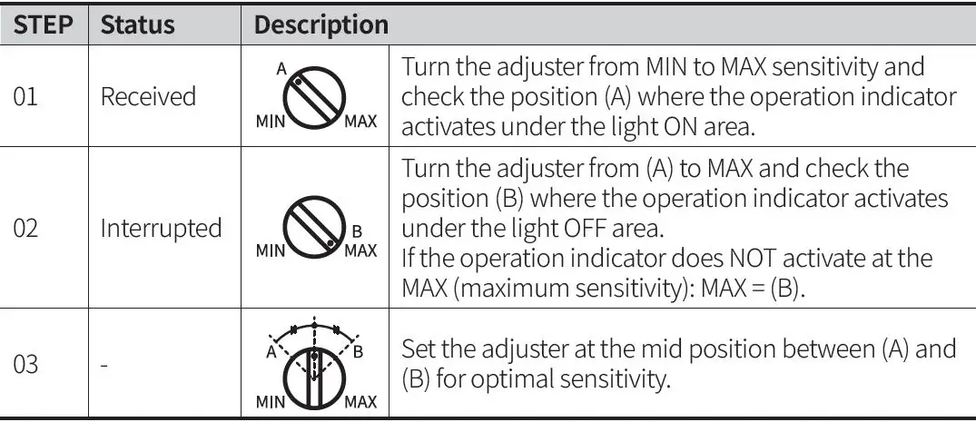
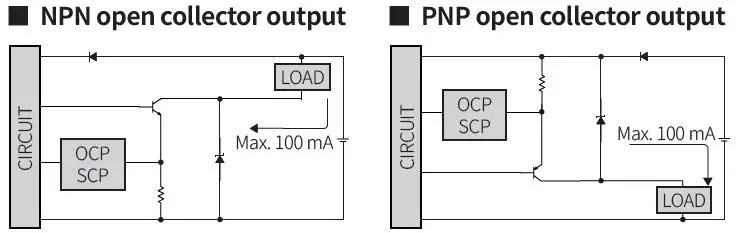
Sensitivity Adjustment
- Set the adjuster for stable Light ON area, minimizing the effect of the installation environment.
- Use the offered adjustment screwdriver. Do NOT turn with excessive force to prevent product damage.
- The steps below are based on Light ON mode.
Dimensions
- Unit: mm, For the detailed drawings, follow the Autonics website.
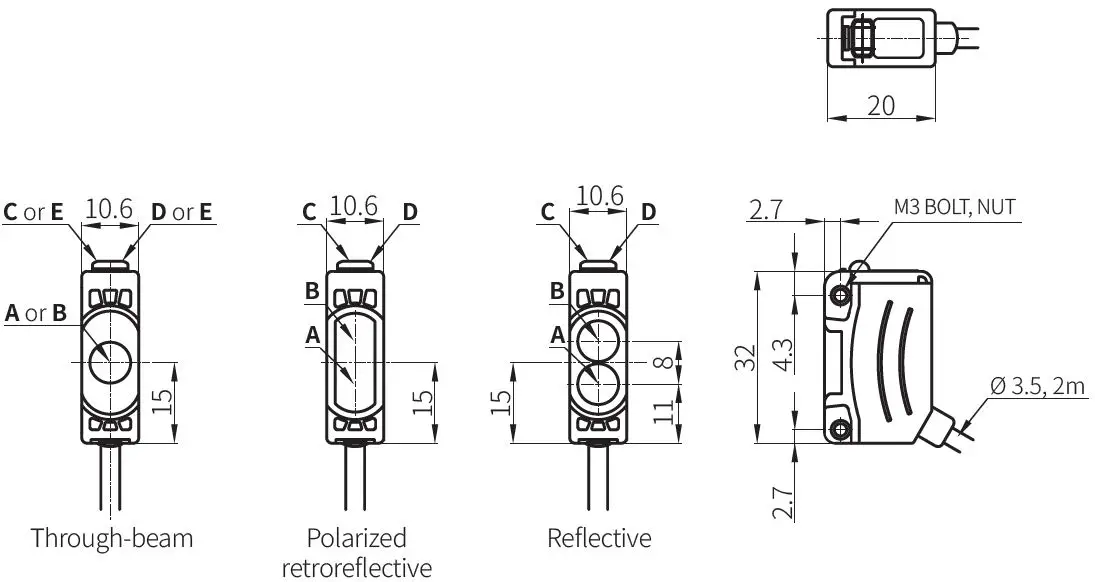
| A | Optical axis of emitter | D | Stability indicator (green) |
| B | Optical axis of receiver | E | Power indicator of emitter (green) |
| C | Operation indicator (red) |
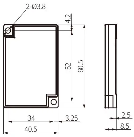
Reflector (MS-2A)
Bracket A
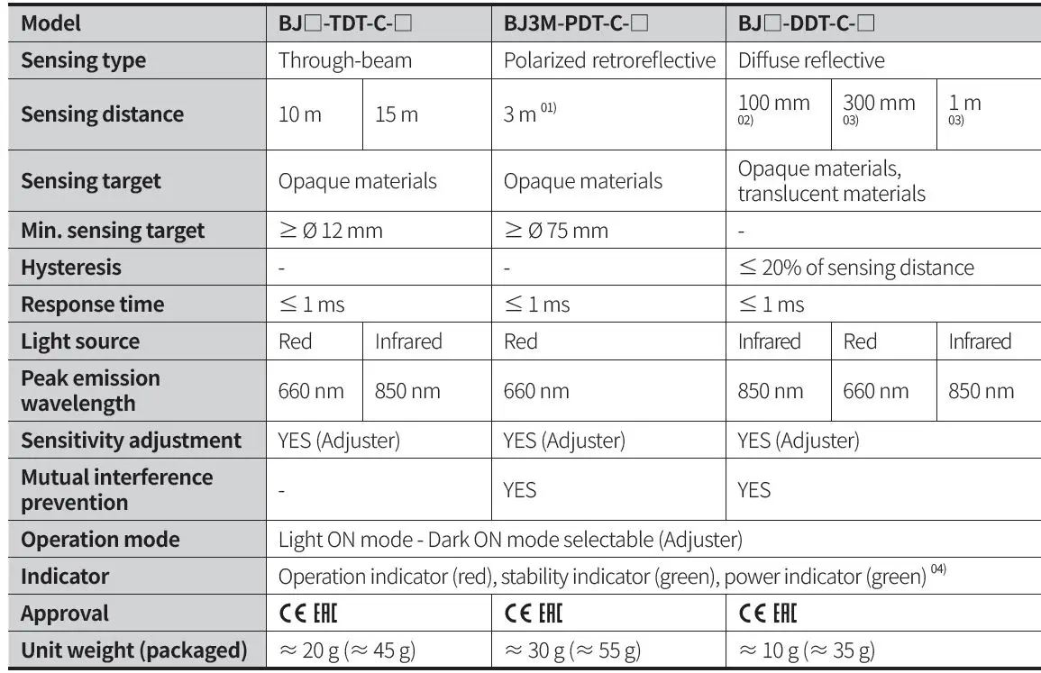
Specifications
| Model | BJ□-TDT-□ | BJ3M-PDT-□ | BJ□-BDT-□ | BJN□-NDT-□ | ||||
| Sensing type | Through-beam | Polarized retroreflective | BGS reflective | Narrow beam reflective | ||||
| Sensing distance | 7 m | 10 m | 15 m | 3 m 01) | 10 to 30 mm 02) | 10 to 50 mm 02) | 30 to 70 mm 03) | 70 to 130 mm 03) |
| Sensing target | Opaque materials | Opaque materials | Opaque materials, translucent materials | Opaque materials, translucent materials | ||||
| Min. sensing target | ≥ Ø 8 mm | ≥ Ø 12 mm | ≥ Ø 75 mm | – | ≥ Ø 0.2 mm (copper wire) | |||
| Hysteresis | – | – | ≤ 10% of sensing distance | ≤ 25% of sensing distance | ≤ 20% of sensing distance | |||
| Black/white difference | – | – | ≤ 10% of sensing distance | – | ||||
| Response time | ≤ 1 ms | ≤ 1 ms | ≤ 1.5 ms | ≤ 1 ms | ||||
| Light source | Red | Red | Infrared | Red | Red | Red | ||
| Peak emission wavelength | 650 nm | 660 nm | 850 nm | 660 nm | 660 nm | 650 nm | ||
| Min. spot size | – | – | ≈ Ø 5.0 mm | ≈ Ø 4.5 mm | ≈ Ø 2.0 mm | ≈ Ø 2.5 mm | ||
| Sensitivity adjustment | YES (Adjuster) | YES (Adjuster) | YES (Adjuster) 04) | YES (Adjuster) | ||||
| Mutual interference prevention | – | YES | – | YES | ||||
| Operation mode | Light ON mode – Dark ON mode selectable (Adjuster) | |||||||
| Indicator | Operation indicator (red), stability indicator (green), power indicator (green) 05) | |||||||
| Approval | ||||||||
| Unit weight (packaged) | ≈ 90 g (≈ 115 g) | ≈ 60 g (≈ 85 g) | ≈ 50 g | ≈ 45 g | ||||
- Reflector (MS-2A)
- Non-glossy white paper 50 × 50 mm
- Non-glossy white paper 100 × 100 mm
- -10% of max. sensing distance, Non-glossy white paper
- Only for the emitter
| Model | BJ□-DDT-□ | BJG30 -DDT | ||
| Sensing type | Diffuse reflective | Diffuse reflective | ||
| Sensing distance | 100 mm 01) | 300 mm 01) | 1 m 02) | 15 mm 03) or 30 mm 01) |
| Sensing target | Opaque materials, translucent materials | Transparent glass or opaque materials, translucent materials | ||
| Hysteresis | ≤ 20% of sensing distance | ≤ 20% of sensing distance | ||
| Response time | ≤ 1 ms | ≤ 1 ms | ||
| Light source | Infrared | Red | Infrared | Infrared |
| Peak emission wavelength | 850 nm | 660 nm | 850 nm | 850 nm |
| Sensitivity adjustment | YES (Adjuster) | – | ||
| Mutual interference prevention | YES | YES | ||
| Operation mode | Light ON mode – Dark ON mode selectable (Adjuster) | Light ON | ||
| Indicator | Operation indicator (red), stability indicator (green) | Operation indicator (red), stability indicator (green) | ||
| Approval | ||||
| Unit weight (packaged) | ≈ 45 g (≈ 70 g) | ≈ 45 g | ||
- Non-glossy white paper 100 × 100 mm
- Non-glossy white paper 300 × 300 mm
- Transparent Glass 50 × 50 mm, t = 3.0 mm
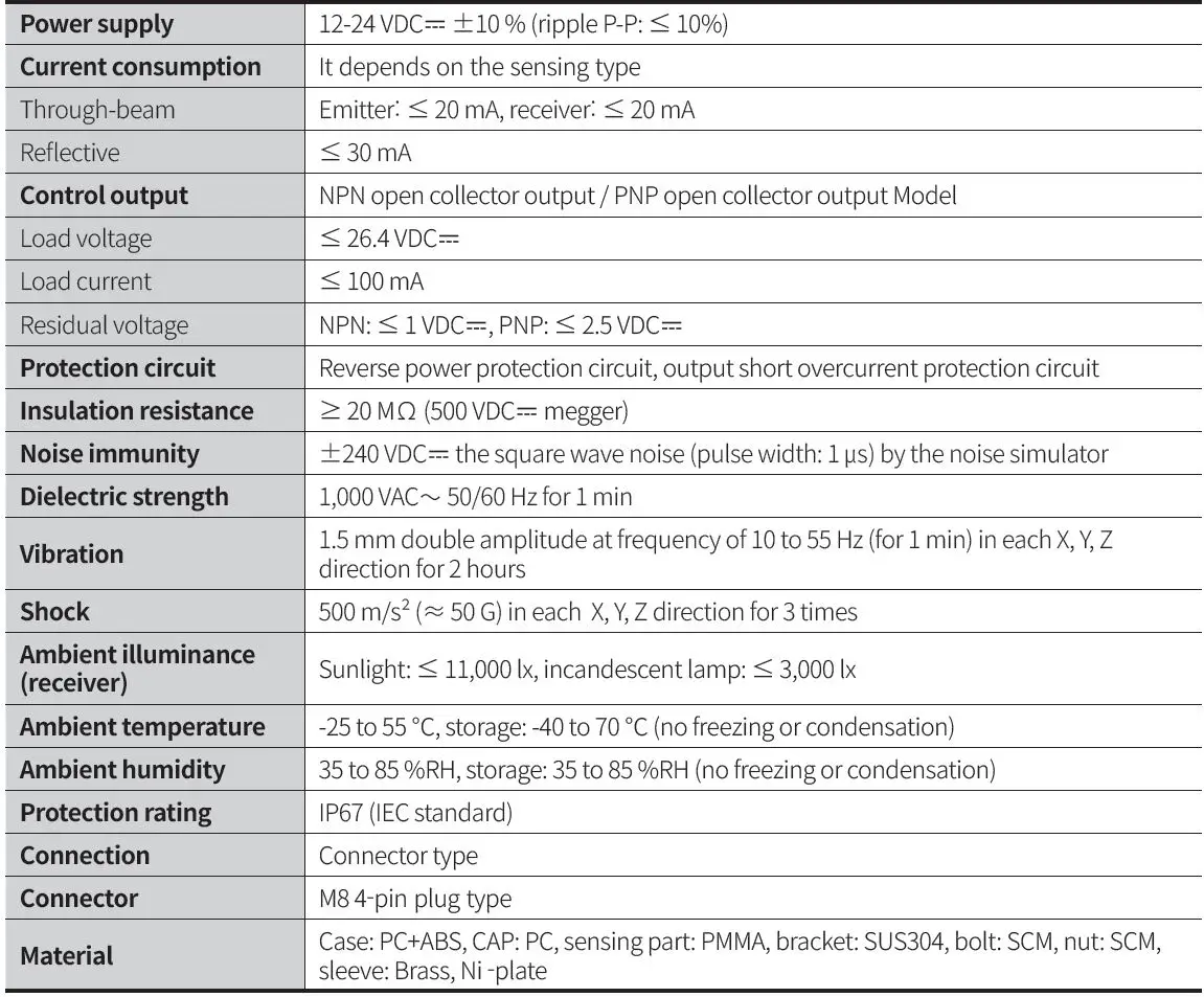
| Power supply | 12-24 VDCᜡ ±10 % (ripple P-P: ≤ 10%) |
| Current consumption | It depends on the sensing type |
| Through-beam | Emitter: ≤ 20 mA, receiver: ≤ 20 mA |
| Reflective | ≤ 30 mA |
| Control output | NPN open collector output / PNP open collector output model |
| Load voltage | ≤ 26.4 VDC |
| Load current | ≤ 100 mA |
| Residual voltage | NPN : ≤ 1 VDC |
| Protection circuit | Reverse power protection circuit, output short overcurrent protection circuit |
| Insulation resistance | ≥ 20 MΩ (500 VDC |
| Noise immunity | ±240 VDC |
| Dielectric strength | 1,000 VAC |
| Vibration | 1.5 mm double amplitude at frequency of 10 to 55 Hz (for 1 min) in each X, Y, Z direction for 2 hours |
| Shock | 500 m/s² (≈ 50 G) in each X, Y, Z direction for 3 times |
| Ambient illuminance (receiver) | Sunlight: ≤ 11,000 lx, incandescent lamp: ≤ 3,000 lx |
| Ambient temperature | -25 to 55 ℃, storage: -40 to 70 ℃ (no freezing or condensation) |
| Ambient humidity | 35 to 85 %RH, storage: 35 to 85 %RH (no freezing or condensation) |
| Protection rating | IP65 (IEC standard) |
| Connection | Cable type |
| Cable spec. | Ø 3.5 mm, 3-wire (emitter: 2-wire), 2 m |
| Wire spec. | AWG24 (0.08 mm, 40-core), insulator outer diameter: Ø 1 mm |
| Material | Case: PC+ABS, CAP: PC, sensing part: PMMA, bracket: SUS304, bolt: SCM, nut: SCM, sleeve: Brass, Ni-plate |
Model BJ Series (Connector type)
Thank you for choosing our Autonics product.
Read and understand the instruction manual and manual thoroughly before using the product.
For your safety, read and follow the below safety considerations before using. For your safety, read and follow the considerations written in the instruction manual, other manuals and Autonics website.
Keep this instruction manual in a place where you can find easily.
The specifications, dimensions, etc. are subject to change without notice for product improvement. Some models may be discontinued without notice.
Follow Autonics website for the latest information.
Safety Considerations
- Observe all ‘Safety Considerations’ for safe and proper operation to avoid hazards.
- symbol indicates caution due to special circumstances in which hazards may occur.
Warning Failure to follow instructions may result in serious injury or death.
- Fail-safe device must be installed when using the unit with machinery that may cause serious injury or substantial economic loss. (e.g., nuclear power control, medical equipment, ships, vehicles, railways, aircraft, combustion apparatus, safety equipment, crime/disaster prevention devices, etc.) Failure to follow this instruction may result in personal injury, economic loss or fire.
- Do not use the unit in the place where flammable/explosive/corrosive gas, high humidity, direct sunlight, radiant heat, vibration, impact or salinity may be present.
Failure to follow this instruction may result in explosion or fire. - Do not disassemble or modify the unit.
Failure to follow this instruction may result in fire. - Do not connect, repair, or inspect the unit while connected to a power source.
Failure to follow this instruction may result in fire. - Check ‘Connections’ before wiring.
Failure to follow this instruction may result in fire.
Caution Failure to follow instructions may result in injury or product damage.
- Use the unit within the rated specifications.
Failure to follow this instruction may result in fire or product damage. - Use a dry cloth to clean the unit, and do not use water or organic solvent.
Failure to follow this instruction may result in fire.
Cautions during Use
- Follow instructions in ‘Cautions during Use’. Otherwise, It may cause unexpected accidents.
- When connecting an inductive load such as a DC relay or solenoid valve to the output, remove the surge by using diodes or varistors.
- Use the product after 0.5 sec of the power input.
When using a separate power supply for the sensor and load, supply power to the sensor first. - 12-24 VDC power supply should be insulated and limited voltage/current or Class 2, SELV power supply device.
- Wire as short as possible and keep it away from high voltage lines or power lines to prevent surge and inductive noise.
- When using the switching mode power supply (SMPS), ground the F.G. terminal and connect a condenser between 0V and the F.G. terminal to remove noise.
When using a sensor with noise-generating equipment (e.g., switching regulator, inverter, and servo motor), ground the F.G. terminal of the equipment. - This unit may be used in the following environments.
- Indoors (in the environment condition rated in ‘Specifications’)
- Altitude max. 2,000 m
- Pollution degree 3
- Installation category II
Product Components
Ordering Information
This is only for reference, the actual product does not support all combinations.
For selecting the specified model, follow the Autonics website.

- Sensing distance
Number: Sensing distance (unit: mm)
Number+M: Sensing distance (unit: m) - Sensing type
T: Through-beam
P: Polarized retroreflective
D: Diffuse reflective - Control output
No mark: NPN open collector output
P: PNP open collector output
Sold Separately
- Reflector: MS Series
- Retroreflective tape: MST Series
Cautions during Installation
- Be sure to install this product by following the usage environment, location, and specified ratings. Consider the listed conditions below.
- Installation environment and background (reflected light)
- Sensing distance and sensing target
- Direction of target’s movement
- Feature data
- When installing multiple sensors closely, it may result in malfunction due to mutual interference.
- For installation, tighten the screw with a torque of 0.5 N m. Mount the brackets correctly to prevent the twisting of the sensor’s optical axis.
- Do not impact with a hard object or bend the cable excessively. That could decrease the product’s water resistance.
- Use this product after the test. Check whether the indicator works appropriately for the positions of the detectable object.
Setting Operation Mode
- Be sure to set the mode before power-on.
- Use the offered adjustment screwdriver. Do NOT turn with excessive force to prevent product damage.
Operation Timing Chart
Light ON mode
- In Dark ON mode, the waveforms are reversed.
- Operation indicator and transistor output differ from the sensing method.
Connections
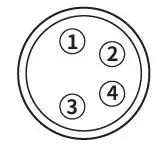
- Connector pin ④ is N.C (not connected) terminal for the emitter.
- Refer to ‘Circuit’ for the load connection.
Circuit
- OCP (over current protection), SCP (short circuit protection)
- If short-circuit the control output terminal or supply current over the rated specification, normal control signal is not output due to the protection circuit.
Dimensions
- Unit: mm, For the detailed drawings, follow the Autonics website.
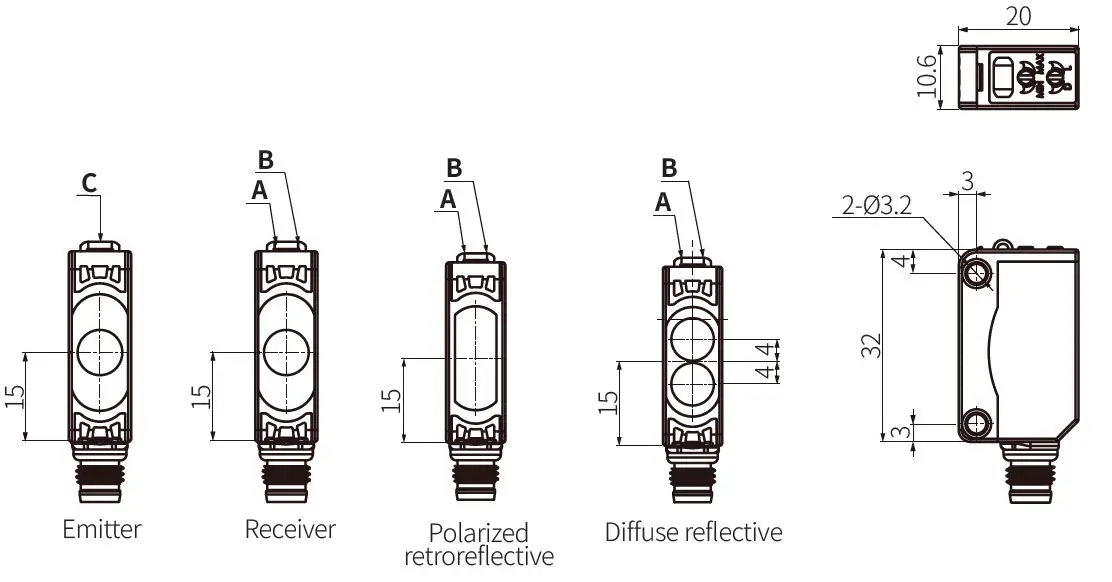
- A Operation indicator (red)
- B Stability indicator (green)
- C Power indicator (green)
Specifications
- Reflector (MS-2A)
- Non-glossy white paper 100 × 100 mm
- Non-glossy white paper 300 × 300 mm
- Only for the emitter
18, Bansong-ro 513Beon-gil, Haeundae-gu, Busan, Republic of Korea, 48002
www.autonics.com | +82-51-519-3232 | [email protected]


