AETEK I36-200 Gigabit High Power PoE Injector Series
Product Information
The Gigabit High Power PoE Injector Series is a collection of PoE injectors that provide power over Ethernet to various devices. The series includes the following models:
| Model | Description |
|---|---|
| I36-200 | Indoor 60W PoH PoE output |
| I36-210 | Indoor 60W IEEE 802.3 bt PoE output |
| I36-210-V2 | Indoor 60W IEEE 802.3 bt PoE output |
| I39-200 | Indoor 95W PoH PoE output |
| I39-210 | Indoor 90W IEEE 802.3 bt PoE output |
| I39-210-V2 | Indoor 90W IEEE 802.3 bt PoE output |
| I46-200 | Outdoor 60W PoH PoE output |
| I46-210 | Outdoor 60W IEEE 802.3 bt PoE output |
| I49-200 | Outdoor 95W PoH PoE output |
| I49-210-V2 | Outdoor 90W IEEE 802.3 bt PoE output |
| I49-201 | Outdoor 95W PoH PoE output |
| I49-211 | Outdoor 90W IEEE 802.3 bt PoE output |
| I69-200 | Industrial Gigabit 95W PoH PoE output |
| I69-210 | Industrial Gigabit 90W bt PoE output |
| I69-210-V2 | Industrial Gigabit 90W bt PoE output |
| I69-206 | Industrial Gigabit 95W PoH PoE output |
| I69-216 | Industrial Gigabit 90W bt PoE output |
| I69-216-V2 | Industrial Gigabit 90W bt PoE output |
The package contents include:
- 1x PoE injector
- 1x Quick Installation Guide
- 1x AC power cord (Indoor type only)
Product Usage Instructions
To install and use the Gigabit High Power PoE Injector, follow these steps:
- Connect the power cable to the injector. The Power LED (Yellow) should be lit.
- Connect the Data IN port to a LAN switch using an Ethernet cable.
- Connect the Power+Data OUT port to a powered device, such as an IP camera, using another Ethernet cable. Make sure the PoE LED is lit.
- Check if the powered device (IP camera) is working properly. Note that it may take up to 1 or 2 minutes for an IP camera to power up.
The LED definitions for the injector are as follows:
- Power LED: Green ON indicates power is good, OFF indicates power failure.
- PoE LED: Amber ON indicates PD detected.
The usage instructions vary depending on the model and application:
| Model | Description |
| I36-200 | Indoor 60W PoH PoE output |
| I36-210 | Indoor 60W IEEE 802.3 bt PoE output |
| I36-210-V2 | Indoor 60W IEEE 802.3 bt PoE output |
| I39-200 | Indoor 95W PoH PoE output |
| I39-210 | Indoor 90W IEEE 802.3 bt PoE output |
| I39-210-V2 | Indoor 90W IEEE 802.3 bt PoE output |
| I46-200 | Outdoor 60W PoH PoE output |
| I46-210 | Outdoor 60W IEEE 802.3 bt PoE output |
| I49-200 | Outdoor 95W PoH PoE output |
| Model | Description |
| I49-210-V2 | Outdoor 90W IEEE 802.3 bt PoE output |
| I49-201 | Outdoor 95W PoH PoE output |
| I49-211 | Outdoor 90W IEEE 802.3 bt PoE output |
| I69-200 | Industrial Gigabit 95W PoH PoE output |
| I69-210 | Industrial Gigabit 90W bt PoE output |
| I69-210-V2 | Industrial Gigabit 90W bt PoE output |
| I69-206 | Industrial Gigabit 95W PoH PoE output |
| I69-216 | Industrial Gigabit 90W bt PoE output |
| I69-216-V2 | Industrial Gigabit 90W bt PoE output |
PACKAGE CONTENTS
| Power | Green ON: power good; OFF: power failed. |
| PoE | Amber ON: PD datected |
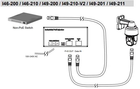
CONNECTION
Installation Steps
- Connect the power cable to the injector. The Power LED (Yellow) should be lit.
- Connect the Data IN port to a LAN switch using an Ethernet cable.
- Connect the Power+Data OUT port to a powered device, i.e., IP camera, using another Ethernet cable. Make sure the PoE LED is lit.
- Check if the powered device (IP camera) is working properly. An IP camera may take up to 1 or 2 minutes to power up.
LED definitions
| Power | Green ON: power good; OFF: power failed. |
| PoE | Amber ON: PD datected |
Application
I36-200 / I36-210 / I36-210-V2 / I39-200 / I39-210 / I39-210-V2
I69-200 / I69-210 / I69-210-V2 / I69-206 / I69-216 / I69-216-V2
Input Power :
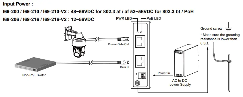
Application
AC Power Cable Spec.
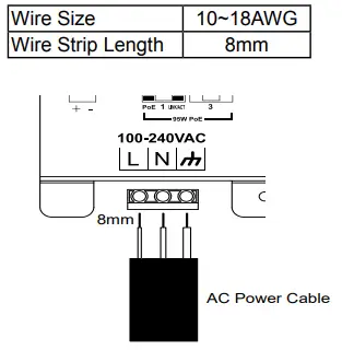
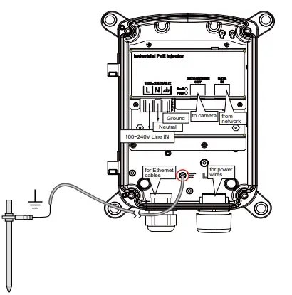
Route your power wires through a 3/4″ conduit into the power box. The wiring scheme is shown below. The power supply converts 100~240V power to the 95W PoE output to IP cameras.
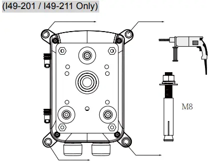
The power box can be mounted with the AT-100,AT-101 pole-mount, AT-200 corner-mount bracket, or directly secured to a wall. (I49-201 / I49-211 Only)
Use the included M8 hex socket screws to secure the power box to a pole-mount or corner mount bracket.
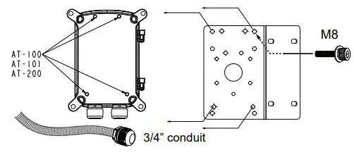
The mounting hole definition is illustrated below. The same mounting hole pattern apply to all pole-mount and corner-mount brackets.
If the power box is directly mounted to wall, drill holes in a diameter of 9.5mm or 3/8″, and 4cm deep.
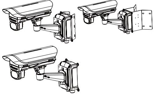
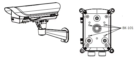
Use the following mounting positions for the camera housings (via BK-101 brackets). (I49-201 / I49-211 Only)
AETEK INC.
6F, No.192-1, Lien-Cheng Rd., Chung-Ho, New Taipei City, 235, Taiwan, R.O.C. |T: +886-2-82452822|W: www.aetektec.com| E: [email protected]
All specifications are subject to change without noice. Copyright © 2022 AETEK INC. All rights reserved.


