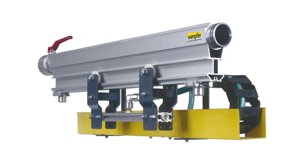
![]() Besta’Power
Besta’Power
Energy Guiding Chain W⁵-traxX
Order No. 0489xx-xxxx
Installation Instructions
General Notes
The instructions are a part of the device, and must be kept accessible to personnel at all times. Before starting work, operating personnel must read this manual carefully and understand it.
All products are subject to technical modifications in the context of improvement of function and further development.
Safety Instructions
The basic prerequisite for safe work is compliance with all safety and operating guidelines.
Local accident protection regulations and general safety guidelines for the area of use of the device also apply.
2.1 Explanation of Symbols
Safety instructions are identified in these instructions by symbols. Signal words are used to indicate the degree of hazard in these safety instructions. Always observe safety and hazard information and work carefully to avoid accidents, bodily harm or property damage!![]() WARNING!
WARNING!
… indicates a possibly hazardous situation, which if not avoided, may result in death or serious injury.![]() WARNING!
WARNING!
… indicates a possibly hazardous situation due to electrical current, which if not avoided, may result in death or serious injury.![]() CAUTION!
CAUTION!
… indicates a possibly hazardous situation, which if not avoided, may result in moderate or minor injury and property damage.
2.2 General Safety Regulations and Organization
In addition to the assembly instructions, general regulations regarding accident prevention and environmental protection are to be observed.
- Assembly, commissioning, maintenance and operation must be performed by sufficiently qualified and trained specialists.
- The assembly, maintenance and operational personnel must have read and understood the maintenance/assembly instructions and the safety regulations in particular. Protective equipment, such as such as protective gloves, safety shoes, work clothes and safety helmet, must be provided and worn.
- The system operator or his/her representative must supervise machine operation to ensure that personnel use caution when working on or with the system.
2.3 Specific Hazards
- Comply with safety and warning instructions to reduce health hazards and to avoid dangerous situations.
2.3.1 Electrical Hazards and Sources of Danger
| Danger of death by electrical shock | Live components and components that have become energized due to a malfunction can result in serious injury or death when touched. |
| Danger of injury by falling or being thrown after an electrical shock | → Installation, commissioning, maintenance, troubleshooting and decommissioning must be carried out by qualified electricians |
| → The powers supply must be disconnected and locked off before starting any work on the energy guiding chain | |
| → Electrical protection and grounding must be regularly checked by qualified electricians |
2.3.2 Mechanical Hazards and Sources of Danger
| Danger of crushing from moving components! | Careless operation of the equipment carrier can cause skin and fingers to be crushed. |
| → Do not reach into the chassis and rail area during movements | |
| → Wear protective gloves | |
| Risk of injury from falling or slipping! | There is a risk of slips and falls if the workspace is not free of obstacles and/or the adhesion of the floor is insufficient. |
| → Use robust, functioning ladders | |
| → Always keep the workspace free of obstacles | |
| → Keep the workspace clean |
Installation
![]() WARNING!
WARNING!
Danger of death by electrical shock!
Live components and components that have become energized due to a malfunction can result in serious injury or death when touched.
→ Installation, commissioning, maintenance, troubleshooting and decommissioning must be carried out by qualified electricians
→ The powers supply must be disconnected and locked off before starting any work on the energy guiding chain
→ Electrical protection and grounding must be regularly checked by qualified electricians
3.1 Preparations
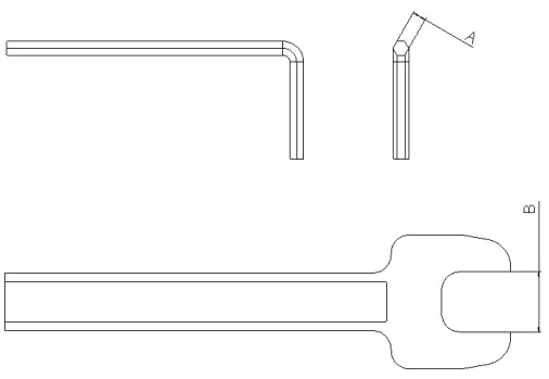
Tools needed:
| Installing the connecting plate | Pliers | |||||||||
| Installing the guide channel | Open-ended spanner, SW10 | |||||||||
| Installing the energy guiding chain and equipment carrier | Open-ended spanner, SW10; internal hex wrench, SW5 | |||||||||
 |
| |||||||||
| Fig. 1: Internal hex key (A) and open-ended wrench (B), spanner width | . |
3.2 Mounting Bracket
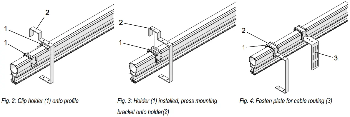
→ Clip the holder (1) onto the profile
→ Install the holder so that the pins are opposed to the matching holes. Push the two holders together
→ Press the mounting bracket (Item 2) onto the holder from above
→ Fasten the plate for cable routing (Item 3) in the same way
3.3 Guide Channel
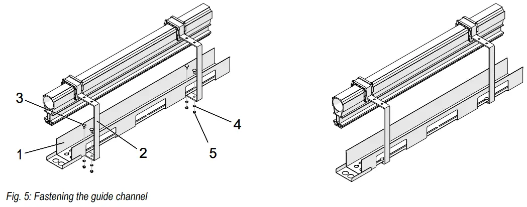
→ Fasten the guide channel (1) to the mounting bracket (2)
Fastening materials:
- DIN 603 round-headed bolts, M6x16 (3)
- DIN 125 washers, A6.4 (4)
- DIN 985 securing nuts, M6 (5)
→ Connect the guide channels, see Section 3.4
3.4 Connecting Plate
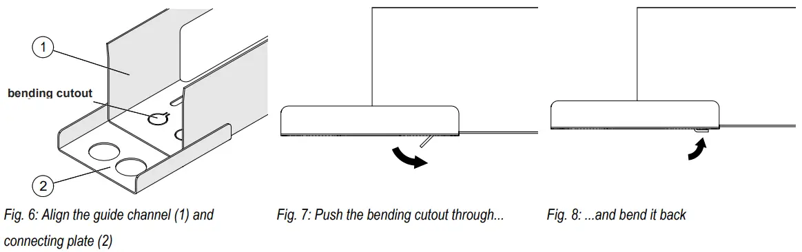
→ Locate the bending cutouts of the guide channel (1) over the holes in the connecting plate (2)
→ Use pliers to fold the bending cutouts down
3.5 Energy Guiding Chain
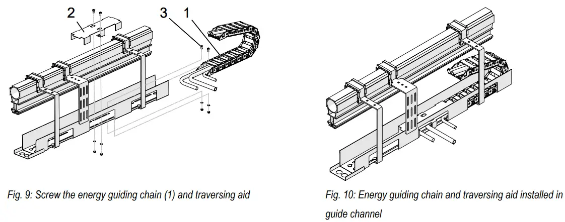
→ Place the energy guiding chain (1) in the guide channel and fix with screws.
Fastening materials:
- DIN 912 socket-head cap screws, M6x12 (3)
- DIN 125 washers, A6.4
- DIN 985 securing nuts, M6
→ Install the traversing aid (2) in the guide channel. For this, use the same fastening materials as for the energy guiding chain
3.6 Equipment Carrier![]() WARNING!
WARNING!
Danger of crushing from moving components!
Careless operation of the equipment carrier can cause skin and fingers to be crushed
→ Do not reach into the chassis and rail area during movements
→ Wear protective gloves
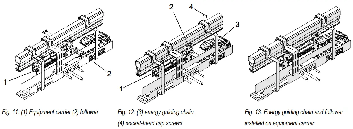
→ Install the follower (2) on the equipment carrier (1)
→ Push the equipment carrier (1) onto the profile
→ Screw the follower into the energy guiding chain (3)
Fastening materials:
- DIN 912 socket-head cap screws, M6x12 (4)
3.7 Connecting the Power Supply![]() WARNING!
WARNING!
Danger of death by electrical shock!
Live components and components that have become energized due to a malfunction can result in serious injury or death when touched.
→ Installation, commissioning, maintenance, troubleshooting and decommissioning must be carried out by qualified electricians
→ The powers supply must be disconnected and locked off before starting any work on the energy guiding chain
→ Electrical protection and grounding must be regularly checked by qualified electricians
→ Connect compressed air hose to the ball valve of the profile
→ Lay the compressed air hose on the cable-guiding plate and attach with cable ties
→ Trim the consumer end of the air hose according to the circumstances and connect it to the consumer
→ Connect the cables correctly to the power supply (the cable junction boxes and screw fixings supplied can be used for this)
→ Lay the cables correctly between the power-supply interface and chain
→ Trim the consumer ends of the cables according to the circumstances and connect it to the consumer
→ Lay the cables correctly between the consumer interface and the chain and secure
Arrange the components nozzle (1), hose clamp (2) and hose (3) as shown in Fig. 14:
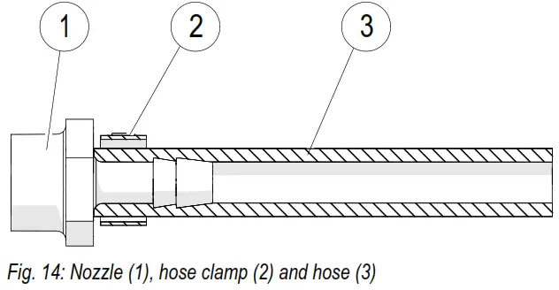
![]() CAUTION!
CAUTION!
Risk of damage to the hose!
If the hose clamp is mounted too tightly, the hose will be damaged.
→ Tighten the hose clamp only to such an extent that it cannot be moved any longer.
Commissioning
WARNING! Danger of death by electrical shock! Switch off the power supply and secure against reconnection.
- Have the electrical components and electrical protection checked by electricians
- Check for leaks in the compressed-air system
| Conductix-Wampfler GmbH Rheinstraße 27 + 33 79576 Weil am Rhein – Märkt Germany | Phone: +49 (0) 7621 662-0 Fax: +49 (0) 7621 662-144 [email protected] www.conductix.com |
 Importer for the United Kingdom: Importer for the United Kingdom:Conductix-Wampfler Ltd. 1, Michigan Avenue Salford M50 2GY United Kingdom | Phone: +44 161 8480161 Fax: +44 161 8737017 [email protected] www.conductix.com |
MV0489-0011b-EN
www.conductix.com


