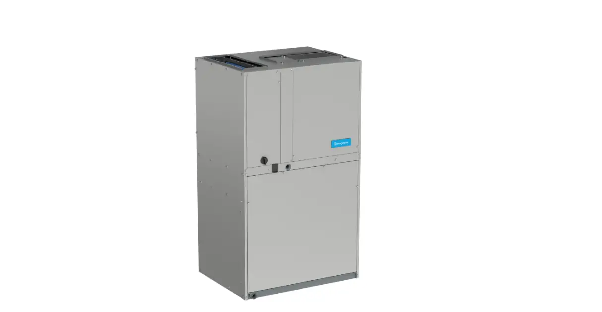
magicpak MCE4 Series Electric Cooling Heating Packaged Unit
Installation
WARNING
These units are not approved for mobile home applications. Such use could result in property damage, personal injury, or death.
General
These instructions explain the recommended method of installation of the Magic Pak All-In-One HVAC system model MCE4 electric cooling unit and associated electrical wiring. These instructions, and any instructions packaged with mating components and/or accessories. Note particularly any CAUTIONS or WARNINGS in these instructions and all labels on the units.
WARNING
Improper installation, adjustment, alteration, service or maintenance can cause property damage, personal injury or loss of life. Installation and service must be performed by a licensed professional installer (or equivalent), service agency or the gas supplier.
CAUTION
The installation of this appliance must conform to the requirements of the National Fire Protection Association; the National Electrical Code, ANSI/NFPA No. 70 (latest edition) in the United States; the Canadian Electrical Code Part 1, CSA 22.2 (latest edition) in Canada; and any state or provincial laws or local ordinances. Local authorities having jurisdiction should be consulted before installation is made. Such applicable regulations or requirements take precedence.
The MCE4 unit is a self-contained electric cooling unit with optional epoxy-coated coils. This unit has been examined for compliance with Canadian Standards Association CAN/CSA-C22.2 No. 236 (latest edition) and Underwriters Laboratories UL 1995. This unit is also in compliance with AHRI Performance Standard 210/240. Any alterations of internal wiring will void these listings and warranties. These instructions are intended as a general guide only, for use by qualified personnel and do not supersede any national or local codes in any way. Compliance with all local, state, provincial, or national codes pertaining to this type of equipment should be determined prior to installation. Units certified for less than 2% cabinet leakage using ANSI/ASHRAE 193 (complies with IECC 2015) are identified on the rating plate.
WARNING
Installation and servicing of air conditioning equipment can be hazardous due to internal refrigerant pressure and live electrical components. Only trained and qualified service personnel should install or service this equipment. Installation and service performed by unqualified persons can result in property damage, personal injury, or death. For your safety, do not store or use gasoline or other flammable vapors and liquids in the vicinity of this or any other appliance. Such actions could result in property damage, personal injury, or death. The unit must be installed with approved wall sleeve and louver accessories for safe operation. Improper installations could result in property damage, personal injury, or death. Refer to the Accessories section for additional details on wall sleeves and louvers.
Inspection
Upon receipt of equipment, carefully inspect it for possible shipping damage. If damage is found, it should be noted on the carrier’s freight bill. Take special care to examine the unit inside the carton if the carton is damaged. File a claim with the transportation company. If any damage is discovered and reported to the carrier, do not install the unit, as claim may be denied.
Check the unit rating plate to confirm specifications are as ordered.
Limitations
- The unit should be installed in accordance with all national and local safety codes.
- Limitations of the unit and appropriate accessories must also be observed.
- The outdoor fan is designed to operate against no more than 10 w.c. static pressure.
- Minimum and maximum operation conditions must be observed to assure proper system performance.
Ambient operating limitations of the unit
| Outdoor Ambient Air Temperature °F | ||
| Minimum DB | Maximum DB | |
| Cool | Cool | Heat |
| 65 | 115 | 75 |
| Indoor Ambient Air Temperature °F | |||
| Minimum | Maximum | ||
| DB/WB | DB | DB/WB | DB |
| Cool | Heat | Cool | Heat |
| 62/57 | 50 | 90/72 | 80 |
- DB = Dry Bulb
- WB = Wet Bulb
Ambient Temperature Limitations
Location
For information on wall sleeves and louver accessories, see the Accessories section. This unit is designed to be installed in up to the wall (exterior wall) installation only. The outside of the unit may be flush with the face of the exterior wall, and it should not be obstructed with trees, landscape materials, or building structure. Unit can be installed recessed with appropriate wall sleeve accessories. There is no minimum clearance required on locating the unit to an interior corner of a building. If the unit is installed in a residential garage, it must be located or protected to avoid physical damage by vehicles. The unit must be installed so that no electrical components are exposed to water.
CAUTIO
This unit must be installed level to allow for proper drainage of the unit base pan and indoor drain pan.
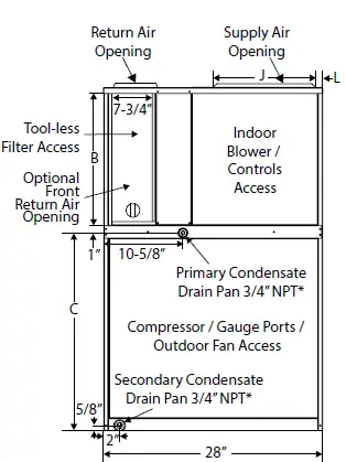
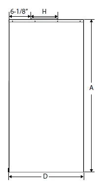
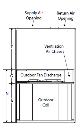
Unit Dimensions in
| Model | A | B* | C | D | E | F | G | H | J | K | L | M | N |
| MCE4-12-091*P MCE4-12-121*P MCE4-12-181*P | 43-7/8 | 16-7/8 | 25-1/4 | 21-1/2 | 18-5/8 | 19-1/4 | 6 | 8 | 16 | 17-1/16 | 3/4 | 2-1/4 | 24-5/8 |
| MCE4-12-241*P | 47-7/8 | 18-7/8 | 27-1/4 | 24-3/8 | 20-5/8 | 21-1/4 | 6 | 8 | 16 | 19-1/16 | 3/4 | 2-5/8 | 26-5/8 |
| MCE4-12-301*P | 55-7/8 | 22-7/8 | 31-1/4 | 24-3/8 | 24-5/8 | 25-1/4 | 6 | 11-3/8 | 10-7/16 | 22-7/16 | 3-3/4 | 1 | 30-5/8 |
| MCE4-14-361*P | 67-7/8 | 26-7/8 | 35-1/4 | 24-3/8 | 28-5/8 | 29-1/4 | 10 | 11-3/8 | 10-7/16 | 22-7/16 | 3-3/4 | 1 | 38-5/8 |
| Dimension B represents the height of the optional front return air duct opening | |||||||||||||
Top View
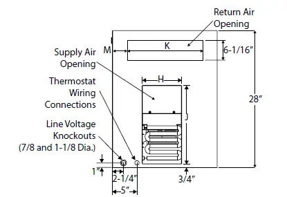
Front View
Side View
Rear View
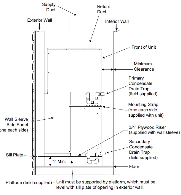
Provisions must be made to properly drain condensate from the primary and secondary drain pans.
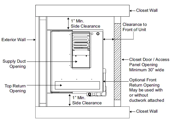
Accessibility Clearances
The front of the unit must be accessible for service. A minimum clearance of 30” in front of unit is required for service. If the unit is enclosed, a door or access panel aligned with the front of the unit is the preferred method of providing access. The door or access panel opening must be a minimum of 30 wide centered on the unit) and be as tall as the unit.
IMPORTANT
The unit must be installed with approved wall sleeve and louver accessories for safe operation. Improper installations could result in property damage, personal injury, or death.
Supply Duct Clearances
| Minimum Clearances to Combustible Materials1 | ||
| Front | Sides | Top |
| 0 | 0 | 0 |
1 Accessibility clearances take precedence
Unit Clearances
| Unit Clearances | Minimum Clearances1 | ||
| Return Duct Configuration | Unit Height | Front | Sides³ |
| Ducted Top Opening | All | Note 2 | 1 |
| Ducted Front Opening5 | All | Notes 2 & 4 | 1 |
| Non-Ducted/ Free Return | 43 | 4 | 1 |
| 48 – 68 | 5 | 1 | |
- Accessibility clearances take precedence.
- Clearance must accommodate field-installed condensate drain line / drain trap
- Additional clearance required if field-installed condensate drain line/drain trap is routed alongside unit
- Consult local codes for other clearance requirements
- If ductwork is attached to the optional front return.
- Consult local codes for other clearance requirements
- If ductwork is attached to the optional front return.
Top View
Side View
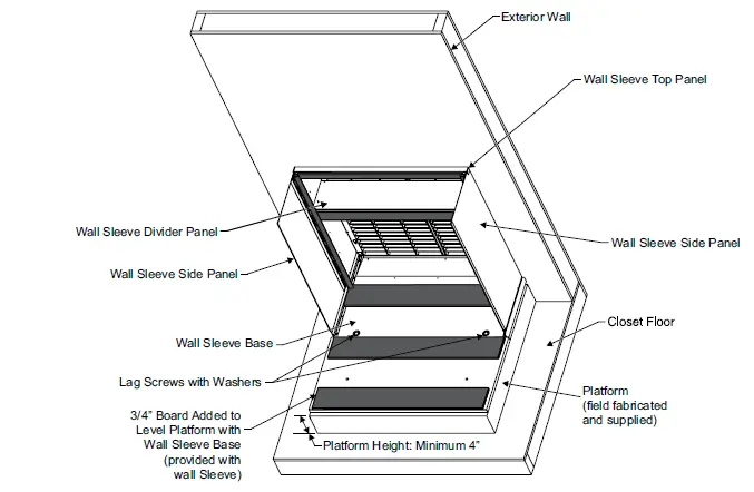
Wall Sleeve and Louver Kit Installation
NOTE
Unit must be supported by platform, which must be level with sill plate of opening in exterior wall.
CAUTION
The sleeve is not intended as the sole support for the unit. An additional support must be provided for adequate support.
Installing and Securing Unit to Wall Sleeve
- Before installing and securing the unit to the wall sleeve, make sure that the proper louver is installed.
- Make sure the gaskets attached to the sleeve are not damaged.
- Verify divider panel is positioned properly for wall sleeves that allow for multiple divider panel locations.
| Model | ASLEEVE2 | ASLEEVE-5 | Orientation of Flange |
| Two Positions | Three Positions | ||
| MCE4-12-09,12,18 | Lower | Lower | Down |
| MCE4-12-24 | Up | ||
| MCE4-12-30 | Upper | Middle | |
| MCE4-14-36 | N/A | Upper |
Place the unit into the wall sleeve. Lift leading end of unit and walk unit onto the sleeve. Once in the wall sleeve, lower the unit into position. This prevents damage to the base pads. Assure that the unit is level and completely seated against the gaskets on the wall sleeve. The unit must be supported by a field-supplied base platform.
Positioning Divider Panel
Flange Up Orientation
Flange Down Orientation
Securing Unit
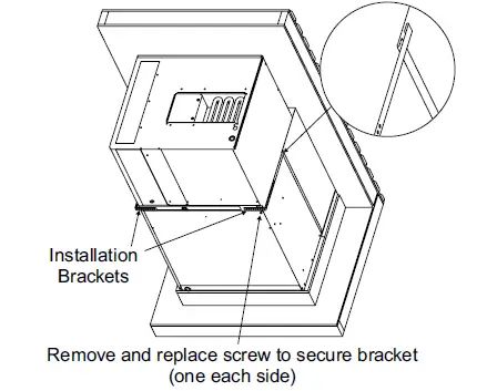
Use the two installation brackets to secure the unit to the wall sleeve. The units are shipped with the brackets placed in the return air compartment. Hook each bracket into the front edge of the wall sleeve side. Position the bracket so it can be bent around the front corner of the unit. Remove one of the two screws in that position on the unit. Line up one of the holes in the installation bracket with the screw hole and attach the bracket to the unit with that screw. Make sure to fasten tight enough that the seal is maintained. Trim off excess bracket if applicable.
CAUTION
Do not screw into the side of the drain pan, the indoor coil or the heat strip, which is located above the installation bracket. Inspect the fit up of the unit to the wall sleeve. Verify that the gaskets of the wall sleeve make a complete seal to the unit paying particular attention to top and bottom corners of unit to sleeve seal. Caulk if needed.
Ductwork
Ductwork should be designed and sized according to the methods in Manual Q of the Air Conditioning Contractors of America (ACCA). Check unit supply and return air outlets for debris before making ductwork connections. It is recommended that supply and return duct connections at the unit be made with flexible joints. If flexible ducts are used, a 6” sheet metal starter collar is required. The supply and return air duct systems should be fabricated per the designed CFM and static requirements of the job . Ductwork should not be sized to match the dimensions of the duct connections on the unit. The return duct should be sealed to the unit casing and terminate outside the space containing the unit.
Optional Front Return
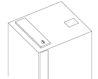
As shipped, units are configured for attaching supply and return ductwork to the top of the unit. Return air may be brought in through the optional front return opening. To open the optional front return and close off the top return opening, perform the following steps.
- Rotate knob to release filter access panel and remove panel.
- For all units except 3-ton models, position filter access panel to close off top return opening. Secure at rear using two sheet metal screws.
- Secure in front using knob.
- For 3-ton models, field fabricate a sheet metal panel to close off the top return opening.
- Seal panel to top of unit with tape or mastic.
NOTE
If ductwork is attached to the optional front return opening, provisions to service unit filter must be provided. Filter may need to be relocated to a suitable location outside the cabinet for ease of service.
Blower Performance (208V or 230V)
| Airflow Performance as a Function of External Static Pressure | |||||||||||||||||
| Model | Indoor Blower Speed | 0.1 w.c. | 0.2 w.c. | 0.3 w.c. | 0.4 w.c. | 0.5 w.c. | |||||||||||
| SCFM | Watts | HP | SCFM | Watts | HP | SCFM | Watts | HP | SCFM | Watts | HP | SCFM | Watts | HP | |||
| *MCE4-12-091*P | FAN | 355 | 28 | 0.04 | 320 | 31 | 0.04 | 275 | 35 | 0.05 | 230 | 38 | 0.05 | 160 | 42 | 0.06 | |
| COOL | 375 | 31 | 0.04 | 330 | 33 | 0.04 | 285 | 37 | 0.05 | N/A | N/A | N/A | N/A | N/A | N/A | ||
| COOL | N/A | N/A | N/A | N/A | N/A | N/A | 390 | 55 | 0.07 | 370 | 58 | 0.08 | 330 | 62 | 0.08 | ||
| 0 kW | TAP 4 HEAT | 375 | 31 | 0.04 | 330 | 33 | 0.04 | 285 | 37 | 0.05 | 240 | 40 | 0.05 | 180 | 44 | 0.06 | |
| TAP 5 HEAT | 465 | 47 | 0.06 | 425 | 51 | 0.07 | 390 | 55 | 0.07 | 370 | 58 | 0.08 | 330 | 62 | 0.08 | ||
| 3 kW | TAP 4 HEAT | 430 | 41 | 0.05 | 410 | 45 | 0.06 | 385 | 49 | 0.07 | N/A | N/A | N/A | N/A | N/A | N/A | |
| TAP 5 HEAT | 520 | 58 | 0.08 | 500 | 63 | 0.08 | 475 | 68 | 0.09 | 440 | 73 | 0.10 | 400 | 77 | 0.10 | ||
| 5 kW | TAP 4 HEAT | 525 | 59 | 0.08 | 505 | 65 | 0.09 | 480 | 69 | 0.09 | N/A | N/A | N/A | N/A | N/A | N/A | |
| TAP 5 HEAT | 615 | 81 | 0.11 | 590 | 88 | 0.12 | 560 | 94 | 0.13 | 530 | 99 | 0.13 | 500 | 103 | 0.14 | ||
| *MCE4-12-121*P | TAP 1 FAN | 355 | 28 | 0.04 | 320 | 31 | 0.04 | 275 | 35 | 0.05 | 230 | 38 | 0.05 | 160 | 42 | 0.06 | |
| TAP 2 COOL | 420 | 40 | 0.05 | 380 | 42 | 0.06 | 355 | 46 | 0.06 | N/A | N/A | N/A | N/A | N/A | N/A | ||
| TAP 3 COOL | N/A | N/A | N/A | 480 | 62 | 0.08 | 445 | 66 | 0.09 | 415 | 70 | 0.09 | 380 | 74 | 0.10 | ||
| 0 kW | TAP 4 HEAT | 420 | 40 | 0.05 | 380 | 42 | 0.06 | 355 | 46 | 0.06 | 315 | 50 | 0.07 | 275 | 54 | 0.07 | |
| TAP 5 HEAT | 515 | 58 | 0.08 | 480 | 62 | 0.08 | 445 | 66 | 0.09 | 415 | 70 | 0.09 | 380 | 74 | 0.10 | ||
| 3 kW | TAP 4 HEAT | 430 | 41 | 0.05 | 410 | 45 | 0.06 | 385 | 49 | 0.07 | N/A | N/A | N/A | N/A | N/A | N/A | |
| TAP 5 (HEAT) | 520 | 58 | 0.08 | 500 | 63 | 0.08 | 475 | 68 | 0.09 | 440 | 73 | 0.10 | 400 | 77 | 0.10 | ||
| 5 kW | TAP 4 HEAT | 525 | 59 | 0.08 | 505 | 65 | 0.09 | 480 | 69 | 0.09 | N/A | N/A | N/A | N/A | N/A | N/A | |
| TAP 5 HEAT | 615 | 81 | 0.11 | 590 | 88 | 0.12 | 560 | 94 | 0.13 | 530 | 99 | 0.13 | 500 | 103 | 0.14 | ||
| MCE4-12-181*P | TAP 1 (FAN) | 355 | 28 | 0.04 | 320 | 31 | 0.04 | 275 | 35 | 0.05 | 230 | 38 | 0.05 | 160 | 42 | 0.06 | |
| TAP 2 COOL | 660 | 103 | 0.14 | 640 | 109 | 0.15 | 610 | 114 | 0.15 | 580 | 119 | 0.16 | 550 | 124 | 0.17 | ||
| TAP 3 COOL | 725 | 131 | 0.18 | 710 | 135 | 0.18 | 685 | 140 | 0.19 | 660 | 146 | 0.20 | 640 | 152 | 0.20 | ||
| 0 kW | TAP 4 HEAT | 660 | 103 | 0.14 | 640 | 109 | 0.15 | 610 | 114 | 0.15 | 580 | 119 | 0.16 | 550 | 124 | 0.17 | |
| TAP 5 HEAT | 725 | 131 | 0.18 | 710 | 135 | 0.18 | 685 | 140 | 0.19 | 660 | 146 | 0.20 | 640 | 152 | 0.20 | ||
| 3 kW | TAP 4 HEAT | 430 | 41 | 0.05 | 410 | 45 | 0.06 | 385 | 49 | 0.07 | N/A | N/A | N/A | N/A | N/A | N/A | |
| TAP 5 HEAT | 520 | 59 | 0.08 | 500 | 63 | 0.08 | 475 | 67 | 0.09 | 440 | 72 | 0.10 | 400 | 77 | 0.10 | ||
| 5 kW | TAP 4 HEAT | 525 | 60 | 0.08 | 505 | 65 | 0.09 | 480 | 70 | 0.09 | N/A | N/A | N/A | N/A | N/A | N/A | |
| TAP 5 HEAT | 615 | 81 | 0.11 | 590 | 88 | 0.12 | 560 | 95 | 0.13 | 530 | 100 | 0.13 | 500 | 103 | 0.14 | ||
| 7 kW | TAP 4 HEAT | 685 | 108 | 0.14 | 670 | 116 | 0.16 | 645 | 122 | 0.16 | N/A | N/A | N/A | N/A | N/A | N/A | |
| TAP 5 HEAT | N/A | N/A | N/A | 770 | 160 | 0.21 | 750 | 166 | 0.22 | 720 | 172 | 0.23 | 700 | 177 | 0.24 | ||
| 10 kW | TAP 4 HEAT | N/A | N/A | N/A | 770 | 160 | 0.21 | 750 | 166 | 0.22 | N/A | N/A | N/A | N/A | N/A | N/A | |
| TAP 5 HEAT | N/A | N/A | N/A | N/A | N/A | N/A | N/A | N/A | N/A | 820 | 226 | 0.30 | 800 | 230 | 0.31 | ||
| N/A: Do not operate unit using this blower speed at this external static pressure. As shipped speed for Cooling operation. Blower speed must be field adjusted to Speed Tap 3 for higher duct static applications. As shipped speed for Heating operation. Blower speed must be field adjusted to Speed Tap 5 for higher duct static applications. | |||||||||||||||||
| Airflow Performance as a Function of External Static Pressure | |||||||||||||||||
| Model | Indoor Blower Speed | 0.1 w.c. | 0.2 w.c. | 0.3 w.c. | 0.4 w.c. | 0.5 w.c. | |||||||||||
| SCFM | Watts | HP | SCFM | Watts | HP | SCFM | Watts | HP | SCFM | Watts | HP | SCFM | Watts | HP | |||
| MCE4-12-241*P | TAP 1 FAN | 455 | 41 | 0.05 | 420 | 45 | 0.06 | 385 | 49 | 0.07 | 365 | 52 | 0.07 | 320 | 57 | 0.08 | |
| TAP 2 COOL | 810 | 146 | 0.20 | 790 | 158 | 0.21 | 780 | 166 | 0.22 | 755 | 173 | 0.23 | 735 | 179 | 0.24 | ||
| TAP 3 COOL | 870 | 179 | 0.24 | 860 | 184 | 0.25 | 845 | 194 | 0.26 | 815 | 202 | 0.27 | 785 | 206 | 0.28 | ||
| 0 kW | TAP 4 HEAT | 810 | 146 | 0.20 | 790 | 158 | 0.21 | 780 | 166 | 0.22 | 755 | 173 | 0.23 | 735 | 179 | 0.24 | |
| TAP 5 HEAT | 870 | 179 | 0.24 | 860 | 184 | 0.25 | 845 | 194 | 0.26 | 815 | 202 | 0.27 | 785 | 206 | 0.28 | ||
| 5 kW | TAP 4 HEAT | 555 | 65 | 0.09 | 540 | 69 | 0.09 | 510 | 73 | 0.10 | 480 | 76 | 0.10 | N/A | N/A | N/A | |
| TAP 5 HEAT | 645 | 88 | 0.12 | 630 | 94 | 0.13 | 605 | 100 | 0.13 | 580 | 105 | 0.14 | 550 | 110 | 0.15 | ||
| 7 kW | TAP 4 HEAT | 775 | 140 | 0.19 | 765 | 145 | 0.19 | 745 | 150 | 0.20 | 725 | 154 | 0.21 | N/A | N/A | N/A | |
| TAP 5 HEAT | 875 | 184 | 0.25 | 865 | 193 | 0.26 | 845 | 201 | 0.27 | 825 | 208 | 0.28 | 800 | 215 | 0.29 | ||
| 10 kW | TAP 4 HEAT | 875 | 184 | 0.25 | 865 | 193 | 0.26 | 845 | 201 | 0.27 | 825 | 208 | 0.28 | N/A | N/A | N/A | |
| TAP 5 HEAT | N/A | N/A | N/A | N/A | N/A | N/A | N/A | N/A | N/A | 960 | 272 | 0.36 | 900 | 276 | 0.37 | ||
| *MCE4-12-301*P | TAP 1 FAN | 590 | 42 | 0.06 | 530 | 48 | 0.06 | 430 | 55 | 0.07 | 380 | 60 | 0.08 | 315 | 65 | 0.09 | |
| TAP 2 COOL | 1015 | 152 | 0.20 | 985 | 161 | 0.22 | 940 | 170 | 0.23 | 910 | 177 | 0.24 | 875 | 184 | 0.25 | ||
| TAP 3 COOL | N/A | N/A | N/A | N/A | N/A | N/A | N/A | N/A | N/A | 1015 | 219 | 0.29 | 980 | 227 | 0.30 | ||
| 0 kW | TAP 4 HEAT | 1015 | 152 | 0.20 | 985 | 161 | 0.22 | 940 | 170 | 0.23 | 910 | 177 | 0.24 | 875 | 184 | 0.25 | |
| TAP 5 HEAT | N/A | N/A | N/A | N/A | N/A | N/A | N/A | N/A | N/A | 1015 | 219 | 0.29 | 980 | 227 | 0.30 | ||
| 5 kW | TAP 4 HEAT | 740 | 65 | 0.09 | 705 | 74 | 0.10 | 640 | 83 | 0.11 | N/A | N/A | N/A | N/A | N/A | N/A | |
| TAP 5 HEAT | 820 | 81 | 0.11 | 790 | 91 | 0.12 | 740 | 100 | 0.13 | 675 | 109 | 0.15 | 600 | 117 | 0.16 | ||
| 7 kW | TAP 4 HEAT | 860 | 91 | 0.12 | 835 | 100 | 0.13 | 795 | 108 | 0.14 | N/A | N/A | N/A | N/A | N/A | N/A | |
| TAP 5 HEAT | 945 | 112 | 0.15 | 925 | 122 | 0.16 | 885 | 132 | 0.18 | 845 | 140 | 0.19 | 800 | 148 | 0.20 | ||
| 10 kW | TAP 4 HEAT | 945 | 112 | 0.15 | 925 | 122 | 0.16 | 885 | 132 | 0.18 | N/A | N/A | N/A | N/A | N/A | N/A | |
| TAP 5 HEAT | N/A | N/A | N/A | N/A | N/A | N/A | 980 | 161 | 0.22 | 940 | 170 | 0.23 | 900 | 179 | 0.24 | ||
| *MCE4-14-361*P | TAP 1 FAN | 680 | 61 | 0.08 | 630 | 68 | 0.09 | 575 | 74 | 0.10 | 525 | 79 | 0.11 | 460 | 86 | 0.12 | |
| TAP 2 COOL | 1235 | 260 | 0.35 | 1200 | 272 | 0.36 | 1166 | 284 | 0.38 | 1135 | 295 | 0.40 | 1100 | 305 | 0.41 | ||
| TAP 3 COOL | N/A | N/A | N/A | N/A | N/A | N/A | 1250 | 330 | 0.44 | 1215 | 342 | 0.46 | 1180 | 354 | 0.47 | ||
| 0 kW | TAP 4 HEAT | 1235 | 260 | 0.35 | 1200 | 272 | 0.36 | 1166 | 284 | 0.38 | 1135 | 295 | 0.40 | 1100 | 305 | 0.41 | |
| TAP 5 HEAT | N/A | N/A | N/A | N/A | N/A | N/A | 1250 | 330 | 0.44 | 1215 | 342 | 0.46 | 1180 | 354 | 0.47 | ||
| 5 kW | TAP 4 HEAT | 740 | 75 | 0.10 | 695 | 82 | 0.11 | 640 | 90 | 0.12 | N/A | N/A | N/A | N/A | N/A | N/A | |
| TAP 5 HEAT | 815 | 92 | 0.12 | 785 | 100 | 0.13 | 745 | 108 | 0.14 | 700 | 115 | 0.15 | 650 | 122 | 0.16 | ||
| 7 kW | TAP 4 HEAT | 815 | 92 | 0.12 | 785 | 100 | 0.13 | 745 | 108 | 0.14 | N/A | N/A | N/A | N/A | N/A | N/A | |
| TAP 5 HEAT | 910 | 117 | 0.16 | 880 | 126 | 0.17 | 840 | 135 | 0.18 | 800 | 143 | 0.19 | 750 | 150 | 0.20 | ||
| 10 kW | TAP 4 HEAT | 1010 | 143 | 0.19 | 980 | 155 | 0.21 | 945 | 166 | 0.22 | N/A | N/A | N/A | N/A | N/A | N/A | |
| TAP 5 HEAT | 1085 | 175 | 0.23 | 1065 | 187 | 0.25 | 1030 | 198 | 0.27 | 995 | 209 | 0.28 | 950 | 219 | 0.29 | ||
| N/A: Do not operate unit using this blower speed at this external static pressure. As shipped speed for Cooling operation. Blower speed must be field adjusted to Speed Tap 3 for higher duct static applications. As shipped speed for Heating operation. Blower speed must be field adjusted to Speed Tap 5 for higher duct static applications. | |||||||||||||||||
Filter
All return air must be filtered. A washable filter is furnished with the unit, located in the return air compartment. If the optional front return opening is used and a duct is installed, provisions must be made to accommodate filter servicing. If a filter is installed at a separate central return location, then the factory furnished filter must be removed from the unit.
The washable filter may be replaced with a disposable filter. Avoid filter with paper frame and media; if it gets wet, it could collapse and block the coil, restricting airflow and causing issues with unit operation.
Filter sizes that fit the unit
| Model Number | Filter Size in |
| MCE4-12-09 MCE4-12-12 MCE4-12-18 | 18 x 20 x 1 |
| MCE4-12-24 | 20 x 22 x 1 |
| MCE4-12-30 | 22 x 24 x 1 |
| MCE4-14-36 | 22 x 28 x 1 |
When proper duct design is applied, field-provided filters up to MERV 6 can typically be installed in the unit’s factory filter location in lieu of a washable filter. If a higher resistance filter is field installed in the unit, the added resistance must be included in the external static pressure and must not exceed 0.5 in. w.c., including ductwork. If an installation is made in which it is more desirable to mount the filter exterior to the unit, in the return duct work or elsewhere, the washable filter can be used or replaced with a disposable filter. If a disposable filter is used, in lieu of washable filter, use the information provided when sizing the disposable filter.
Minimum Required Surface Area for Disposable Filters
| Model Number | Filter Area in2 |
| MCE4-12-09 MCE4-12-12 | 250 |
| 0MCE4-12-18 3MCE4-12-18 5MCE4-12-18 | 310 |
| 7MCE4-12-18 10MCE4-12-18 | 380 |
| MCE4-12-24 | 420 |
| MCE4-12-30 | 480 |
| MCE4-14-36 | 575 |
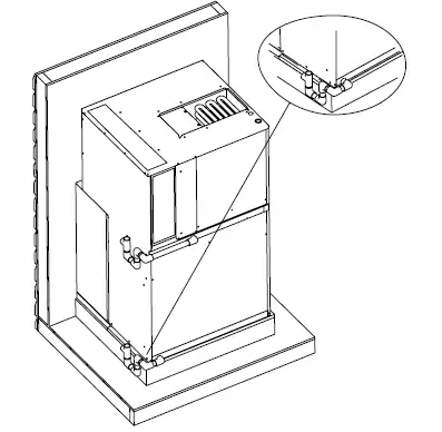
Condensate Drain
Provisions must be made to properly drain the primary and secondary drain pans of this appliance. Primary drain and secondary drain connection: 3/4 NPT to 3/4 PVC fitting schedule 40 minimum. Both drains must be trapped. The drain line should pitch gradually downward at least 1 per 10’ of horizontal run to an open drain. If local codes require the use of metal condensate lines, do not thread metal fittings into the unit drain pans. Thread a PVC fitting into the unit drain pans and make the field connection to the PVC fitting.
NOTE
These units are designed with a redundant drain system to handle condensate without the need for an emergency drain pan. Should the indoor coil condensate drain system fail, all water is contained within the unit and the flow is directed into the unit base pan. From there it will drain into the condensate riser. If for some reason the water cannot drain into the main condensate riser, all water is contained in the unit, and the design will allow drainage out through the wall sleeve and louver to the outside of the building.
CAUTION
Use thread sealant on the threaded fittings. Install threaded fittings by hand only. Do not over torque the fittings. Do not thread metal condensate fittings to unit drain pans.
Condensate Drain Installation
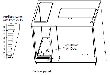
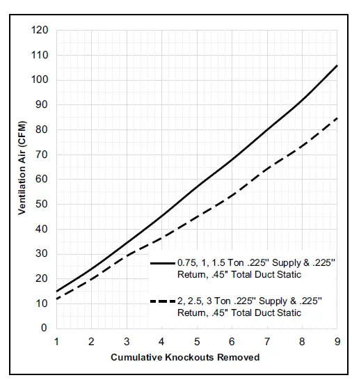
Ventilation Air
Units ship with a panel installed that seals the return air compartment at the ventilation air intake. Installers can choose to remove the factory-installed panel and use the field-provided ventilation damper if introduction of ventilation air is desired.
NOTE
If ventilation air is introduced, the quantity of air and conditions of this air must be accounted for in the load calculations. The auxiliary panel has nine knockouts to configure ventilation air flow to installation requirements to determine which knockouts to remove from the auxiliary panel in order to achieve the desired ventilation air flow. Use a flat head screw driver to remove the knockouts. Set the factory-installed panel aside for possible future changes.
WARNING
The location of ventilation air capable models must conform to the requirements of National Fire Protection Association NFPA No. 54 in regards to proximity of forced air inlets to flue gas terminals. Improper installation could result in personal injury or death.
Auxiliary and Factory Panel for Ventilation Air
| Ventilation Air CFM | ||||||
| Cumulative Knockouts Removed | Total External Static Pressure supply + return | |||||
| 0.1 | 0.2 | 0.3 | 0.4 | 0.5 | ||
| 0.75, 1.0, 1.5 TON | # 1 Only | 7 | 9 | 12 | 15 | 18 |
| #1 thru #2 | 10 | 15 | 20 | 24 | 28 | |
| #1 thru #3 | 12 | 18 | 25 | 32 | 38 | |
| #1 thru #4 | 18 | 28 | 36 | 45 | 54 | |
| #1 thru #5 | 23 | 35 | 46 | 57 | 69 | |
| #1 thru #6 | 27 | 41 | 54 | 67 | 80 | |
| #1 thru #7 | 32 | 48 | 63 | 78 | 93 | |
| #1 thru #8 | 37 | 55 | 73 | 90 | 107 | |
| #1 thru #9 | 41 | 61 | 80 | 100 | 118 | |
| 2.0, 2.5, 3.0 TON | # 1 Only | 21 | 20 | 19 | 17 | 16 |
| #1 thru #2 | 28 | 27 | 25 | 24 | 22 | |
| #1 thru #3 | 35 | 33 | 32 | 30 | 28 | |
| #1 thru #4 | 45 | 42 | 40 | 38 | 35 | |
| #1 thru #5 | 55 | 52 | 49 | 46 | 43 | |
| #1 thru #6 | 66 | 62 | 59 | 55 | 52 | |
| #1 thru #7 | 79 | 75 | 71 | 66 | 62 | |
| #1 thru #8 | 91 | 86 | 81 | 76 | 71 | |
| #1 thru #9 | 105 | 99 | 94 | 88 | 82 | |
| Assumes proper speed tap adjustments to maintain nominal supply air CFM Assumes equal supply and return static pressures | ||||||
Thermostat
The room thermostat should be located on an inside wall where it will not be subject to drafts, sun exposure, or heat from electrical fixtures or appliances enclosed with the thermostat for general installation procedures. Color-coded insulated wires (#18 AWG) should be used to connect the thermostat to the unit.
Electrical Connections
The unit must be electrically grounded in accordance with local codes or, in the absence of local codes, with the National Electrical Code ANSI/NFPA. Any alteration of internal wiring will void certification and warranty. Units are factory wired for a 230 volt power supply. If power supply is 208 volts, it will be necessary to change a wire connection on unit transformer from 240 volt terminal to 208 volt terminal. Use wiring with a temperature limitation of 75°F minimum. Run the 208 or 230 volt, single phase, 60 hertz electric power supply through a fused disconnect switch to the control box of the unit and connect. The power supply to the unit must be NEC Class 1 and must comply with all applicable codes. A fused disconnect switch should be field provided for the unit, and must be separate from all other circuits. If any of the wire supplied with the unit must be replaced, replacement wire must be of the type. Electrical wiring must be sized to minimum circuit ampacity (MCA) marked on the unit. Use copper conductors only. Each unit must be wired with a separate branch circuit and be properly fused.
Operation
Sequence of Operation
Upon initial power up to unit, there is a 3-minute time delay to the compressor contactor R to Y. Any 24V interrupt R, C to the defrost control will initiate the 3-minute delay to the contactor.
Cooling
When the thermostat is in the cooling mode, the O circuit is powered which energizes the reversing valve. Upon cooling demand, the thermostat closes circuit R to Y and G. Closing R to Y closes the unit contactor, starting the compressor and outdoor fan, and signaling the indoor blower to run at cooling speed. Upon satisfying cooling demand, the thermostat will open the above circuits and open the main contactor, stopping the compressor and outdoor fan. The unit is equipped with a blower OFF delay; the blower will continue to operate for a fixed 90 seconds after the thermostat is satisfied.
Heating
Upon heating demand, the thermostat closes circuit R to W. On units supplied with heat strips, the sequencers are then energized and bring on the auxiliary electric heat. Units with no factory heat installed contain an auxiliary heat relay that will close, energizing the 24VAC output. This output can be used to control (not power) an auxiliary heat source. The W signal from the thermostat brings the indoor blower on at electric heat speed. Upon satisfying heating demand, the thermostat opens the above circuits and stops unit operation. The unit is equipped with a blower OFF delay the blower will continue to operate for a fixed 120 seconds (electric heat) after the thermostat is satisfied.
NOTE
The 7.2 and 10 kW heats strips offer a W1 and W2 thermostat connection. Taking advantage of the two heat strip circuits requires a 2 stage thermostat W1 for electric heat stage 1 and W2 for electric heat stage 2. If a single stage thermostat is used pigtail W1 and W2 wires together when connecting the thermostat wires at the unit.
Maintenance
WARNING
Disconnect all electrical power to the unit before conducting any maintenance procedures. Failure to disconnect the power could result in personal injury or death. There frigeration system normally requires no maintenance since it is a closed, self-contained system. Periodic inspection and maintenance normally consists of changing or cleaning filters and under some conditions cleaning the coils.
Filter
Inspect the filter once a month. Replace disposable filter or clean the washable filter as necessary (a minimum of three times each heating or cooling season is recommended).
To clean the washable filter, shake filter to remove excess dirt and/or use a vacuum cleaner. Wash filter in soap or detergent water and replace after filter is dry.
Motors
The indoor and outdoor fan motors are permanently lubricated and require no maintenance.
Outdoor Coil
Foreign material should not be allowed to accumulate on the outdoor coil surface or other parts in the air circuit. Cleaning should be as often as necessary to keep the coil clean. To clean the coil, remove the lower access panel and blow out debris by using compressed air or water. Be sure power to unit is shut off before using water to clean the coil.
Care should be used when cleaning the coils so that the coil fins are not damaged.
Primary and Secondary Condensate Drain
Foreign material should not be allowed to clog the drain hole. Inspect and clear drain opening prior to each heating and cooling season.
Accessories
WARNING
The unit must be installed with approved wall sleeve and louver accessories for safe operation. Improper installations could result in property damage, personal injury, or death.
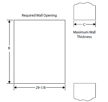
Dimension information
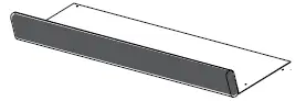
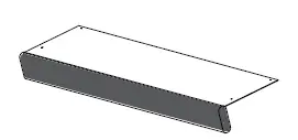
Wall Sleeve
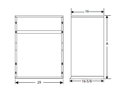
Exterior Wall
| Wall Sleeves | Louvers | Model | Dimensions (in.) | |||||||||||
| Wall Sleeve | Wall Opening | |||||||||||||
|
Wall Sleeve |
Wall Sleeve Extension |
Polypropylene Louvers |
Aluminum Louvers |
Impact Louvers | MCE4-12-091 P | MCE4-12-121 P | MCE4-12-181 P | MCE4-12-241 P | MCE4-12-301 P | *MCE4-14-361 P |
Height A |
Height B | Depth (C) | |
| Sleeve Only | Sleeve Plus Extension | |||||||||||||
| ASLEEVE6-1 | ALVRP***-1 | ALVRAL-1^ | ALVRALC-1^ | 29 | 29-1/8 | 6 | ||||||||
| ASLEEVE8-1 | ALVRP***-1 | ALVRAL-1^ | ALVRALC-1^ | 29 | 29-1/8 | 8 | ||||||||
| ASLEEVE10-1 | ASLEEVEXT4-1 | ALVRP***-1 | ALVRAL-1^ | ALVRALC-1^ | 29 | 29-1/8 | 10 | 14 | ||||||
| ASLEEVE12-1 | ASLEEVEXT4-1 | ALVRP***-1 | ALVRAL-1^ | ALVRALC-1^ | • | • | 29 | 29-1/8 | 12 | 16 | ||||
| ASLEEVE6-2 | ALVRP***-2 | ALVRAL-2^ | ALVRALC-2^ | • | 32-3/4 | 32-7/8 | 6 | |||||||
| ASLEEVE8-2 | ALVRP***-2 | ALVRAL-2^ | ALVRALC-2^ | • | 32-3/4 | 32-7/8 | 8 | |||||||
| ASLEEVE10-2 | ASLEEVEXT4-2 | ALVRP***-2 | ALVRAL-2^ | ALVRALC-2^ | • | 32-3/4 | 32-7/8 | 10 | 14 | |||||
| ASLEEVE12-2 | ASLEEVEXT4-2 | ALVRP***-2 | ALVRAL-2^ | ALVRALC-2^ | • | 32-3/4 | 32-7/8 | 12 | 16 | |||||
| ASLEEVE6-2 | ALVRP***-2 | ALVRAL-7^ | ○ | ○ | ○ | ○ | 32-3/4 | 32-7/8 | 6 | |||||
| ASLEEVE8-2 | ALVRP***-2 | ALVRAL-7^ | ○ | ○ | ○ | ○ | 32-3/4 | 32-7/8 | 8 | |||||
| ASLEEVE10-2 | ASLEEVEXT4-2 | ALVRP***-2 | ALVRAL-7^ | ○ | ○ | ○ | ○ | 32-3/4 | 32-7/8 | 10 | 14 | |||
| ASLEEVE12-2 | ASLEEVEXT4-2 | ALVRP***-2 | ALVRAL-7^ | ○ | ○ | ○ | ○ | 32-3/4 | 32-7/8 | 12 | 16 | |||
| ASLEEVE6-5 | ALVRP***-3 | ○ | ○ | ○ | ○ | ○ | • | 45 | 45-1/8 | 6 | ||||
| ASLEEVE8-5 | ALVRP***-3 | ○ | ○ | ○ | ○ | ○ | • | 45 | 45-1/8 | 8 | ||||
| ASLEEVE10-5 | ASLEEVEXT4-3 | ALVRP***-3 | ○ | ○ | ○ | ○ | ○ | • | 45 | 45-1/8 | 10 | 14 | ||
| ASLEEVE12-5 | ASLEEVEXT4-3 | ALVRP***-3 | ○ | ○ | ○ | ○ | ○ | • | 45 | 45-1/8 | 12 | 16 | ||
| ASLEEVE6-5 | ALVRAL-3^ | ALVRALC-3^ | ○ | ○ | ○ | ○ | 45 | 45-1/8 | 6 | |||||
| ASLEEVE8-5 | ALVRAL-3^ | ALVRALC-3^ | ○ | ○ | ○ | ○ | 45 | 45-1/8 | 8 | |||||
| ASLEEVE10-5 | ASLEEVEXT4-3 | ALVRAL-3^ | ALVRALC-3^ | ○ | ○ | ○ | ○ | 45 | 45-1/8 | 10 | 14 | |||
| ASLEEVE12-5 | ASLEEVEXT4-3 | ALVRAL-3^ | ALVRALC-3^ | ○ | ○ | ○ | ○ | 45 | 45-1/8 | 12 | 16 | |||
| ASLEEVE6-5 | ALVRAL-4^ | ALVRALC-4^ | ○ | • | 45 | 45-1/8 | 6 | |||||||
| ASLEEVE8-5 | ALVRAL-4^ | ALVRALC-4^ | ○ | • | 45 | 45-1/8 | 8 | |||||||
| ASLEEVE10-5 | ASLEEVEXT4-3 | ALVRAL-4^ | ALVRALC-4^ | ○ | • | 45 | 45-1/8 | 10 | 14 | |||||
| ASLEEVE12-5 | ASLEEVEXT4-3 | ALVRAL-4^ | ALVRALC-4^ | ○ | • | 45 | 45-1/8 | 12 | 16 | |||||
| Note: Wall Sleeve and Louver size must be coordinated *** Louver colors: WHT = white, SAN = sandstone, BGE = beige, TPST = taupe stone ^ -P: Option to paint standard, aluminum, and impact-resistant louvers • Wall sleeve and louver sizes equal to the required wall opening dimensions for the unit size ◦ Optional: Wall sleeves and louvers can be oversized to maintain a uniform appearance | ||||||||||||||
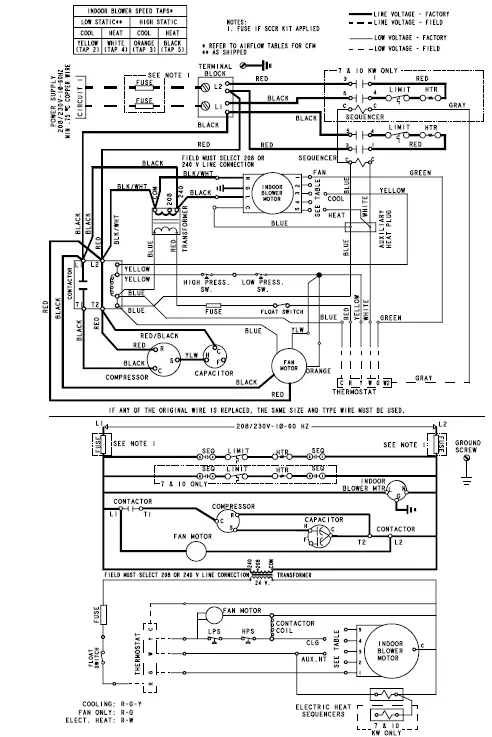
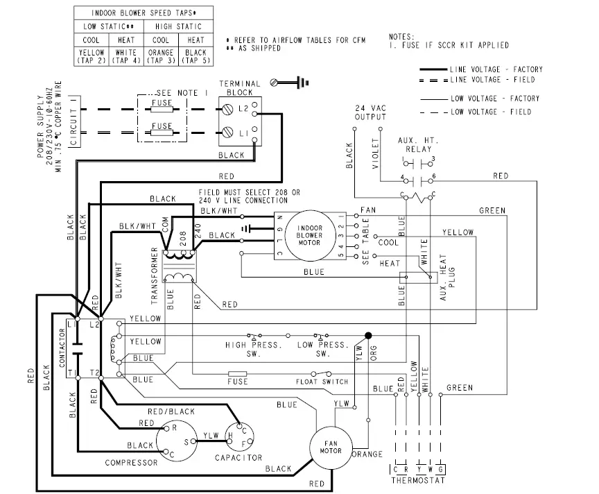
Wiring Diagrams
MCE without Electric Heat 0.75 Ton through 2.5 Ton
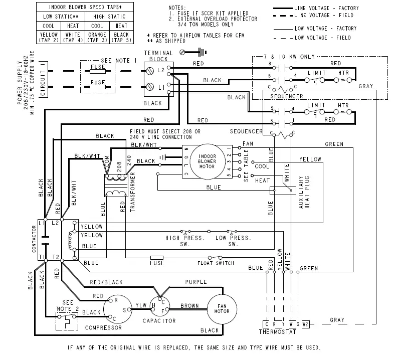
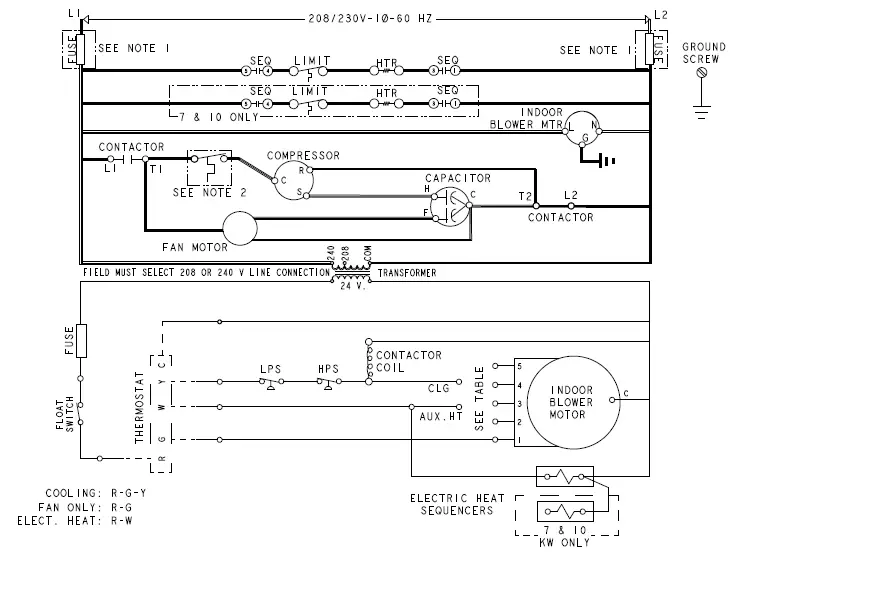
MCE with Factory-Installed Electric Heat 0.75 Ton through 2.5 Ton
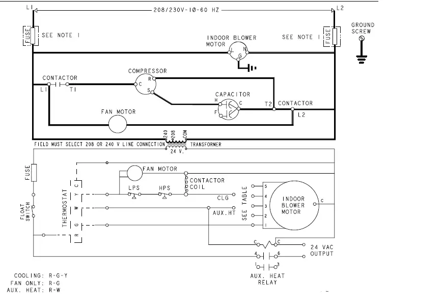
Wiring Diagram MCE without Electric Heat 3 Ton
Wiring Diagram MCE with Factory-Installed Electric Heat 3 Ton