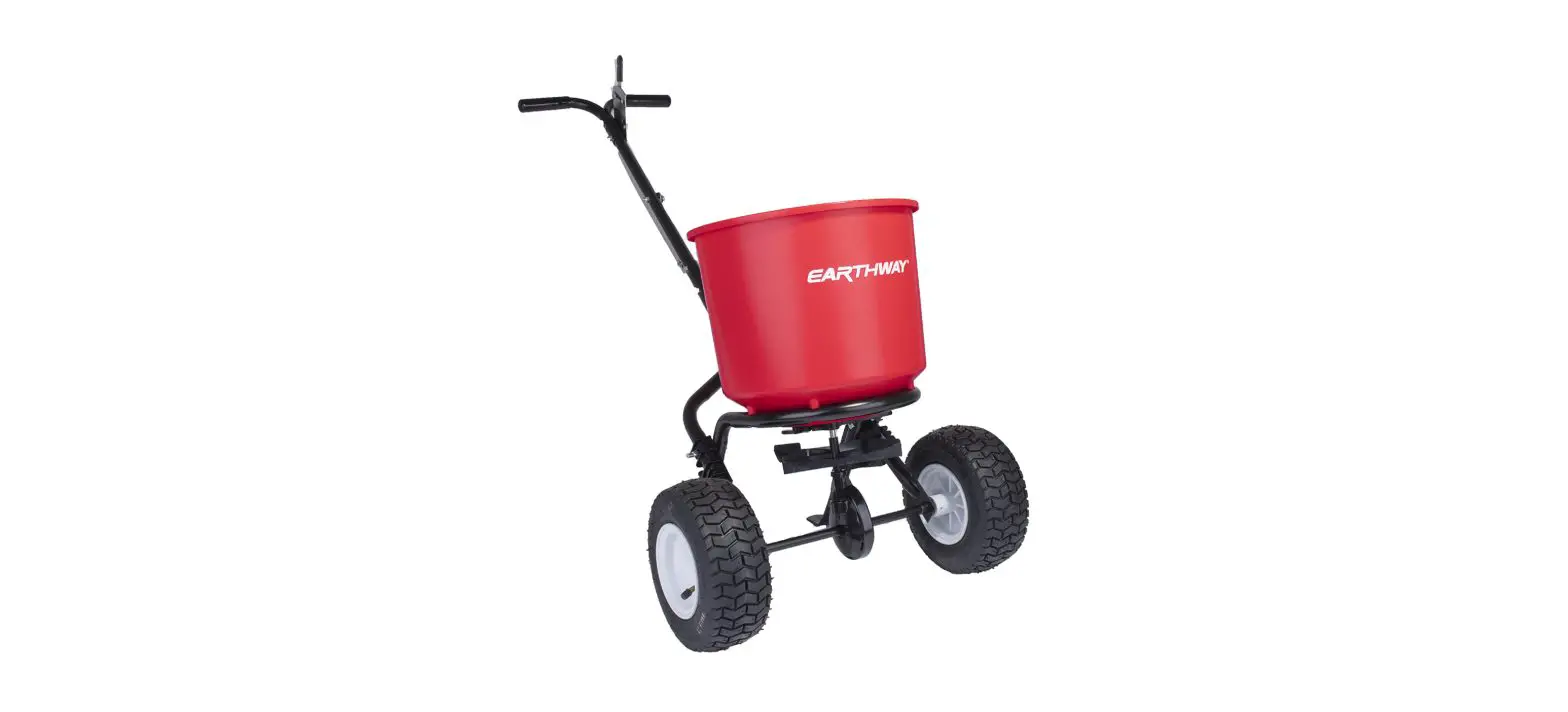
EARTHWAY 2600A-Plus Estate Broadcast Spreader Instruction Manual
HELPFUL HINTS
- Make sure the ARROW on the gear box points to the front of the spreader. The impeller must turn clockwise. Reversing the gearbox will cause the impeller to turn counter clockwise. Clean the impeller plate after each use. Fertilizer stuck on the impeller blades will cause uneven spreading.
- Your spreader is designed to be pushed at three miles per hour, which is a brisk walking speed. Slower or faster speeds will change the spread patterns. Wet fertilizer will also change the spread pattern and flow rate. Clean and dry your spreader thoroughly after each use. A coating of light spray oil on all metal parts will help prevent corrosion, pay special attention to coating the inside of the steel tubing.
Gears are permanently lubricated at the factory. Do not open the gearbox or dirt may enter.
ASSEMBLY INSTRUCTIONS
Thank you for selecting Earth Way for your spreader needs. Our production team in Northern Indiana takes pride in building this spreader. Our customer support team is standing ready to ensure your success. Please contact us at www.EarthWay.com to see our full line of commercial, lawn & garden tools.
Note: Your Earth Way spreader includes a feature called side spread control. This feature turns off fertilizer from being spread to the left side. To activate this feature, slide the lever below the hopper to the right (if standing behind the spreader) and walk along a sidewalk or flowerbed that is 12”-14” on your left side. Fertilizer will not spread to the left. This feature is better than a deflector as no material is wasted by the deflector.
For spreading, please utilize the following spreader settings:
Spreader | Lbs sq | Grams sq |
| 11 | 1.1 | 5 |
| 13 | 2.0 | 10 |
| 14 | 3.0 | 15 |
| 16 | 4.0 | 20 |
| 17 | 5.0 | 25 |
| 18 | 6.0 | 30 |
| 19 | 7.0 | 35 |
| 20 | 8.0 | 40 |
| 22 | 9.0 | 45 |
| 13 | 10.0 | 50 |
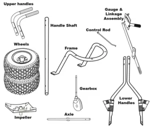
ASSEMBLY INSTRUCTIONS
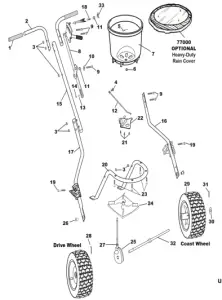
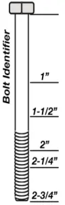
- Remove and identify all loose parts from carton
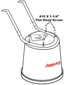
- Position hopper as shown to the right. Install frame using (4) #10 x 1 ¼” Flat Head Phillips screws. TIGHTEN THESE NOW


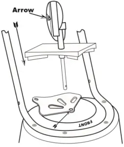
- . Install gear box by inserting the pinion shaft into hole in center of hoppers bottom. The ARROW on the gearbox must point to FRONT of the hopper. Follow label instructions on hopper.

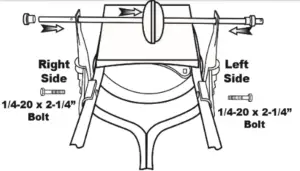
- . Install lower handles onto Frame and secure with ¼-20 x 2¼” bolt through hole in Frame Braces and through the hole in frame.
Warning Remove agitator when using Rock Salt to prevent gearbox damage.
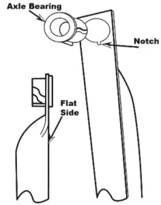
Next, SLIDE THE AXLE (COAST WHEEL SIDE FIRST) through the right side lower handle and into the gearbox (with the arrow facing the FRONT), you will need to rotate the axle to engage with the gearbox, then through the left side lower handle.

- Install the bearings over the axle and press into the notches of the lower handle as shown to the left.
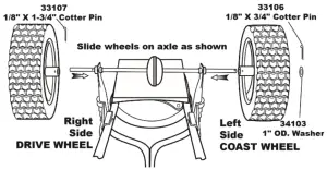
IMPORTANT - Install drive wheel to axle using pin hole nearest to lower handles as shown. Insert 1 ¾” Cotter pin through wheel and through axle. Bend with pliers to prevent pin from falling out.

- Install coast wheel to axle using outside pin hole. As shown, add the flat washer, and insert ¾” Cotter pin through axle (not thru wheel). Bend with pliers to prevent pin from falling out.
- TURN SPREADER UPRIGHT ON TO WHEELS.
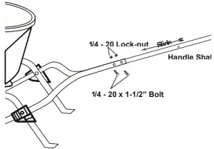
Install Handle Shaft as shown below using (2) ¼-20 x 1 ½” Hex Bolt and (2) ¼-20 Locknuts.
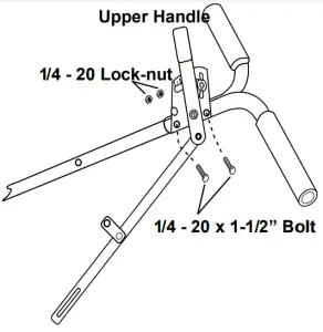
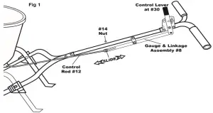
- Insert (2) ¼-20 x 1 ½” Hex bolt through Gauge and Linkage Assembly, then through the Upper Handle, Handle Shaft, Upper Handle and secure with (2) ¼-20 Locknuts as shown to the right.

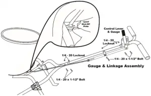
- Attach Linkage Pivot with ¼-20 x 1 ½” Hex Bolt, Flat Washer, Spacer and Locknut as shown below. Next, install Control Rod into the Shut-Off Plate as shown at the right. TIP: Make sure that the Control Rod is above the Lower Handles.

- Using ½” Carriage Bolt, install through the Control Rod, Linkage and install the Flat Washer and secure with Hex Nut to a loose fit to allow for CALIBRATION below. See above, right, and below for details.

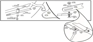
- CALIBRATION: THIS STEP ENSURES THAT YOUR SPREADER IS PROPERLY ADJUSTED TO GIVE YOU A CORRECT STARTING POINT TO APPLY MATERIALS AT THE CORRECT SETTING. Pull the Control Lever back to #30 on the Gauge, then push the shut-off plate forward until the shut-off and the drop holes are full open. Now tighten the Hex Nut on the ½” Carriage Bolt on the Linkage Assembly. Check to confirm calibration by closing the Control Lever, then reopening to #30 and confirm that the drop holes are fully open.

- Insert agitator to pinion shaft on inside of hopper. NOTE: Position of flat side of the agitator as shown at the right.

OPERATING INSTRUCTIONS
Before filling hopper, become familiar with the operation of this spreader.
- Obtain proper setting for material to be used from the RATE SETTING MATRIX included with this spreader.
- Move stop bolt on rate gauge assembly to the proper setting for the material that you are spreading.
- While pushing spreader forward, pull the Control Lever back to stop bolt.
- To stop, push lever forward to close flow holes before you stop moving.
- When finished, empty any remaining material from hopper.
- Thoroughly wash spreader and allow to dry before storing. Spray all metal surfaces (inside & outside) with WD40 or other light oil to help prevent corrosion.


HOW TO ORDER SPARE PARTS
All spare parts listed herein may be ordered direct from the manufacturer. Be sure to give the following information when ordering.
- Model Number
- Part Number
- Part Description
You can contact us by calling (574) 848-7491 to place an order with a credit card, or purchase online at https://www.earthway.com/product-category/parts/ Questions? Email us at [email protected]
2600APlus Broadcast Spreader Parts List
2600APlus Broadcast Spreader Parts List | |||||
| Key # | Part # | Description Key # Part # Description | |||
| 1 | 19115 | .875″ ID. X 4″ IL. BLACK GRIP | 18 | 37100 | 1/4-20 X 1″ CARRIAGE BOLT ZINC |
| 2 | 25403 | UPPER HANDLE | 19 | 31106 | 1/4-20 X 2 1/4″ HHCS ZINC |
| 3 | 32103 | 1/4-20 NYLON INS LOCKNUT ZINC | 20 | 25107 | FRAME |
| 4 | 36500 | #10-24 X 1/2″ CARRIAGE BOLT SS | 21 | 31138 | #8 X 3/8″ PMT #8 HD COARSE BLACK |
| 5 | 33117 | AGITATOR | 22 | 12221 | New SSC SHUT OFF PLATE |
| 6 | 12220 | GEAR BOX BUSHING | 23 | 31108 | #10 X 1 1/4″ TYPE A FHPS ZINC |
| 7 | 60089 | HOPPER ASSEMBLY | 24 | 12248 | IMPELLER DISHED |
| 8 | 60088 | GAUGE & LINKAGE ASSEMBLY | 25 | 60451 | GEAR BOX ASSEMBLY |
| 9 | 31100 | 1/4-20 X 1 1/2 HHMS ZINC | 26 | 12167 | SPACER BEARING |
| 10 | 34108 | 9/16″ OD. X .257 ID. WASHER ZINC | 27 | 12206 | DUST COVER (GEAR BOX) RND |
| 11 | 12147 | SPACER | 28 | 33107 | 1/8″ X 1 3/4″ COTTER PIN S.S. |
| 12 | 41256 | CONTROL ROD | 29 | 70149 | 9 IN PNEUMATIC WHEEL |
| 13 | 34100 | #10 FLAT WASHER SS | 30 | 34103 | 1″OD X 17/32″ID X 1/32″ WASHER ZINC |
| 14 | 32108 | 10-24 HX. NUT ZINC PLATED | 31 | 33106 | 1/8″ X 3/4″ COTTER PIN ZINC |
| 15 | 25304 | HANDLE SHAFT | 32 | 23519 | AXLE |
| 16 | 25210L | LOWER HANDLE Assembly – Left | 33 | 60027 | WING NUT ASSEMBLY BLACK |
| 17 | 25210R | LOWER HANDLE Assembly – Right | |||
CUSTOMER SERVICE
574.848.7491 | [email protected] | www.EARTHWAY.com | 1009 Maple Street, Bristol, IN 46507
ONE YEAR WARRANTY
Earth Way Products, Inc. warrants this product free of defects in original workmanship and materials for a period of one year to the end user with
the original purchase receipt. If a manufacturing non-conformance is found, Earth Way Products, Inc. at its discretion will repair or replace the part(s)/product at no charge provided the failure is not the result of incorrect installation, mishandling, misuse, tampering, or normal wear and tear as determined by Earth Way.
Earth Way at its discretion may require that the part(s) or product be returned along with the original purchase receipt for examination and compliance with the terms of this warranty. Do not return any product without first receiving authorization from Earth Way Products, Inc.
To seek remedy under this warranty, contact Earth Way Products, Inc. at 574-848-7491, [email protected] or write to Earth Way Products, Inc. 1009 Maple Street, Bristol, IN 46507 and describe the nature of the manufacturing defect. SPECIFIC LIMITATIONS : This warranty covers only the part(s) or product; any labor charges associated with repair or replacement of non-conformances are specifically excluded. Due to the corrosive nature of most fertilizers and ice melt products, Earth Way Products, Inc. makes no warranty against and specifically excludes part(s) or product degradation or failure due to corrosion or its effects.
![]()


