Commercial Electric WRAP2C840IRMM/HD/CAN 2 FT LED Wrap Utility Light with Motion Sensor and Remote User Guide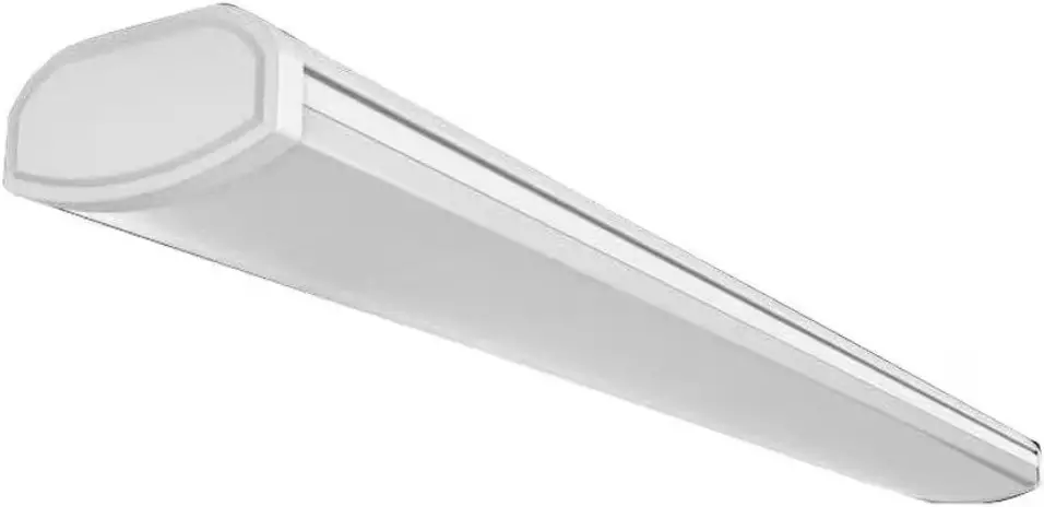
THANK YOU
We appreciate the trust and confidence you have placed in Commercial Electric through the purchase of this LED utility fixture.
We strive to continually create quality products designed to enhance your home. Visit us online to see our full line of products available for your home improvement needs. Thank you for choosing Commercial Electric!
Safety Information
For your safety, always remember to:
- Double-check all connections to be sure they are tight and correct.
- Wear rubber soled shoes and work on a sturdy wooden ladder.
- Account for small parts and destroy packing material, as these may be hazardous to children.
 NOTE: This xture is designed for use in a circuit protected by a fuse or circuit breaker. It is also designed to be installed in accordance with local electrical codes. If you are unsure about your wiring, consult a qualied electrician or local electrical inspector, and check your local electrical code.
 WARNING: Changes or modications to this unit not expressly approved by the party responsible for compliance could void the user’s authority to operate the equipment.
WARNING: RISK OF SHOCK. House electric current can cause painful shock or serious injury unless handled properly
 CAUTION: Turn off the main power at the circuit breaker before installing the xture, in order to prevent possible shoc
NOTICE: All connections must be in accordance with local electrical standards and the National Electrical Code (N.E.C.) or Canadian Electrical Code (C.E.C) as appropriate.
Remove the fixture and the mounting package from the box and make sure that no parts are missing by referencing the illustrations on the installation instructions.
 IMPORTANT: This fixture is intended to be only installed directly beneath a ceiling mounted receptacle.
NOTE: Link up to a maximum of 6 fixtures. 120Vac, 5A MAX
Pre-Installation
NOTE: Hardware images are for illustration purposes only. Actual product size may vary.
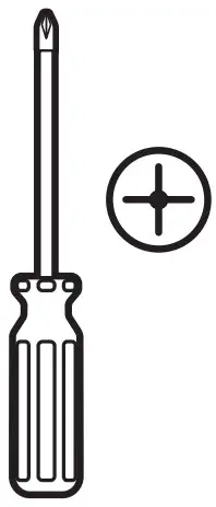
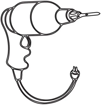
TOOLS REQUIRED
- Phillips screwdriver

- Power Drill

PACKAGE CONTENTS
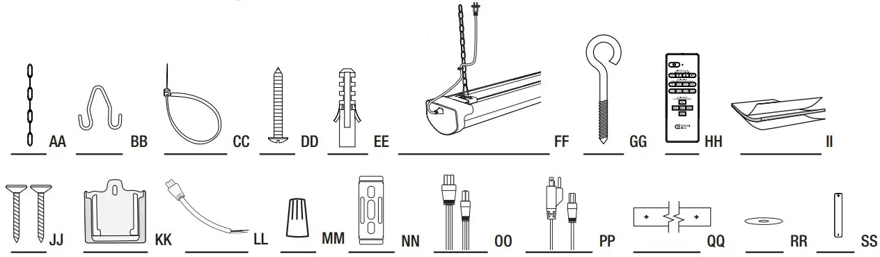
| Part | Description | Quantity |
| AA | 6 in. Hanging Chain | 2 |
| BB | V-Hook | 2 |
| CC | Zip Tie | 3 |
| DD | Mounting Screw | 4 |
| EE | Wall Anchor | 4 |
| FF | Utility Fixture | 1 |
| GG | Screw Hook | 2 |
| HH | Remote | 1 |
| II | Double Sided Tape(For remote mount) | 1 |
| JJ | Screws (For remote mount) | 2 |
| KK | Remote Mount | 1 |
| LL | 6 in. Hardwire Pigtail | 1 |
| MM | Wire Nut | 3 |
| NN | C-Channel Bracket | 2 |
| OO | 5 ft. Linking Cable | 1 |
| PP | 5 ft. Power Cable | 1 |
| Mounting Template | 1 | |
| RR | Washer | 4 |
| SS | AAA Batteries | 2 |
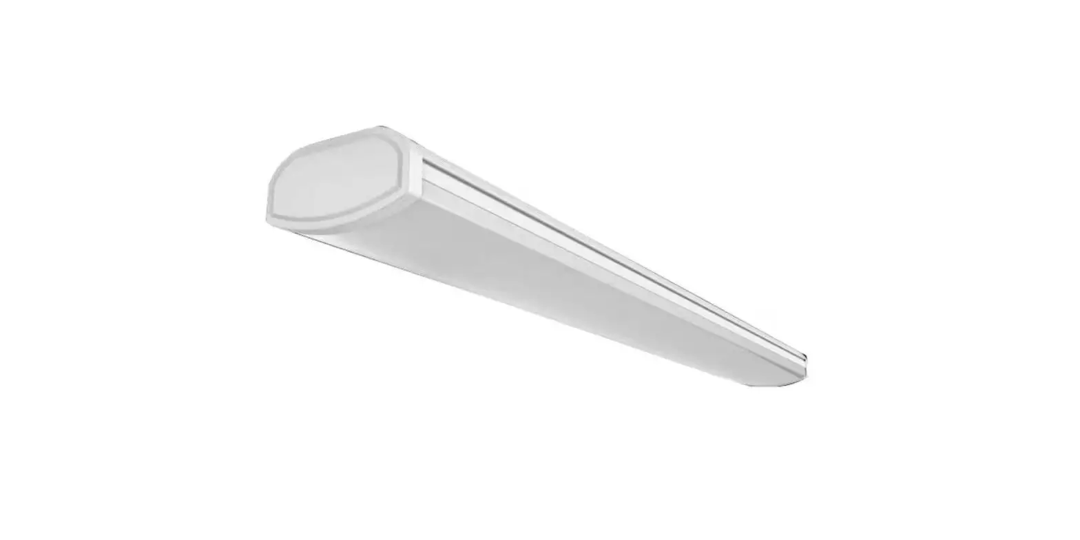
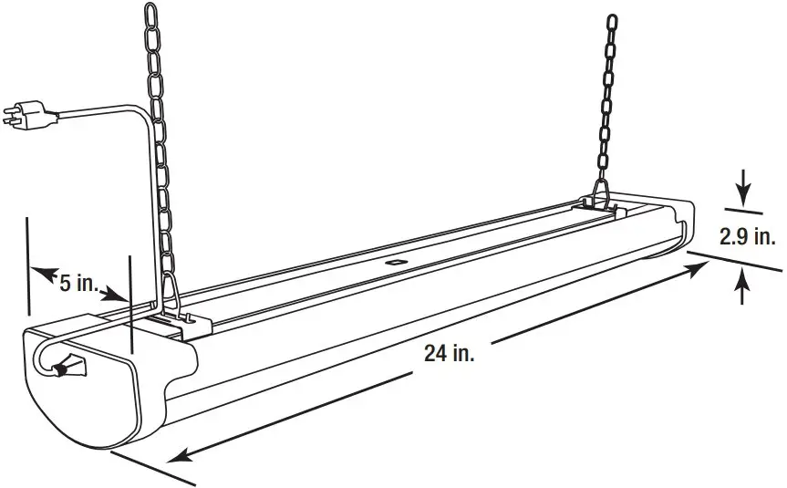
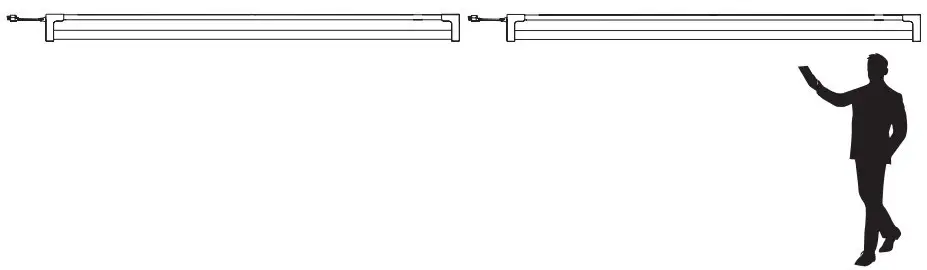
PRODUCT DIMENSIONS
Hanging Installation
Turning off the power
Turn the power OFF at the switch, fusebox, or circuit breaker. Do not plug in until complete with installation.
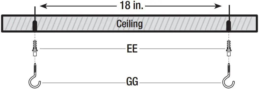
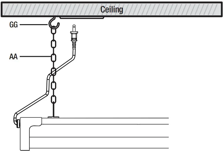
Attaching the screw hooks to a drywall ceiling
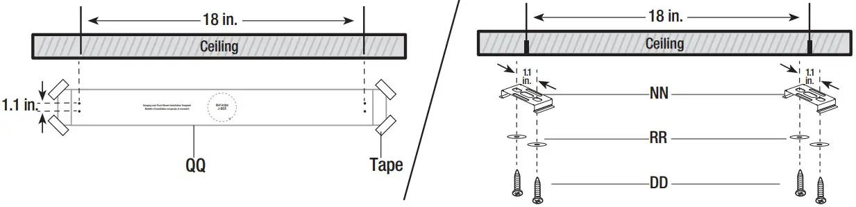
- Mark the location for the wall anchors (EE) using the mounting template (QQ). The spacing between the wall anchors (EE) should be 18 inches.
- Screw in the screw hooks (GG) into the wall anchors (EE)
- For drywalls use 7/32 drill bits.
- For wood ceilings, screw in the screw hooks (GG) directly into the wood ceiling

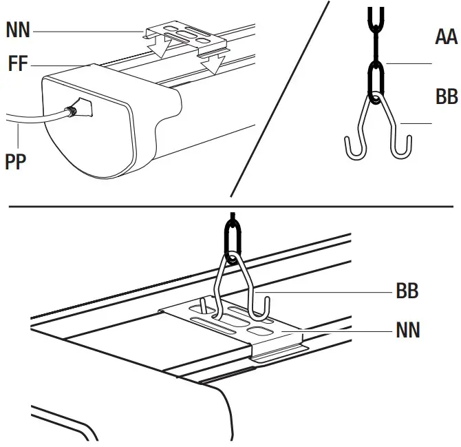
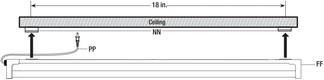
Installing the hanging chains to V-hooks
- Press down rmly on the C-channel brackets (NN) to snap into the groove on the top of the utility xture (FF). Slide the C-channel brackets (NN) about 18 inches apart.
- Place the V-hook (BB) through the bottom rung of the hanging chain (AA).
- Squeeze on the V-hook (BB) and insert it through the center of the C-channel bracket (NN).
- Plug power cord (PP) into xture (FF).

Attaching the hanging chains
- Hang the hanging chains (AA) onto the screw hooks (GG) and plug in the power cord to the outlet.

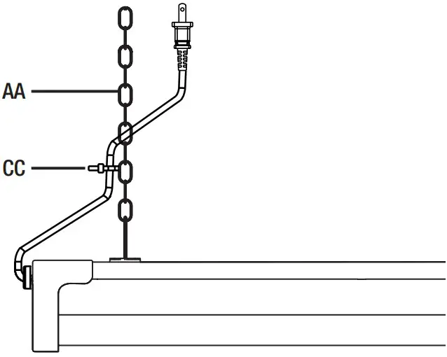
Attaching the zip tie
- Use the zip tie (CC) to attach the cord to the hanging chain (AA).

Turning on the power
- Turn the xture ON/OFF using the provided remote.
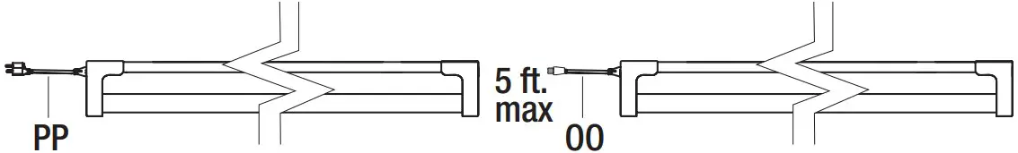
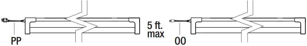
Linking multiple fixtures (optional)
- Link up to 6 with included linking cable (OO) Maximum distance between shoplights is 5 feet

Flush Mount Plug-In Installation
Turning off the power
Turn the power OFF at the switch, fusebox, or circuit breaker. Do not plug in until complete with installation.
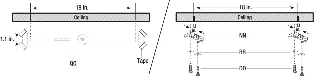
Attaching the mounting screws and C-channel brackets
- Position the mounting template (QQ) in the desired xture location on the ceiling. Mark the location for the mounting screws (DD) using the mounting template (QQ). The spacing between the mounting screws (DD) should be 1.1 inches and 18 inches apart.
- Use the washers (RR) and mounting screws (DD) to mount the C-channel brackets (NN) to the ceiling. Use included wall anchors and a 7/32 drill bit if ceiling is drywall or concrete.

Securing the fixture
- Lift the utility xture (FF) up to the to the C-channel brackets (NN). Push rmly until the C-channel brackets (NN) snap into the lenghtwise groove on the top of the utility xture (FF). Plug power cord (PP) into xture (FF) and to the outlet.

Turning on the power
- Turn the xture ON/OFF using the provided remote.
Linking multiple fixtures (optional)
- Link up to 6 with included linking cable (OO)
- Maximum distance between shoplights is 5 feet.

 Connect to power outlet Connect to additional shoplight Maximum Distance 5ft
Flush Mount Hardwire Installation
Turning off the power
Turn the power OFF at the switch, fusebox, or circuit breaker. Do not plug in until complete with installation.
Attaching the mounting screws and C-channel brackets
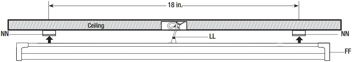
- Position the mounting template (QQ) in the desired xture location on the ceiling. Mark the location for the mounting screws (DD) using the mounting template (QQ). The spacing between the mounting screws (DD) should be 1.1 inches and 18 inches apart.
- Use the washers (RR) and mounting screws (DD) to mount the C-channel brackets (NN) to the ceiling. Use included wall anchors and a 7/32 drill bit if ceiling is drywall or concrete.

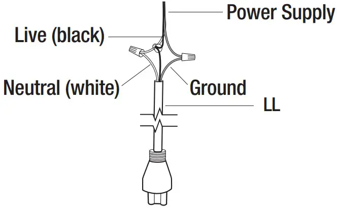
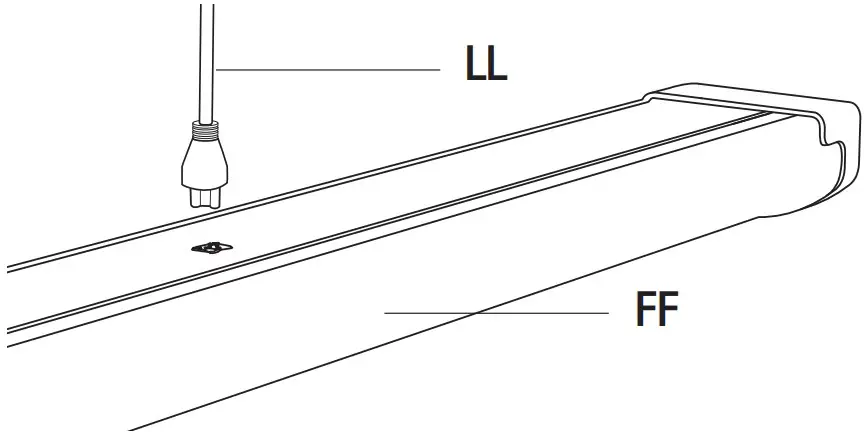
Wiring power supply to the fixture
- Connect supply wires to the 6 inch hardwire pigtail (LL).
Connect the 120V live (black) wire to the black wire.
Connect the neutral (white) wire to the white wire.
Connect the ground wire to the ground wire.
Plugging the pigtail into the fixture
- Plug the hardwire pigtail (LL) into the socket on top of the xture (FF).

Securing the fixture
- Lift the utility xture (FF) up to the to the C-channel brackets (NN). Push rmly until the C-channel brackets (NN) snap into the groove on the top of the utility xture (FF).
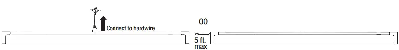
 Connect to additional shoplight Maximum Distance 5ft.
Linking multiple fixtures (optional)
- Linking multiple xture ush mounted using a single junction box (optional).
- Link up to six with included linking cable. Maximum distance between shoplights is 5 feet

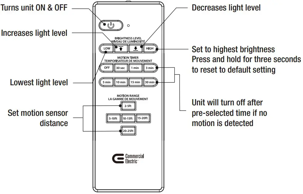
Using the IR Remote
Remove the back cover to replace the batteries.
Follow the correct polarity.
Remote only uses (2) AAA batteries.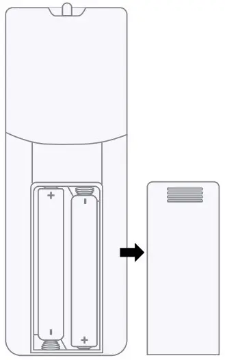
![]() NOTE:
NOTE:
- Do not mix old and new batteries
- Do not mix alkaline, standard (carbon-zinc), or rechargeable (ni-cad, ni-mh, etc) batteries.
IMPORTANT: Dispose of used (or excess) batteries in compliance with federal, state/provincial and local regulations. Do not accumulate large quantities of used batteries for disposal as accumulations could cause batteries to short‐ circuit. Do not incinerate. Do not dispose of batteries in household trash.
Group Programing
Programming multiple fixtures
- Press down and hold the desired brightness light setting (HIGH or LOW). While holding the desired light setting, walk closer towards the fixture until it flashes. The flashing is an indicator that the desired light setting was recorded.
- While holding down the desired light setting, continue walking towards each individual fixture that you intend to link. When the fixture flashes, you have linked successfully (can link up to six)

- Maximum distance between shoplights is 5 feet.
![]() NOTE: If the fixture did not flash, it did not receive the new light setting.
NOTE: If the fixture did not flash, it did not receive the new light setting.
![]() NOTE: Fixture uses motion sensors which could interfere with WiFi within 5 ft of the unit.
NOTE: Fixture uses motion sensors which could interfere with WiFi within 5 ft of the unit.
Motion Sensor
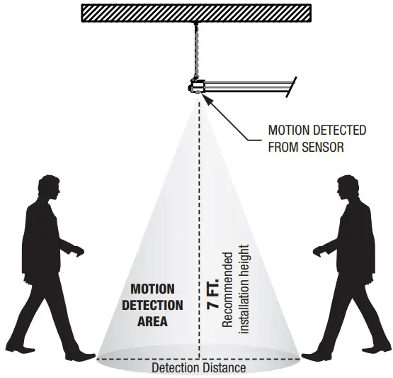
Approximate radius determined by remote control.
![]() NOTE: All distances are measured from motion sensor not from the fixture.
NOTE: All distances are measured from motion sensor not from the fixture.
![]() NOTE: Motion detection works best when walking across the sensor at an angle.
NOTE: Motion detection works best when walking across the sensor at an angle.
![]() NOTE: Recommended installation height is 7ft.
NOTE: Recommended installation height is 7ft.
SENSOR DETECTION
Can be adjusted from 2 to 25 feet using the remote control.
Troubleshooting
| Problem | Cause | Solution |
| Light is not coming out of fixture | Light is not plugged in or is turned off | Plug in and turn on using remote |
| Fixture does not react to remote | Batteries are dead | Replace dead batteries with new AAA batteries |
| Batteries are inserted incorrectly | Ensure batteries are in the correct orientation | |
| Remote is out of range | Move closer to fixture | |
| Light turns on without discernible movement | Motion detector triggered | Use remote to select a smaller detection radius (microwave motion detectors can trigger through walls and doors) |
| Light stays off despite movement | Detection radius too small | Use remote to select a larger detection radius |
| Light does not go off | Motion detector is being constantly triggered | Use remote to select a smaller detection radius (microwave motion detectors can trigger through walls and doors) |
| Motion detection setting is turned off | Use remote to select a motion detection time frame under the label “MOTION TIMER” | |
| Light loses functionality when linked to another light | Faulty cable connection | Ensure cable connections are sound and try again |
| Sensor interference | Ensure fixtures are more than 3ft apart from each other |
FCC STATEMENT
This device complies with part 15 of the FCC Rules. Operation is subject to the following two conditions:
(1) This device may not cause harmful interference, and (2) this device must accept any interference received, including interference that may cause undesired operation. Note: This equipment has been tested and found to comply with the limits for a Class B digital device, pursuant to part 15 of the FCC Rules. These limits are designed to provide reasonable protection against harmful interference in a residential installation. This equipment generates, uses and can radiate radio frequency energy and, if not installed and used in accordance with the instructions, may cause harmful interference to radio communications. However, there is no guarantee that interference will not occur in a particular installation. If this equipment does cause harmful interference to radio or television reception, which can be determined by turning the equipment off and on, the user is encouraged to try to correct the interference by one or more of the following measures: Reorient or relocate the receiving antenna. Increase the separation between the equipment and receiver. Connect the equipment into an outlet on a circuit different from that to which the receiver is connected. Consult the dealer or an experienced radio/TV technician for help. Any changes or modifications not expressly approved by the manufacturer could void the user’s authority to operate the equipment. CAN ICES-005 (B) / NMB-005 (B).
Supplier’s Declaration of Conformity:
47 CFR § 2.1077 Compliance Information
Responsible Party:
Feit Electric Company
4901 Gregg Road,
Pico Rivera, CA 90660, USA
562-463-2852
Unique Identifier:
WRAP2C840IRMM/HD/CAN
ISED STATEMENT
This device complies with Industry Canada’s licence-exempt RSSs.
Operation is subject to the following two conditions: (1) This device may not cause interference; and (2) This device must accept any interference, including interference that may cause undesired operation of the device.
Limited Warranty
This product is warranted to be free from defects in workmanship and materials for up to 5 years from date of purchase. If it fails to do so, please contact the Customer Service Team at 1-877-527-0313 or visit www.homedepot.ca.
Questions, problems, missing parts? Before returning to the store, call Commercial Electric Customer Service 8 a.m. – 7 p.m., EST, Monday – Friday, 9 a.m. – 6 p.m., EST, Saturday 1-877-527-0313 HOMEDEPOT.CA
Retain this manual for future use.


 Led Light Strip With Ir Remote Control User Manual")