![]()
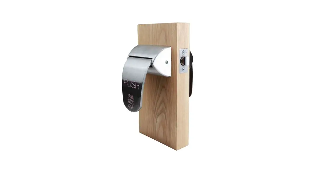
LR6000Q – QUIET (CYLINDRICAL LATCH)
INSTALLATION INSTRUCTIONS
LR6000Q Ligature-Resistant Cylindrical Latches
NOTES
- TRIM CAN BE MOUNTED UP, DOWN, VERTICALLY. **
- USES STANDARD 161 DOOR PREP.
- VISION LITE MUST BE AT LEAST 6″ FROM CENTERLINE OF TRIM.

PARTS LIST ITEM QTY DESCRIPTION 1 2 ADAPTER PLATE 2 4 TORSION SPRING 3 1 LATCH 4 4 12-24 X 3/8″ FHMS 5 4 12-24 NUT W/ NYLON WASHER 6 2 COVER 7 2 HANDLE 8 2 ADJUSTABLE ADAPTER PLATE 9 2 CAM HOLDER 10 2 CAM 11 2 BASE, WIDE HANDLE, LOW PROFILE 12 2 HANDLE, PUSH/PULL, LP BACKSET 13 4 12-24 X 1/2″ FHMS 14 4 12-24 x 2-3/8″ PH. TRUSS HD. M.S. 15 8 8-32 X 3/8″ FHMS 16 2 #8 x 3/4″ FHWS OR #8-32 X 3/8″ FHMS 17 4 10-32 X 1/2″ PFHMS 18 4 8-32 X 3/8″ OVAL HEAD M.S.
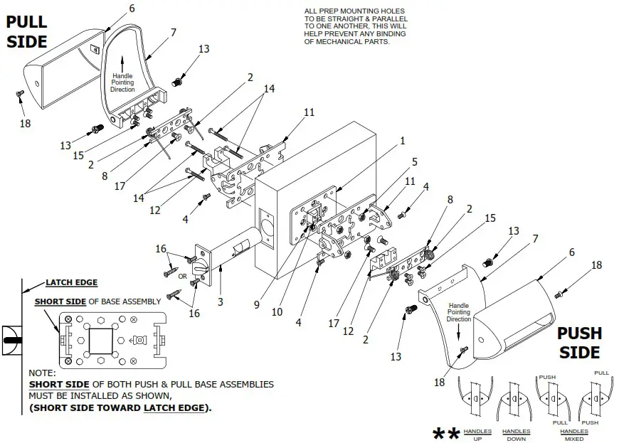
INSTALLATION INSTRUCTIONS:
Base assemblies come pre-assembled – above drawing shows blown-up view for reference.
- Prep door according to LR6000Q Series latch template.
- Install latch using either #8 wood screws or 8-32 machine screws (Item 16).
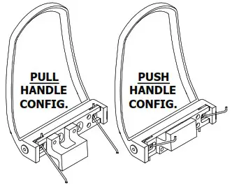
- Unscrew the (4) 10-32 screws (Item 14) that are fastened with Keps Nuts (Item 5) on the pre-assembled pull side trim and set aside. Locate and install pull base assembly on pull side of door with SHORT SIDE toward the lock edge of the door as shown above.
- Install the push base assembly onto the push side of the door by inserting the (4) 10-32 screws (Item 14) thru the pull base assembly. Fasten with the Keps Nuts (Item 5) on the push side of the door.
- Install the push handle assembly (Item 7) to the base assembly installed on push side of door using (2) phillips head cap screws (Item 13). Install (2) stop screws (Item 4) through the push base assembly on each side. Test push handle for proper operation to be sure stop screws were installed in the appropriate base assembly holes.
- Place covers (Item 6) over handles and fasten each cover with (2) 8-32 screws (Item 18).
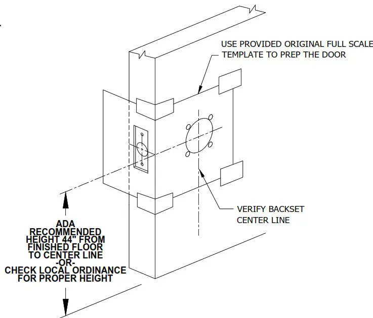
LR6000Q PUSH/PULL LATCH – DOOR PREP
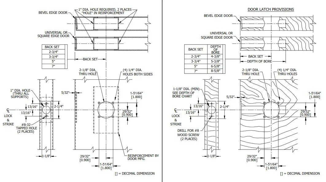
METAL DOOR
DOOR PREP INFORMATION:
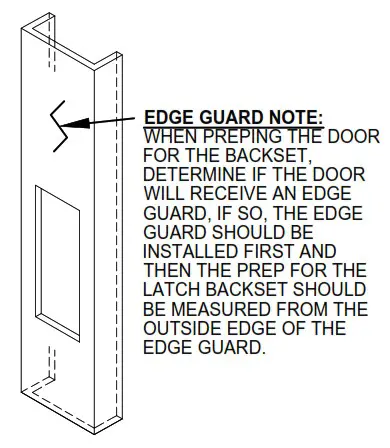
- BACKSET DIMENSION FROM LOW EDGE OF BEVEL.
- CENTER PUNCH ALL HOLES.
- DRILL HOLES (FOR HOLLOW METAL DOORS,
DO NOT DRILL THRU. CENTER PUNCH & DRILL
HOLES FROM BOTH SIDES OF DOOR).
WOOD DOOR
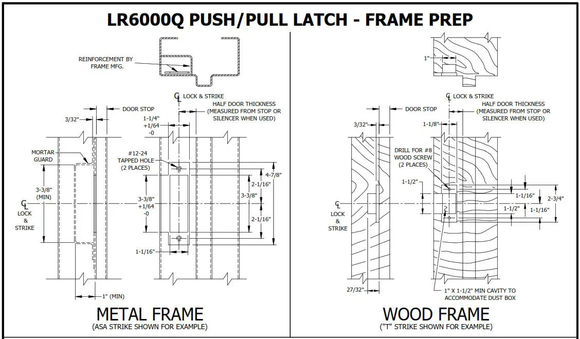
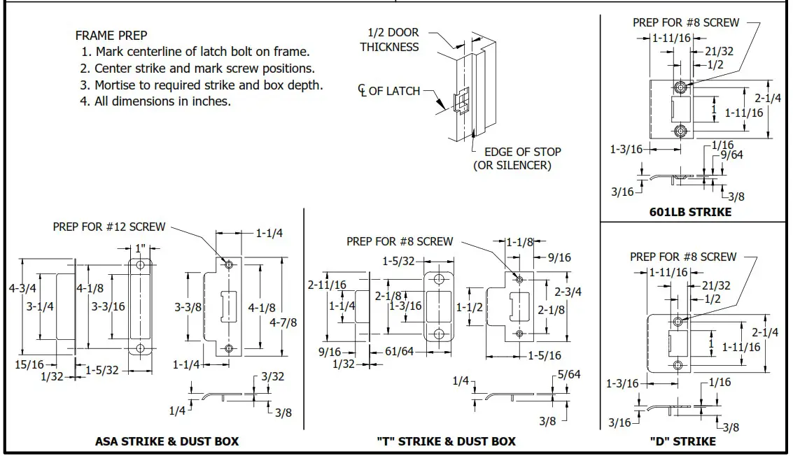
LR6000Q PUSH/PULL LATCH – FRAME PREP
LR6000Q PUSH/PULL LATCH – HANDING CHANGE
REFERENCE PAGE 1 FOR PARTS LIST & EXPLODED VIEW PULL SIDE HANDLE
- Remove cover (Item 6) by unscrewing the (2) 8-32×3/8″ (Item 15)screws.
- Unscrew the 12-24 x 3/8″ screws (Item 4) from each side of the base (Item11).
(Note its location on the handle/base assembly) - Remove 12-24 x 1/2″ phillips head cap screw (Item 13) from one side of the handle (Item 7).
- Remove the (2) 10-32×1/2″ Phillips flat head screws (item 17) from the adjustable adapter plate (Item 8).
(Note the springs (location on the handle).
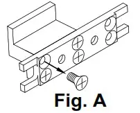
- Remove the (4) 8-32×3/8″ Phillips flat head screws (Item 15) that hold the LP bracket (Item 12) to the adjustable adapter plate (item 8) see Fig. A.

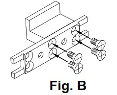
- Slide the LP Backset (Item 12) over to the other side of the adjustable adapter plate (item 8) and reassemble with the same screws see Fig. B. (Keep the LP Backset orientation the same)

- Repeat the same process 1 thru 6 for the PUSH SIDE HANDLE.
- Remove the (4) 10-32×2-1/2″ RHMS (Item 14) that hold base assembly/adapter plate (Item 11&1) to the door.
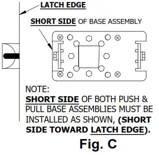
(Note the orientation of the base assembly on the door this will go back on the same way it came off see Fig. C)
- Remove the (2) #8 screws (Item 16) that hold the latch bolt(Item 3).
- Rotate the latch bolt (item 3) 180° and return the (2) #8 screws (item 16). (Flip the handles & base assemblies to their perspective sides, keeping the SHORT SIDE of both PULL & PUSH base assemblies toward LATCH EDGE of the door, see Fig. C).
- Reinstall the (4) 10-32×2-1/2″ RHMS (item 14) that hold base/adapter assemblies (Item 11&1) to the door.
- Reinstall the Pull Handle (item 8) using the phillips head cap screw (Item 13) that was removed. (Make sure both springs are pointing in the proper direction on the base assembly).
- Reinstall the 12-24 x 3/8″ screws (Item 4) in its proper location on the base assembly (Item 11).
- Reinstall the Push Handle (item 8) using the phillips head cap screw (item 13) that was removed. (Make sure both springs are pointing in the proper direction on the base assembly).
- Reinstall the 12-24 x 3/8″ screws (Item 4) in its proper location on the base assembly (Item 11).
- Reinstall cover (Item 6) by using the (2) 8-32×3/8″ (Item 16) screws.
![]()
www.abhmfg.com
E-mail: [email protected]
ArchteicturaBl udliersHardwareMfg.,Inc.
1222ArdmoreAveatI,.scaLI,60143
6308.759.900F;AX8009.FAXABH(9329.224)
©2021ABH Mfg Inc.
pneirtnd in USA
LR6000Q REVISED 12-17-21


