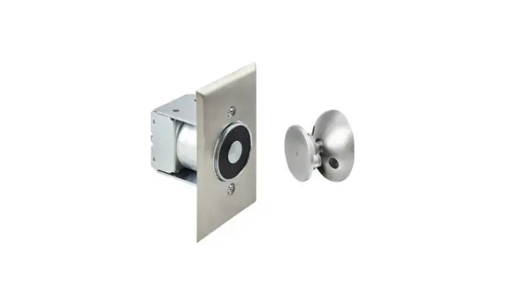
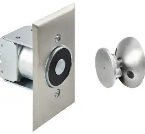
ABH 2300 C28 Surface Mount Magnetic Door Holder
WALL PORTION INSTALLATION:
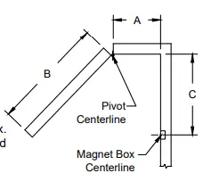
- Measure distance from pivot centerline to wall (Dim. “A”).
- Determine door width (Dim. “B”).
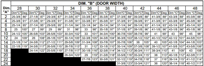
- Use table below to locate magnet box on wall (Dim. “C”).
- Example : Dim. “A” = 10″ Dim. “B” = 42″ Result Dim. “C” = 38-7/8″.
- If Dim. “A” or Dim. “B” falls between dimensions listed in the table below, allow for difference.
- Example : Dim. “A”= 7” Dim. “B” = 36″ Then Dim.”C” = 33-1/8″.

- If Dim. “A” and Dim. “B” intersect in the shaded area, DO NOT INSTALL magnet box.
- The degree of door opening will not allow for proper alignment between armature and wall magnet.
- Suggested vertical location is on top rail approximately 5″ from top of the door.
- Check degree of door opening shown in table and coordinate with door closer and other door hardware.
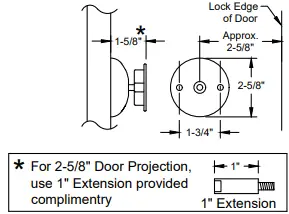
- Total projection of door hardware must not be more than 3-5/8″ on the pull side of door.
- If greater, you will need to use additional extensions, sold separately.
- From corner of wall, measure the appropriate Dim. “C” determined in step 3.
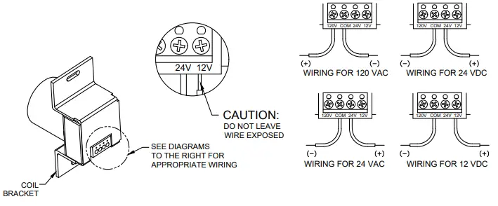
- Proper electrical wire routing must be done before installing magnet box.
- The 4″ x 2-1/8″ x 2″ outlet box (not provided with unit) should be installed with reinforcement to withstand a minimum 50 lb. pull.

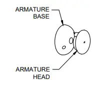
DOOR ARMATURE ASSEMBLY
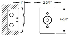
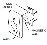
2100 MAGNETIC WALL PORTION
VIEW
TOP VIEW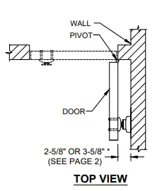
FRONT VIEW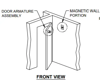
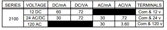
ELECTRICAL DATA
DOOR ARMATURE INSTALLATION
- Place and center the door armature on the surface of the magnet with the two holes of the base aligned horizontally.
- Gently close the door and adjust the angle of the door armature so the base lays flat against the door.
- While keeping slight pressure on the door, mark location of door armature through the two base holes.
- Drill through the door where the two marks are located with 5/16″ drill.
- Fasten with the (2)10-32 machine screws & sex bolts provided.

HELP
- www.abhmfg.com
- E-mail: [email protected]
- Architectural Builders Hardware Mfg., Inc.
- 1222 Ardmore Ave., Itasca, IL 60143
- 630.875.9900; FAX 800.9FAXABH (932.9224)


