![]() Operating and installation instructions
Operating and installation instructions
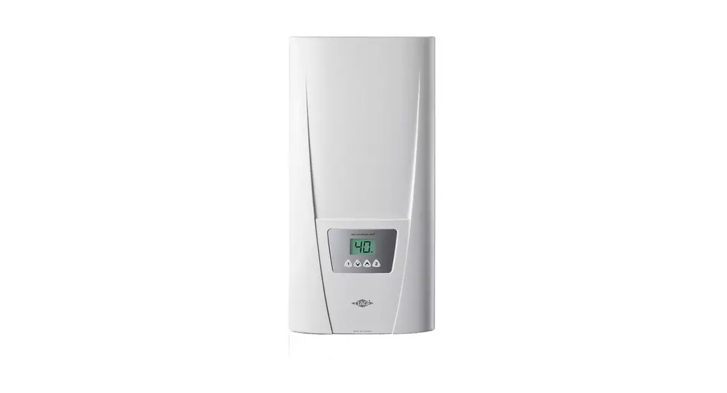
E-convenience instant water heater DLX Next![]()
DLX Next
The documents supplied with the device must be stored carefully.
Registration
Register your device online on our website and benefit from our services under warranty.
Your full details help our customer service process your request as fast as possible.
For online registration, just follow the link below or use the QR code with your smartphone or tablet.
https://partner.clage.com/en/service/device-registration/
 https://partner.clage.com/en/service/device-registration/index.php
Operation instruction
Note: Carefully read the enclosed safety instructions through in full before the appliance is installed, put into service and used and follow them in the further steps and during use!
Description of the appliance
 The E-convenience instant water heater DLX Next is a electronically controlled pressure-resistant instantaneous water heater for an efficient water supply to one or more tap outlets.
Its electronic control regulates the power consumption depending on the selected outlet temperature, the respective inlet temperature and the flow rate, thus reaching the set temperature exactly to the degree and keeping it constant in case of water pressure fluctuations. The outlet temperature can be set to 35 °C, 45 °C or 55 °C using the central sensor key.
In case of a low feed temperature and a high flow rate at the same time, it could happen that the preset outlet temperature is not reached which is due to the fact that the appliance exceeded its capacity.
The outlet temperature can be raised by reducing the water flow at the tap.
It is possible to use the instantaneous water heater in combination with an external load shedding relay for electronically controlled instantaneous water heaters (refer to installing instructions).
As soon as you open the hot water tap, the instantaneous water heater switches on auto ma ti cally. When the tap is closed, the appliance automatically switches off.
Environment and recycling
![]() This product was manufactured climate neutrally according to Scope 1 + 2. We recommend the purchase of 100% green electricity to make the operation climate neutral as well.
This product was manufactured climate neutrally according to Scope 1 + 2. We recommend the purchase of 100% green electricity to make the operation climate neutral as well.
Disposal of transport and packaging material: For smooth transport your product is carefully packed.
The disposal of the transport material is carried out by the specialist tradesman or the specialist trade. Separate the sales packaging according to materials separated according to materials via one of the dual systems in Germany.
Disposal of old products: Your product was manufactured from high-quality, reusable materials and components.
Products marked with the crossed-out wheeled bin symbol must be disposed of separately from household waste at the end of their service life.
Therefore, take this product to us as the manufacturer or to one of the municipal collection points that recycle used electronic devices.
This proper disposal serves to protect the environment and prevents possible harmful effects on humans and the environment that could result from improper handling of the products at the end of their service life. For more detailed information on disposal, please contact your nearest collection point or recycling centre or your local council.
Business customers: If you wish to discard equipment, please contact your dealer or supplier for further information.
For disposal outside Germany, please also observe the local regulations and laws.
How to use
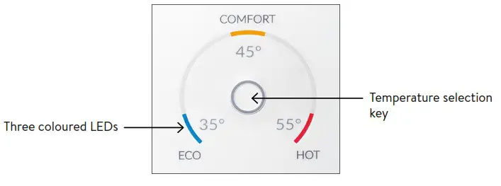
Temperature setting
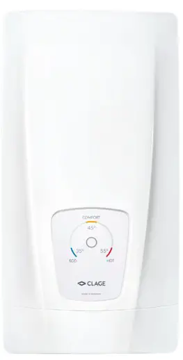
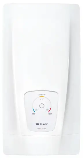
The temperature selection key![]() allows you to quickly select one of three preset temperatures, that are typical for hot water applications: “Hand wash” 35 °C, “Bath tub” 45 °C and “Cleaning” 55 °C.
allows you to quickly select one of three preset temperatures, that are typical for hot water applications: “Hand wash” 35 °C, “Bath tub” 45 °C and “Cleaning” 55 °C.
Every key press sets the temperature to the next level: 35 °C![]() 45 °C
45 °C ![]() 55 °C
55 °C
Pressing the key ![]() once again, starts the cycle all over.
once again, starts the cycle all over.
The currently selected temperature is indicated by one of three coloured LEDs.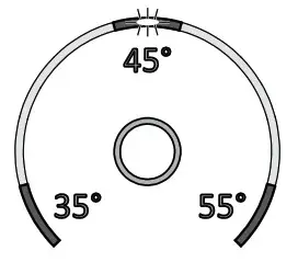 Power limit
If the full output of the instantaneous water heater DLX Next does not suffice to heat the tapped quantity of water, this will be indicated by flashing of the temperature LED (e.g. in winter time, when open ing several taps at once). When you reduce the hot
water flow rate, the LED lights up continuously again because the output of the appliance is again sufficient to reach the set temperature.
Device information
Press and hold the temperature selection key for 10 seconds to open the info mode.
After ten seconds, all LEDs light up once briefly and then switch off again immediately to confirm that the info mode is active.
The device status is displayed via the LEDs:
LED bottom left: OFF = no water flow; FLASHING = water flow below switch-on point; ON = water flow above switch-on point.
LED top middle: ON = heating active; FLASHING = power limit. Otherwise OFF.
LED bottom right: OFF = device OK; FLASHING = error detected (inform customer service)
The display returns to normal operation after 60 seconds or after a key press.
Venting after maintenance work![]() This instantaneous water heater features an automatic air bubble protection to prevent it from inadvertently running dry. Nevertheless, the appliance must be vented before using it for the first time. Each time the appliance is emptied (e.g. after work on the plumbing system, if there is a risk of frost or following repair work), the appliance must be re-vented before it is used again.
This instantaneous water heater features an automatic air bubble protection to prevent it from inadvertently running dry. Nevertheless, the appliance must be vented before using it for the first time. Each time the appliance is emptied (e.g. after work on the plumbing system, if there is a risk of frost or following repair work), the appliance must be re-vented before it is used again.
 Disconnect the instantaneous water heater from the mains (e.g. via deactivating the fuses).
- Unscrew the jet regulator on the outlet fitting and open the cold water tap valve to rinse out the water pipe and avoid contaminating the appliance or the jet regulator.
- Open and close the hot water tap until no more air emerges from the pipe and all air has been eliminated from the water heater.
- Only then should you re-connect the power supply again (e.g. via activating the fuses) to the instantaneous water heater and screw the jet regulator back in.
- The appliance activates the heater after approx. 10 seconds of continuous water flow.
Cleaning and maintenance
- Plastic surfaces and fittings should only be wiped with a damp cloth. Do not use abrasive or chlorine-based cleaning agents or solvents.
- For a good water supply, the outlet fittings (e.g. jet regulators and shower heads) should be unscrewed and cleaned at regular intervals. Every three years, the electrical and plumbing components should be inspected by an authorised professional in order to ensure proper functioning and operational safety at all times.
Trouble-shooting and service
![]() Repairs must only be carried out by authorised professionals.
Repairs must only be carried out by authorised professionals.
If a fault in your appliance cannot be rectified with the aid of this table, please contact the service organisation of your importer or the Central CustomerService Department. Please have the details of the typeplate at hand.
CLAGE GmbH
After-Sales Service
Pirolweg 4
21337 Lüneburg
Germany
Phone: +49 4131 8901-400
Email: [email protected]
This instantaneous water heater was manufactured conscientiously and checked several times before delivery.
Should malfunctions nevertheless occur, it is usually only due to a bagatelle. First attempt to switch the house fuses off and on again in order to reset the electronics.
Next, try to remedy the problem with reference to the following table.
In doing so, you will avoid unnecessary expense of customer service assistance.
| DLX Next | ||
| Problem | Cause | Solution |
| Water stays cold, tempera- ture LED does not light up | Master fuse tripped | Renew or activate fuse |
| Safety pressure cut-out tripped | Contact customer service | |
| Water stays cold, tempera- ture LED does light up | Safety thermal cut-out tripped | Contact customer service |
| Water stays cold, all LEDs flash | Internal error | Contact customer service |
| Water heats up, all LEDs flash with exception of the tern- perature indication | Appliance detected an error | Contact customer service |
| Flow rate of hot water too weak | Outlet fitting dirty or calci- fled | Clean shower head, jet regulator or sieves |
| Fine filter dirty or calcified | Let clean fine filter by customer service | |
| Temperature indication LED flashes | Power limit reached | Decrease the warm water flow at the tap |
| Selected temperature is not reached | Cold water has been added via the tap | Tap hot water only; set tempera-ture, check outlet temperature |
| Sensor key does not respond correctly or only sporadically | Display is wet | Dry display by wiping it with a soft cloth |
Product data sheet in accordance with EU regulation – 812/2013 814/2013
| a | b | c | d | e | f | h | i | |
| b.1 | b.2 | 11WH | AEC | °C | LWA | |||
| % | kWh | dB(A) | ||||||
| CLAGE | DLX18 Next | 5E-180W-3C | XS | A | 39 | 470 | 55 | 15 |
| CLAGE | DLX 21 Next | 5E-210W-3C | XS | A | 39 | 470 | 55 | 15 |
| CLAGE | DLX 24 Next | 5E-240W-3C | XS | A | 39 | 470 | 55 | 15 |
Explanations
| a | Brand name or trademark |
| b.1 | Model |
| b.2 | Type |
| c | Specified load profile |
| d | Energy-efficiency class |
| e | Energy-efficiency |
| f | Annual power consumption |
| g | Additional load profile, the appropriate energy-efficiency and the annual power consumption, if applicable |
| h | Temperature setting for the temperature controller |
| i | Sound power level, internal |
Additional notes
| All specific precautions for assembly, installation, maintenance and use are described in the operating and installation instructions. | |
| All data in this product data sheet are determined by applying the specifications of the relevant European directives. Differences to other product information listedelsewhere may result indifferent test conditions. | |
| The power consumption was determined in compliance with standardized measurement method based on EU guidelines. The real energy consumption is pending on individual requirements. |
Installation instruction
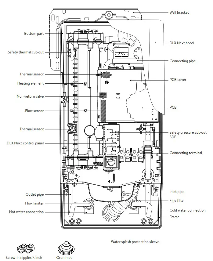
Overview
Technical specifications
| Model | DLX18 Next | DLX 21 Next | DLX 24 Next | |||
| Energy efficiency class | A *) | |||||
| Rated capacity / rated current | 18 kW / 26A | kW 16.225A / | 21kW / 30A | 19 kW / 29A | 24 kW / 35A | 21.7 kW / 33A |
| Rated voltage | 400V | 380V | 400V | 380V | 400V | 380V |
| Electrical connection | 3-/PEAC | |||||
| Min. required cable size” | 4.0 mm2 | 4.0 mm2 | 6.0 mm2 | |||
| Hot water (I/min) max. at At = 28 K max. at At = 38 K | 9.22) 6.8 | 8.32) 6.1 | 10.721 7.9 | 9.721 7.2 | 12.3 2) 9.021 | 11.12) 8.22) |
| Rated volume | 0.41 | |||||
| Rated pressure | 1.0 MPa (10 bar) | |||||
| Connecting type | pressure-resistant / pressureless | |||||
| Heating system | Bare wire heating system IESs | |||||
| @ 15 °C: Required specific water resistance Specific electrical conductivity | ?B000cm 5 90 mS/m | |||||
| Inlet temperature | 5 30 °C | |||||
| Flow rate to switch on – max. flow rate | 1.51/min – 7.0 37 | 1.51/min – 8.0 3) | 1.51/min – 8.0 3) | |||
| Pressure loss | 0.08 bar at 1.51/min 1.3 bar at 9.0 l/min 4) | |||||
| Temperature range | 35°C / 45°C / 55°C | |||||
| Water connection | G ‘A inch | |||||
| Weight (when filled with water) | 4.2 kg | |||||
| VDE class of protection | 1 | |||||
| Type of protection / safety | ||||||
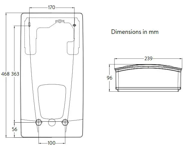
Dimensions

Installation
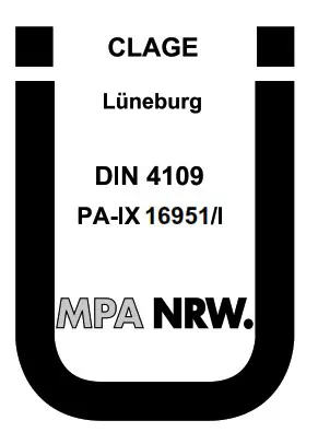
Based on the national constitution guidelines a general test certificate concerning the evidence of applicability of noise behaviour is granted.
The following regulations must be observed:
- e.g. VDE 0100
- EN 806
- Installation must comply with all statutory regulations, as well as those of the local electricity and water supply companies.
- The rating plate and technical specifications
- Only intact and appropriate tools must be used
Installation site
- Appliance must only be installed in frost-free rooms. Never expose appliance to frost.
- The Appliance must be wall mounted and has to be installed with water connectors downward or alternative transversely with water connections left.
- The appliance complies with protection type IP25 and may therefore be installed in protection zone 1 according to VDE 0100 part 701 (IEC 60364-7).
- In order to avoid thermal losses, the distance between the instantaneous water heater and the tap connection should be as small as possible.
- The appliance must be accessible for maintenance work.
- Plastic pipes may only be used if they conform to DIN 16893, Series 2.
- The specific resistance of the water must be at least 1100 Ω cm at 15 °C. The specific resistance can be asked for with your water distribution company.
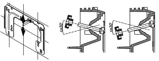
Installing the wall bracket
Note: If you install this instantaneous water heater in exchange for a conventional instantaneous water heater, there is generally no need to drill holes for the wall bracket, in this case step 2 would not be necessary.![]() Thoroughly rinse the water supply pipes before installation to remove soiling from the pipes.
Thoroughly rinse the water supply pipes before installation to remove soiling from the pipes.
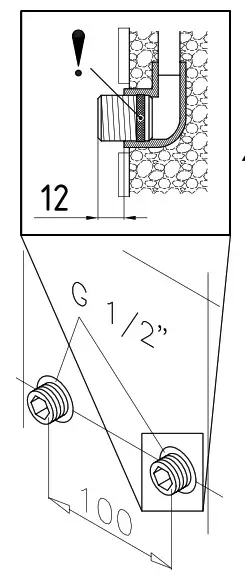
- Using a 12 mm hexagon socket screw key, screw the screw-in nipples into the wall connections. The seals must be fully screwed into the thread. After tightening, the double nipples must protrude by 12 – 14 mm.
- Hold the included mounting template on the wall and align it so that the holes in the template fit over the double nipples. Mark the drill holes according to the template and drill them using a 6 mm drill. Insert the included dowels.
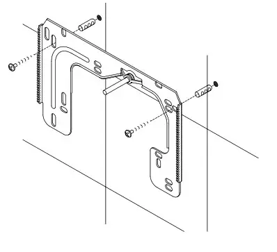
- To open the appliance pull down the faceplate and unscrew the main hood screw.
Lift the hood carefully, remove the plug from the control panel and note the position of the plug. - Loosen the knurled nut of the wall bracket, remove the wall bracket and screw it on the wall. Offset tiling or uneven surfaces can be compensated by up to 30 mm with the aid of the spacers supplied. The spacers are fitted between the wall and the wall bracket.


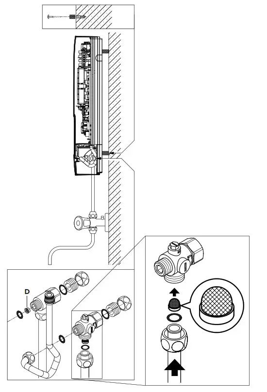
Installing connection pieces
Note: Fasten the screw nuts with caution, to avoid damage to the valves or the piping system.
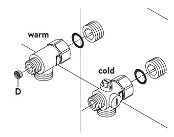
- As shown in the illustration, screw the cold water connection piece with the union nut and the ½ inch seal onto the cold water connection.
- Screw the hot water connection piece with the union nut and the ½ inch seal onto the hot water connection.
- Put the water flow limiter “D” into the hot water connection piece. The O-ring must be visible
Installing the appliance
- The electrical power supply cable may be connected in the upper part or is surface mounted. Only in such case, first follow the steps one through three according to the description “Electrical connection from above” in chapter “Electrical connection”.
1. Place the appliance on the heater bracket so that the threaded rod of the wall bracket fits in the corresponding hole of the appliance. If necessary, slight corrections are possible by carefully bending the threaded rod of the wall bracket. However, it must be possible to screw on the water connection pipes of the appliance without applyingforce.
2. Screw the plastic knurled nut onto the threaded rod of the wall bracket.
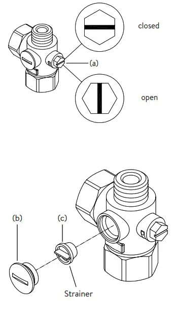
3. Screw the two ⅜ inch union nuts of the appliance‘s water connection pipes, each with the ⅜ inch seal, onto the fittings. 4. Open the water supply line to the unit and slowly open (position “open“) the shutoff valve (a) in the cold water connection piece. Check all connections for leaks.
5. Next, open and close the hot water tapping valve several times until no more air emerges from the line and all air has been eliminated from the instantaneous water heater.
 4. Open the water supply line to the unit and slowly open (position “open“) the shutoff valve (a) in the cold water connection piece. Check all connections for leaks.
Direct connection
Note: Fasten the screw nuts with caution, to avoid damage to the valves or the piping system.
For direct connection, the two ½ inch screw-in nipples and the ½ inch seals must be screwed into the ½ inch union nuts of the hot-water and cold-water connectors. The two ½ inch caps of the side outlets of the hot-water and cold-water connectors must be removed and screwed onto the open end of the screw-in nipples. Put the water flow reducer “D” into the hot water connection piece. The hot-water and cold-water connectors must then be screwed into the ⅜ inch union nut of the appliance inlet and outlet pipe, together with the ⅜ inch seals.
For direct connection, it may be advisable to mount the appliance at a distance as illustrated alongside, using the spacer sleeves supplied. The two fixing holes near the lower pipe connections are also to be professionally fixed with 6 mm dowels and screws.
The flared end of the pipes must be screwed into the ½ inch side outlets of the hotwater and cold-water connectors with ½ inch union nuts and ½ inch seals.
The holes required for the pipes must then be opened of the housing with the aid of a blunt implement.
In case of direct connection please note: Put the strainer into the cold water connection!
Electrical connection
Wiring diagram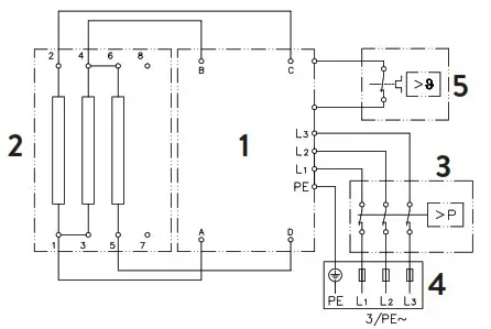
- Electronic circuitry
- Heating element
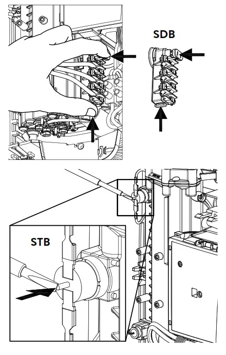
- Safety pressure cut-out
- Connecting terminal
- Safety thermal cut-out
Only by a specialist!
Please observe:
- e.g. VDE 0100
- The installation must comply with current IEC and national local regulations or any particular regulations, specified by the local electricity supply company
- The rating plate and technical specifications
- The appliance must be earthed!
Structural prerequisites
- The appliance must be installed via a permanent connection. Heater must be earthed!
- The electric wiring should not be injured. After mounting, the wiring must not be direct accessible.
- An all-pole disconnecting device (e.g. via fuses) with a contact opening width of at least 3 mm per pole should be provided at the installation end.
- To protect the appliance, a fuse element must be fitted with a tripping current commensurate with the nominal current of the appliance.
Load shedding relay
If further three-phase appliances are connected, a load shedding relay designed for electronic instantaneous water heaters (CLAGE no. 82250) can be connected to phase conductor L2.
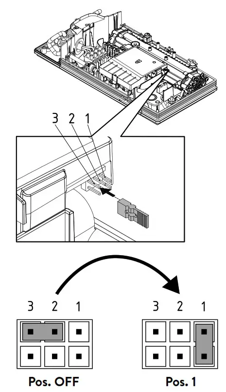
To avoid possible jitter of the load shedding relay caused by low power consumption (low temperature set point and low water flow rate) the “Load-shedding-mode” can be activated as followed:
- Disconnect the appliance from the power supply (e.g. by switching of the fuses)
- Take the jumper off the power electronics and change to position “1” (see picture).
- Put the appliance into operation again
Electrical connection from below![]() Note: If necessary, the connecting terminal can be displaced to the upper part of the appliance. If you want to do so, please follow the instructions in the next chapter.
Note: If necessary, the connecting terminal can be displaced to the upper part of the appliance. If you want to do so, please follow the instructions in the next chapter.
Check that the power supply is switched off prior to electrical connection!
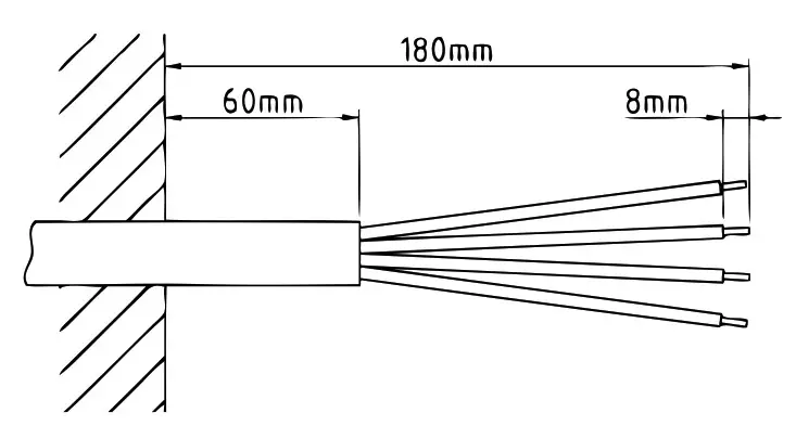
- Dismantle approximately 6 cm off the connecting cable above the wall outlet. With the smaller opening ahead, slide the water splash protection sleeve over the connecting cable so that the sleeve is flush with the wall. This prevents any leaking water from coming into contact with the electrical leads. It must not become damaged! The protection sleeve must be used!
- Strip the individual wires and plug them in the connecting terminals according to the wiring diagram. The appliance must be earthed.
- Pull the protective sleeve so far over the connecting cables and shape the connecting cables in such a way that the sleeve fits perfectly in the recess of the intermediate panel without mechanical tension and fix it with the sleeve fixing (A).
- Connect the control panel cable to the control panel in the hood, replace the hood and tighten the hood screw.
Note: The control panel cable must not be pinched or squeezed.
Electrical connection from above![]() Check that the power supply is switched off prior to electrical connection!
Check that the power supply is switched off prior to electrical connection!
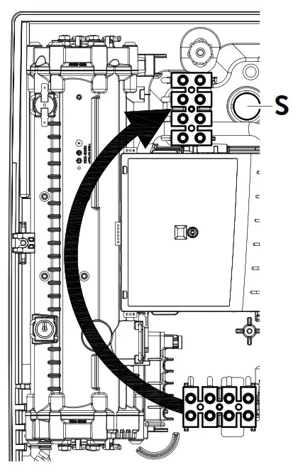
- Open the prepared breaking point (S) in the upper part of the appliance by pressing with a blunt implement (e.g. srewdriver). For surface-mounted connection cable additional open the breakout at the right side of the bottom part.
- Slit the grommet of the accessory set to match the cable size. The opening in the grommet should be slightly smaller than the cross-section of the cable in order to ensure optimum protection against water. Fit the grommet into the opening. The protection grommet must be used!
- Strip the connection cable so that the sheath extends through the grommet into the appliance. Hold the prepared appliance so that you can route the cable into the grommet with the other hand.
- Place the appliance on the wall bracket so that the threaded rod of the wall bracket fits in the corresponding hole of the appliance and fix it with the knurled nut.
- Unscrew the fastening screw of the connecting terminal. Displace the connecting terminal to the upper foot. Affix the connecting terminal again.
- Strip the individual wires of the connecting cable and plug them in the connecting terminals according to the wiring diagram. The appliance must be earthed.
- Connect the control panel cable to the control panel in the hood, replace the hood and tighten the hood screw.
Note: The control panel cable must not be pinched or squeezed.
Note: To ensure IP25 protection class, please don´t remove the bottom water splash protection sleeve.
Initial operation
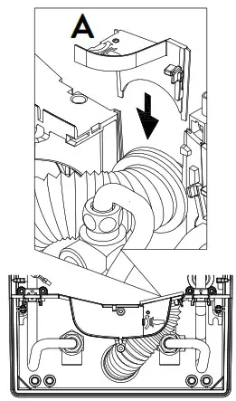
![]() Before making the electrical connection, fill the mains and the appliance with water by carefully opening and closing the hot water tap in order to vent completely.
Before making the electrical connection, fill the mains and the appliance with water by carefully opening and closing the hot water tap in order to vent completely.
To ensure a maximum flow, remove any existing aerator from the faucet. Flush the warm and cold water pipes each at least for one minute.
After every draining (e.g. after work on the plumbing system or following repairs to the appliance), the heater must be re-vented in this way before starting it up again.
If the water heater cannot be put into operation, the temperature cut-out or the pressure cut-out may have tripped during transport.
If necessary, check that the power supply isswitched off and reset the cut-out.
- Switch on the power supply to the appliance.
- Open the hot water tap. Check the function of the appliance. The heating element will be activated after approx. 10 – 30 sec of continuous water flow.
- Explain the user how the instantaneous water heater works and hand over the operating instructions.
- Fill in the guarantee registration card and send it to the CLAGE Central Customer Service or use the online registration (see also page 17).
Maintenance work
Maintenance work must only be conducted by an authorised professional.
Cleaning and replacing the filter strainer
The cold water connection of this instantaneous water heater is equipped with an integrated shut-off valve and a strainer. Soiling of the strainer may reduce the warm water output. Cleanor replace thestrainer as follows:
- De-energize the instantaneous water heater (e.g. via deactivating the fuses) and prevent inadvertent reactivation of them.
- To open the appliance, pull down the faceplate and unscrew the main hood screw. Lift the hood carefully, remove the plug from the control panel and note the position of the plug.
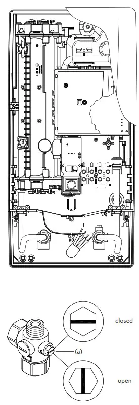
- Close the shut-off valve (a) in the cold water connection piece (position “closed“).
- Unscrew the screw plug (b) from the cold water connection piece and take out the strainer (c).
Note: Residual water can leak - The strainer can now be cleaned or re placed.
- After fitting of the clean strainer tighten the screw plug.
- Slowly reopen the shut-off valve in the cold water connection piece (posi- tion “open“). Ensure that there are no leakages.
- Vent the appliance by carefully opening and closing the affiliated warm water tap valve several times until air no longer emerges from the pipe.
- Connect the control panel cable to the control panel in the hood, replace the hood and tighten the hood screw.
Note: The control panel cable must not be pinched or squeezed. Then switch on the power again (e.g. via activating the fuses).
 De-energize the instantaneous water heater (e.g. via deactivating the fuses) and prevent inadvertent reactivation of them.
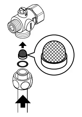
Cleaning and replacing the filter strainer if direct connected
The cold water connection of this instantaneous water heater is equipped with a strainer. Soiling of the strainer may reduce the warm water output. Clean or replace the strainer as follows:
- De-energize the instantaneous water heater (e.g. via deactivating the fuses) and prevent inadvertent reactivation of them.
- Close the shut-off valve in the mains water supply of the instantaneous water heater.
- To open the appliance, pull down the faceplate and unscrew the main hood screw. Lift the hood carefully, remove the plug from the control panel and note the position of the plug.
- Unscrew mains water inlet from connection piece and take out the strainer. Note: Residual water can leak
- The strainer can now be cleaned or replaced.
- After refitting the clean strainer reconnect the mains water inlet to the connection piece.
- Slowly reopen the shut-off valve in the mains water supply. Ensure that there are no leakages.
- Vent the appliance by carefully opening and closing the affiliated warm water tap valve several times until air no longer emerges from the pipe.
- Connect the control panel cable to the control panel in the hood, replace the hood and tighten the hood screw.
Note: The control panel cable must not be pinched or squeezed. Then switch on the power again (e.g. via activating the fuses).
Subject to technical changes, design changes and errors
CLAGE GmbH
Pirolweg 4
21337 Lüneburg
Deutschland
Telefon: +49 4131 8901-0
E-Mail: [email protected]
Internet: www.clage.de
References
 ÐœÐµÐ¶Ð´ÑƒÐ½Ð°Ñ€Ð¾Ð´Ð½Ð°Ñ Ð²Ñ‹Ñтавка-форум «РоÑÑиÑ»
 Gasvrij wonen en werken met elektrisch verwarmen
 Домашняя страница · CLAGE.com/ru
-
Startseite · Durchlauferhitzer, warmes Wasser und mehr! · CLAGE.de
-
Homepage · Doorstroomverwarmers, warm water en meer! · CLAGE.nl
-
Strona główna · Przepływowy podgrzewacz wody, ciepła woda i inne! · CLAGE.pl
-
Průtokový ohřívač | CLAGE
-
Equipamentos e Materiais para sistemas hidráulicos e climatização | Indimante - Loja Online
-
Prietokové ohrievače vody CLAGE | KAMA.sk
-
Clage S.A.S France | Service après-vente des produits CLAGE - SANISELF
-
Distribución y Fabricación de equipos Ventilación, Calefacción, Climatización y Energías Renovables
-
Device registration
-
Dispositif d'inscription
-
Geräteregistrierung · Klein-Durchlauferhitzer · Kompakt-Durchlauferhitzer · Elektronische Durchlauferhitzer · Speicher · Kochendwassergeräte · Armaturen · Händetrockner · Solarthermie · CLAGE


