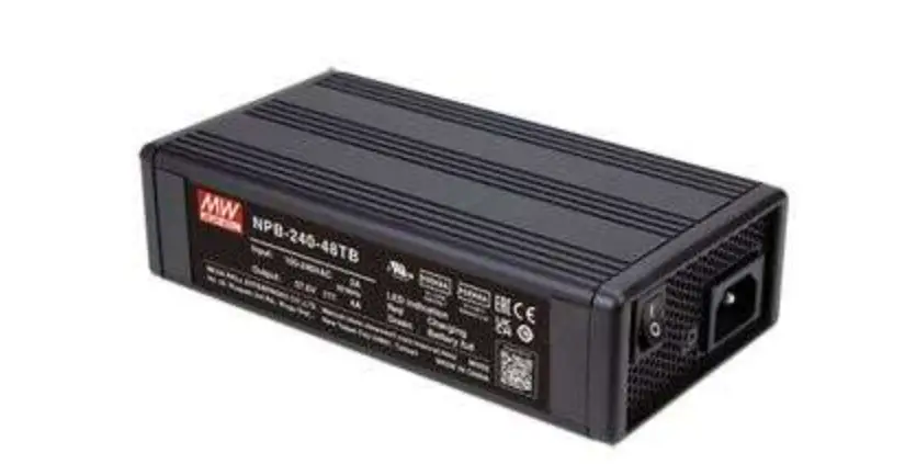
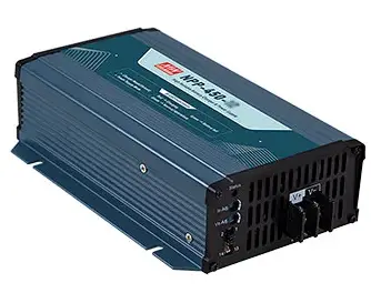
MEAN WELL NPP-450 Ultra Wide Output Range Battery Charger & Power Supply
Features
- Mulit-function single unit battery charger or power supply operation modes selectable
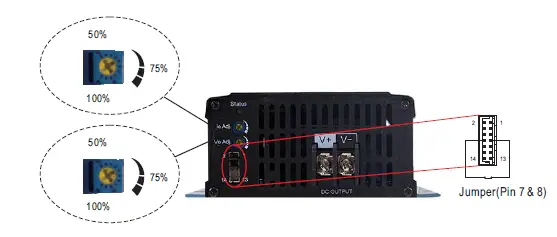
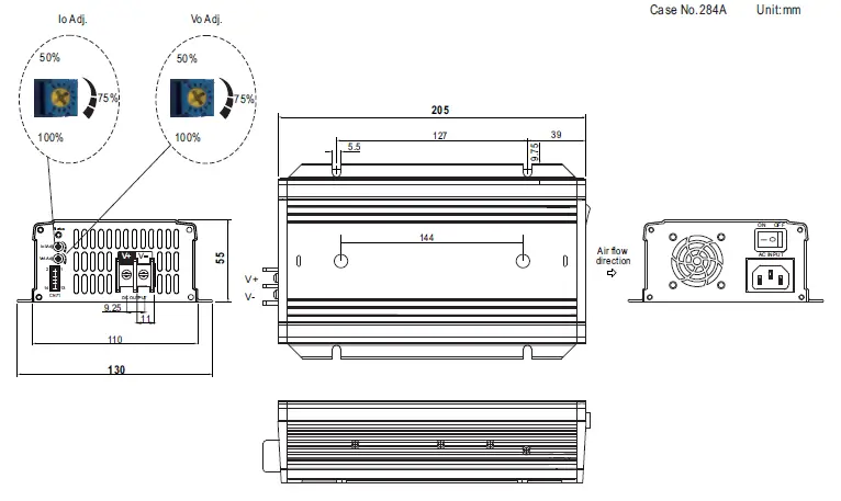
- Output voltage and current adjustable via potentiometer
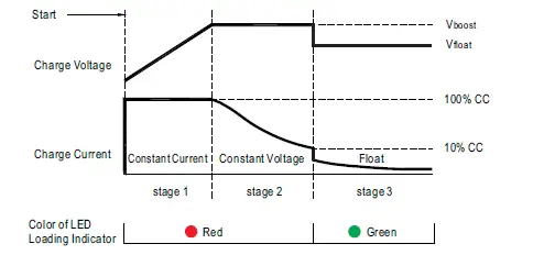
- 3-stage charging curve for charging mode
- -30~+70℃ wide operating temperature
- Multiple protections: Short circuit / Over load / Over voltage / Over temperature
- Thermal controlled DC fan for noise reduction
- Remote ON-OFF control
- Comply with 62368-1+60335-1/-2-29 dual certification
- Suitable for lead-acid (Pb) batteries
- Carry handle accessory available (Order NO.:DS-Carry handle, sold separately)
- 3 years warranty
Applications
- Radio system backup solution
- Electric scooter charger
- Camping car、Buses、Heavy duty truck、 Specialty vehicles
- Surveillance system
- Industrial automation machinery
- Industrial control system
- Mechanical and electrical equipment
Description
NPP-450 is a miniaturized dual-purpose charger and power supply. In addition to being used as a three- stage charger for lead-acid batteries, it can also be used as a constant voltage output power supply to drive general load. The operating mode can be quickly switched by plugging or unplugging a connector on the front panel. Other features include: ultra-wide voltage output, adjustable voltage via VR on the panel (10.5~21V, 21~42V, 42~80V, 54~100V), adjustable charging current (50~100%), built-in intelligent fan with variable speed based on temperature to reduce noise and extend fan lifetime, – 30~+70° C wide operating temperature, suitability for use in different environments, built-in remote ON/OFF control, compliance to IEC/EN/UL62368-1 and household EN60335-1/-2-29 dual safety, multiple built-in protections, and 3-year warranty. The NPP-450 is truly an intelligent, safe, and reliable universal dual-purpose charger and power supply with outstanding cost performance
Model Encoding

SPECIFICATION for Battery Charger mode (Default)
| MODEL | NPP-450-12 | NPP-450-24 | NPP-450-48 | NPP-450-72 | |||
|
OUTPUT | BOOST CHARGE VOLTAGE(Vboost)(default) | 14.4V | 28.8V | 57.6V | 72V | ||
| FLOAT CHARGE VOLTAGE(Vfloat)(default) | 13.8V | 27.6V | 55.2V | 69V | |||
| VOLTAGE ADJUSTABLE RANGE | 10.5 ~ 21V | 21 ~ 42V | 42 ~ 80V | 54 ~ 100V | |||
| By built-in potentionmeter | |||||||
| MAX. OUTPUT CURRENT(CC) | 25A | 13.5A | 6.8A | 5.5A | |||
| CURRENT ADJUSTABLE RANGE Note.3 | 12.5 ~ 25A | 6.75 ~ 13.5A | 3.4 ~ 6.8A | 2.75 ~ 5.5A | |||
| By built-in potentionmeter | |||||||
| MAX. POWER | 420W | 453.6W | 456.96W | 462W | |||
| RECOMMENDED BATTERY CAPACITY (AMP HOURS) Note.4 | 90 ~ 300AH | 45 ~ 155AH | 24 ~ 80AH | 19 ~ 64AH | |||
|
INPUT | VOLTAGE RANGE Note.5 | 90 ~ 264VAC 127 ~ 370VDC | |||||
| FREQUENCY RANGE | 47 ~ 63Hz | ||||||
| POWER FACTOR (Typ.) | PF>0.98/115VAC, PF>0.95/230VAC at full load | ||||||
| EFFICIENCY (Typ.) Note.6 | 92% | 93% | 93% | 93% | |||
| AC CURRENT (Typ.) | 4.5A/115VAC 2.2A/230VAC | ||||||
| INRUSH CURRENT (Typ.) | COLD START 50A at 230VAC | ||||||
|
PROTECTION | SHORT CIRCUIT Note.7 | Protection type : Constant current limiting, charger will shutdown after 5 sec, re-power on to recover | |||||
| OVER VOLTAGE | 21.5 ~ 26V | 43 ~ 52V | 82 ~ 100V | 102 ~ 120V | |||
| Protection type : Shut down and latch off o/p voltage, re-power on to recover | |||||||
| OVER TEMPERATURE | Shut down O/P voltage, recovers automatically after temperature goes down | ||||||
|
FUNCTION | CHARGING STAGE | 3 stage only | |||||
| CHARGER OK SIGNAL | The TTL signal out, Charger OK = H(4.5 ~ 5.5V) ; Charger failure or protection status =L( -0.5 ~ +0.5V) | ||||||
| BATTERY FULL SIGNAL | The TTL signal out, Battery full = H(4.5 ~ 5.5V ); Charging = L(-0.5 ~ +0.5V) | ||||||
| REMOTE CONTROL | Open : Charger stop charging Short : Charger normal work | ||||||
| FAN SPEED CONTROL | Depends on internal temperature | ||||||
|
ENVIRONMENT | WORKING TEMP. | -30 ~ +70℃ (Refer to “Derating Curve”) | |||||
| WORKING HUMIDITY | 20 ~ 95% RH non-condensing | ||||||
| STORAGE TEMP., HUMIDITY | -40 ~ +85℃, 10 ~ 95% RH non-condensing | ||||||
| TEMP. COEFFICIENT | ±0.05%/℃ (0 ~ 50℃) | ||||||
| VIBRATION | 10 ~ 500Hz, 2G 10min./1cycle, 60min. each along X, Y, Z axes | ||||||
|
SAFETY & EMC (Note 8) | SAFETY STANDARDS | CB IEC62368-1,IEC60335-1/2-29, Dekra BS EN/EN62368-1,BS EN/EN60335-1/2-29, UL62368-1, EAC TP TC 004 approved | |||||
| WITHSTAND VOLTAGE | I/P-O/P:3KVAC I/P-FG:2KVAC O/P-FG:0.5KVAC | ||||||
| ISOLATION RESISTANCE | I/P-O/P, I/P-FG, O/P-FG:100M Ohms / 500VDC / 25℃/ 70% RH | ||||||
|
EMC EMISSION | Parameter | Standard | Test Level / Note | ||||
| Conducted | BS EN/EN55032 (CISPR32),BS EN/EN55014-1 | Class B | |||||
| Radiated | BS EN/EN55032 (CISPR32),BS EN/EN55014-1 | Class B | |||||
| Harmonic Current | BS EN/EN61000-3-2 | Class A | |||||
| Voltage Flicker | BS EN/EN61000-3-3 | —– | |||||
|
EMC IMMUNITY | BS EN/EN61000-6-2 | ||||||
| Parameter | Standard | Test Level / Note | |||||
| ESD | BS EN/EN61000-4-2 | Level 3, 8KV air ; Level 2, 4KV contact | |||||
| Radiated | BS EN/EN61000-4-3 | Level 2, 3V/m | |||||
| EFT / Burst | BS EN/EN61000-4-4 | Level 2, 1KV | |||||
| Surge | BS EN/EN61000-4-5 | Level 2, 1KV/Line-Line,Level 3, 2KV/Line-Earth | |||||
| Conducted | BS EN/EN61000-4-6 | Level 2, 3Vrms | |||||
| Magnetic Field | BS EN/EN61000-4-8 | Level 1, 1A/m | |||||
| Voltage Dips and Interruptions | BS EN/EN61000-4-11 | >95% dip 0.5 periods, 30% dip 25 periods, >95% interruptions 250 periods | |||||
| OTHERS | MTBF | 352.3K hrs min. Telcordia SR-332 (Bellcore) ; 118.5K hrs min. MIL-HDBK-217F (25℃) | |||||
| DIMENSION | 205*130*55mm (L*W*H) | ||||||
| PACKING | 1.02Kg; 8pcs/ 10Kg / 1.71CUFT | ||||||
|
NOTE |
Product Liability Disclaimer:For detailed information, please refer to https://www.meanwell.com/serviceDisclaimer.aspx | ||||||
SPECIFICATION for Power Supply mode (Selectable via pin3 & 4 jumper of 14pins connector on panel)
| MODEL | NPP-450-12 | NPP-450-24 | NPP-450-48 | NPP-450-72 | |||
|
OUTPUT | DC VOLTAGE | 14.4V | 28.8V | 57.6V | 72V | ||
| VOLTAGE ADJUSTABLE RANGE | 10.5 ~ 21V | 21 ~ 42V | 42 ~ 80V | 54 ~ 100V | |||
| By built-in potentionmeter | |||||||
| CURRENT ADJUSTABLE RANGE | 12.5 ~ 25A | 6.75 ~ 13.5A | 3.4 ~ 6.8A | 2.75 ~ 5.5A | |||
| RATED CURRENT | 25A | 13.5A | 6.8A | 5.5A | |||
| RATED POWER | 420W | 453.6W | 457W | 462W | |||
| RIPPLE & NOISE(max.) | 180mVp-p | 300mVp-p | 480mVp-p | 600mVp-p | |||
| VOLTAGE TOLERANCE | ±1.0% | ±1.0% | ±1.0% | ±1.0% | |||
| LINE REGULATION | ±0.5% | ±0.5% | ±0.5% | ±0.5% | |||
| LOAD REGULATION | ±1.0% | ±1.0% | ±0.5% | ±0.5% | |||
| SETUP, RISE TIME | 1800ms, 60ms/230VAC at full load | ||||||
| HOLD UP TIME (Typ.) | 16ms/230VAC at 75% load 10ms/230VAC at full load | ||||||
|
INPUT | VOLTAGE RANGE Note.3 | 90 ~ 264VAC 127 ~ 370VDC | |||||
| FREQUENCY RANGE | 47 ~ 63Hz | ||||||
| POWER FACTOR (Typ.) | PF>0.98/115VAC, PF>0.95/230VAC at full load | ||||||
| EFFICIENCY (Typ.) | 92% | 93% | 93% | 93% | |||
| AC CURRENT (Typ.) | 4.5A/115VAC 2.2A/230VAC | ||||||
| INRUSH CURRENT (Typ.) | COLD START 50A at 230VAC | ||||||
|
PROTECTION | OVERLOAD | 105 ~ 115% rated output power | |||||
| Protection type : Constant current limiting, unit will shutdown after 5 sec, re-power on to recover | |||||||
| SHORT CURRENT | Protection type : Constant current limiting, unit will shutdown after 5 sec, re-power on to recover | ||||||
| OVER VOLTAGE | 21.5 ~ 26V | 43 ~ 52V | 82 ~ 100V | 102 ~ 120V | |||
| Protection type : Shut down and latch off o/p voltage, re-power on to recover | |||||||
| OVER TEMPERATURE | Shut down O/P voltage, recovers automatically after temperature goes down | ||||||
| FUNCTION | REMOTE CONTROL | Open : Power OFF Short : Power ON | |||||
| DC OK | The TTL signal out, DC OK = H(4.5 ~ 5.5V) ; Power supply failure or protection = L(-0.5 ~ +0.5V) | ||||||
| FAN SPEED CONTROL | Depends on internal temperature | ||||||
|
ENVIRONMENT | WORKING TEMP. | -30 ~ +70℃ (Refer to “Derating Curve”) | |||||
| WORKING HUMIDITY | 20 ~ 95% RH non-condensing | ||||||
| STORAGE TEMP., HUMIDITY | -40 ~ +85℃, 10 ~ 95% RH non-condensing | ||||||
| TEMP. COEFFICIENT | ±0.05%/℃ (0 ~ 50℃) | ||||||
| VIBRATION | 10 ~ 500Hz, 2G 10min./1cycle, 60min. each along X, Y, Z axes | ||||||
|
SAFETY & EMC (Note 4) | SAFETY STANDARDS | CB IEC62368-1,IEC60335-1/2-29, Dekra BS EN/EN62368-1,BS EN/EN60335-1/2-29, UL62368-1, EAC TP TC 004 approved | |||||
| WITHSTAND VOLTAGE | I/P-O/P:3KVAC I/P-FG:2KVAC O/P-FG:0.5KVAC | ||||||
| ISOLATION RESISTANCE | I/P-O/P, I/P-FG, O/P-FG:100M Ohms / 500VDC / 25℃/ 70% RH | ||||||
|
EMC EMISSION | Parameter | Standard | Test Level / Note | ||||
| Conducted | BS EN/EN55032 (CISPR32),BS EN/EN55014-1 | Class B | |||||
| Radiated | BS EN/EN55032 (CISPR32),BS EN/EN55014-1 | Class B | |||||
| Harmonic Current | BS EN/EN61000-3-2 | Class A | |||||
| Voltage Flicker | BS EN/EN61000-3-3 | —– | |||||
|
EMC IMMUNITY | BS EN/EN61000-6-2 | ||||||
| Parameter | Standard | Test Level / Note | |||||
| ESD | BS EN/EN61000-4-2 | Level 3, 8KV air ; Level 2, 4KV contact | |||||
| Radiated | BS EN/EN61000-4-3 | Level 2, 3V/m | |||||
| EFT / Burst | BS EN/EN61000-4-4 | Level 2, 1KV | |||||
| Surge | BS EN/EN61000-4-5 | Level 2, 1KV/Line-Line,Level 3, 2KV/Line-Earth | |||||
| Conducted | BS EN/EN61000-4-6 | Level 2, 3Vrms | |||||
| Magnetic Field | BS EN/EN61000-4-8 | Level 1, 1A/m | |||||
| Voltage Dips and Interruptions | BS EN/EN61000-4-11 | >95% dip 0.5 periods, 30% dip 25 periods, >95% interruptions 250 periods | |||||
| OTHERS | MTBF | 352.3K hrs min. Telcordia SR-332 (Bellcore) ; 118.5K hrs min. MIL-HDBK-217F (25℃) | |||||
| DIMENSION | 205*130*55mm (L*W*H) | ||||||
| PACKING | 1.02Kg; 8pcs/ 10Kg / 1.71CUFT | ||||||
|
NOTE |
※ Product Liability Disclaimer:For detailed information, please refer to https://www.meanwell.com/serviceDisclaimer.aspx | ||||||
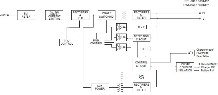
Block Diagram
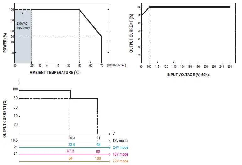
Derating Curve
Function Manual
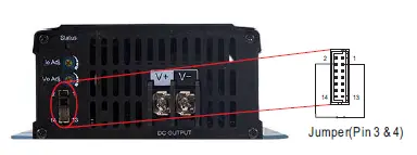
- Battery Charger or Power Supply Operation modes selectable via pin3 and pin4 jumper

Between pin3 and pin4 Operation modes Jumper connected Power supply mode Jumper removed Battery charger mode (Default) - Charging Curve (Charging Mode)

State NPP-450-12 NPP-450-24 NPP-450-48 NPP-450-72 Constant Current 25A 13.5A 6.8A 5.5A Vboost 14.4V 28.8V 57.6V 72V Vfloat 13.8V 27.6V 55.2V 69V 
- Charger OK / DC OK Signal
Charger OK / DC OK signal is a TTL level signal. The maximum sourcing current is 10mACharger OK / DC OK signal Charger status “High” : 4.5 ~ 5.5V Work normally “Low” : -0.5 ~ 0.5V Failure or protection function activated - Remote ON-OFF Control
The NPP-450 can be turned ON/OFF by using the “Remote Control” function.Between pin7 remote ON-OFF and pin8 +12Vaux Charger status Short ( Pin 7 = 10.8 ~ 13.2V) ON (Default) Open ( Pin 7 = -0.5 ~ 0.5V) OFF
Mechanical Specification
- Connector Pin No. Assignment : HRS DF11-14DP-2DS or equivalent
Pin No. Assignment Mating Housing Terminal 1,2,11~14 NC HRS DF11-14DS
or equivalentHRS DF11-**SC
or equivalent3,4 Battery Charger or Power Supply mode selectable 5 Battery Full 6 Charger OK (Charger mode) or DC OK (Power supply mode) 7 Remote ON-OFF 8 +12V-AUX 9,10 GND-AUX - LED Status Table
Charger (Default) LED Indicator Status Green Float stage (stage 3) or full charged Red Charging (stage 1 or stage 2) No Light Abnormal Power supply mode LED Indicator Status Green Normal working No Light Abnormal - Control Pin No. Assignment : HRS DF11-14DP-2DS or equivalent
Mating Housing HRS DF11-14DS or equivalent Terminal HRS DF11-**SC or equivalent
| Pin No. | Function | Description |
| 1,2,11~14 | NC | —– |
| 3,4 | Battery charger / Power supply | Open: Battery charger, Color of LED loading indicator: Reference to battery charger. Short: Power supply, Color of LED loading indicator :Green. |
| 5 | Battery Full | Battery Full Signal, referenced to GND-AUX(Pin 9 & 10). The Signal is a TTL level signal. The maximum sourcing current is 10mA and only for output.(Note.2) Low (-0.5 ~ 0.5V) : When the battery is charging. High (4.5 ~ 5.5V) : When the battery is full. |
| 6 | Charger OK / DC OK | Charger OK / DC OK Signal, referenced to GND-AUX(Pin 9 & 10). The Signal is a TTL level signal. The maximum sourcing current is 10mA and only for output.(Note.2) Low (-0.5 ~ 0.5V) : When the charger fails or the protect function is activating. High (4.5 ~ 5.5V) : When the charger is working properly. |
| 7 | Remote ON-OFF | Remote charger ON/OFF Function. The charger can turn the output ON/OFF by dry contact between Remote ON-OFF and +12V-AUX.(Note.2) Short (10.8 ~ 13.2V) : Charger ON ; Open(-0.5 ~ 0.5V) : Charger OFF ; The maximum input voltage is 13.2V. |
| 8 | +12V-AUX | It is controlled by the Remote ON-OFF control. |
| 9,10 | GND-AUX | The signal return is isolated from the output terminal. (+V & -V) |
Note1: Non-isolated signal, referenced to [GND(signal)].
Note2: Isolated signal, referenced to GND-AUX
Accessory List
Battery Charger or Power Supply mode of pin 3 and pin 4 mating pin along with NPP-450 (Standard accessory)
| Pin 3 and Pin 4 mating pin | Quantity |
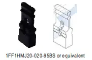 1FF1HMJ20-020-95BS or equivalent 1FF1HMJ20-020-95BS or equivalent | 1 |
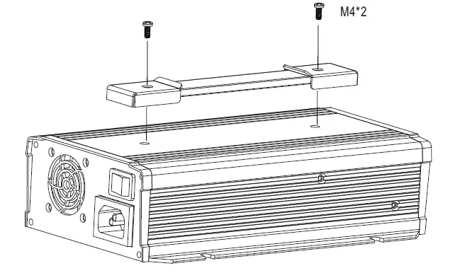
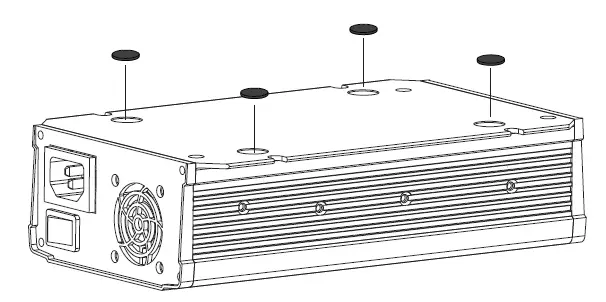
Carry handle (Optional accessory, battery charger and pull handle should be ordered seperately)
| MW’s Order No. | Item | Quantity | |
| DS-Carry Handle | 1 |  Handle Handle | 1 |
| 2 |  Foot pad Foot pad | 4 | |
| 3 |  Screw Screw | 2 | |
- Handle

- Foot pad

INSTALLATION MANUAL
Please refer to : http://www.meanwell.com/manual.html


