![]()
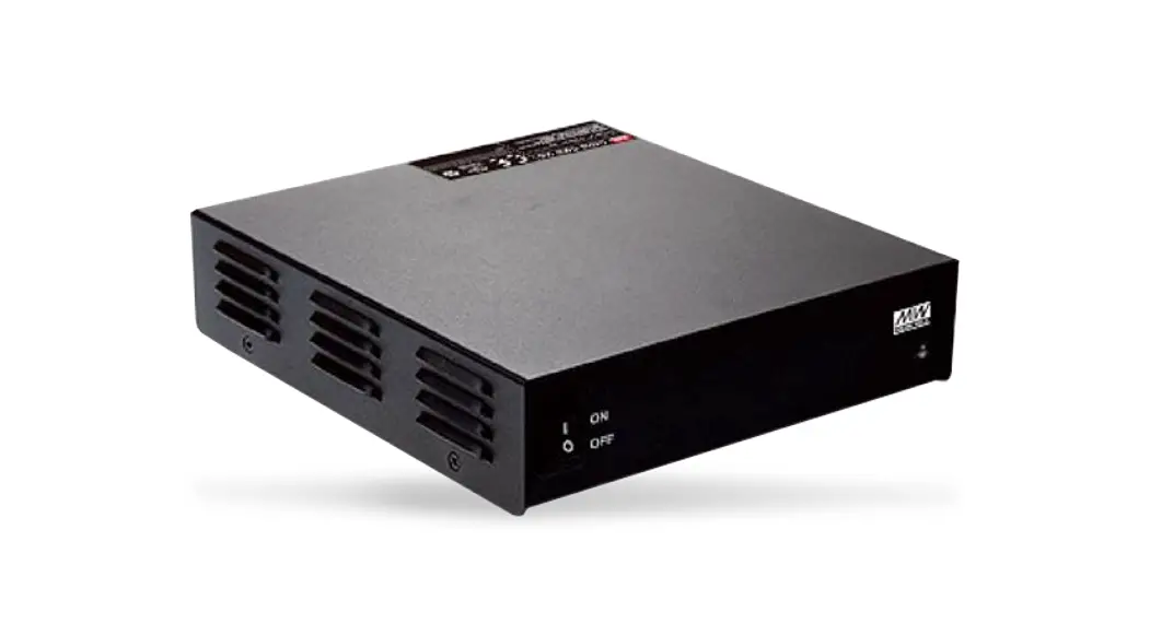
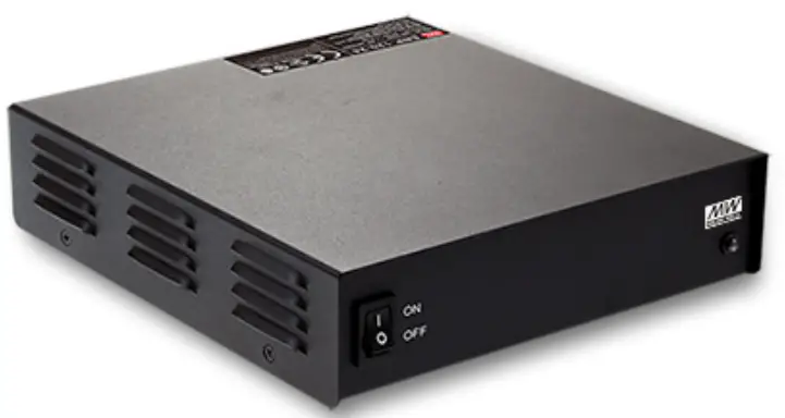
360W Programmable Desktop Type Battery Charger
ENC – 360 series
ENC-360 Series 360W Programmable Desktop Type Battery Charger
 |  |
| https://www.meanwell.com/webapp/product/search.aspx?prod=ENC-360&pdf=RU5DLUUucGRm&a=4 | https://www.youtube.com/watch?v=JIPKy0rufsQ&list=PLvUyt_OJELVrHoIIRgvHF2NQ-j39-NH-J&index=17 |

Features
- Charger for lead-acid batteries (flooded, Gel and AGM) and li-ion batteries (lithium iron and lithium manganese)
- Built-in 3 stage programmable charging curve
- Universal AC input / Full range
- Built-in active PFC function
- Fanless design, cooling by free air convection
- Built-in temperature compensation function
- Protection: Short circuit / Over voltage /Over temperature / Battery under voltage / Battery over voltage / Battery reverse polarity protection
- 3 years warranty
Applications
- Radio system backup solution
- Electric scooter charger
- Surveillance system
■ GTIN CODE
MW Search https://www.meanwell.comiserviceGTIN.aspx
Description
ENC-360 is a single output 360W AC/DC desktop type charger with 3 stage charging curve. In addition to the embedded pre-defined charging curves, the default curve is programmable and thus able to accommodate different types of batteries, such as lead-acid batteries (gel, flooded and AGM) and li-ion batteries (lithium iron and lithium manganese). With the rugged mechanical design along with the high efficiency circuitry, ENC-360 operates for the ambient temperature range -30–F70°C under free air convection.
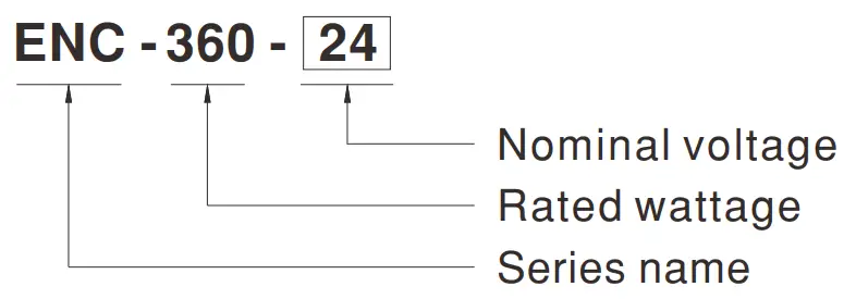
■ Model Encoding
SPECIFICATION
| MODEL | ENC-360-12 | ENC-380-24 | ENC-360-48 | |
| OUTPUT | BOOM CHAFtGEVIXTAGE(Wlea)0661411 | 14AV | 28.8V | 57.6V |
| FLOAT GORGE VOLTAGEiroltKOINIP | I 3.I3V | 27.6V | 552V | |
| CHARGE VOLTAGE RANGE NS3 | 9 – 15V | 18 – 30V | 38 – 80V | |
| OUTPUT CURRENT(CC) (default) | 24A | 12A | 6A | |
| RATED POWER | 345.6W | 345.6W | 345.6W | |
| RECOMMENDED BATTERY CAPACITY (AMP HOURS) Nola | 85 – 250AH | 45 – 125AH | 25 – t35AH | |
| LEAKAGE CURRENT FROM BATTERY (Typ.) | <1mA | |||
| INPUT | VOLTAGE RANGE Nowa | 90- 264VAC 127 – 370VDC | ||
| FREQUENCY RANGE | 47 -83Hz | |||
| POWER FACTOR (Typ.) | PF>0.98/115VAC. PF>0.95/230VAC at full load | |||
| EFFICIENCY (Typ.) | 91% 193% [ 94% | |||
| AC CURRENT (Typ.) | 3.8A/115VAC 1.9Al230VAC | |||
| INRUSH CURRENT (Typ.) | COLD START 80A at 230VAC | |||
| LEAKAGE CURRENT | <3.5mA I 240VAC | |||
| PROTECTION | SHORT CIRCUIT Nate | Protection type : Shut down 0/P voltage, re-power on to recover | ||
| OVER VOLTAGE Note.? | 15.5 – 18.2V 131 -38.5V 162.1 -72.9V | |||
| Protection type : Shut down and latch off de voltage. re-power on to recover | ||||
| REVERSE POLARITY | By intemal fuse | |||
| OVER TEMPERATURE | Shutdown 0/P voltage. recovers automatically after temperature goes down | |||
| FUNCTION | TEMPERATURECOMPFJ15A11011 | By NTC | ||
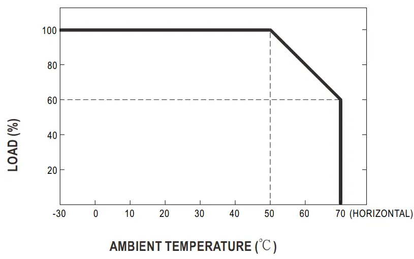
| EIMROMENT | WORKING TEMP. | -30- +70.0 (Refer to ‘Derating Curve’) | ||
| WORKING HUMIDITY | 20 – 95% RH non-condensing | |||
| STORAGE TEMP.. HUMIDITY | -40- .1.81C. 10 – 95%RM non-condensing | |||
| TEMP. COEFFICIENT | ± o.ostic (0- sot ) | |||
| VIBRATION | 10- 500Hz. 2G 10minilcycle.80min. each along X. Y. Z axes | |||
| SAFETY & EMC (Note a) | SAFETY STANDARDS | IEC82388-1. UL823138-1. EACTP TC 004. IISMICNS14338-1, J82388-1(2020)(Only for 12V) approved: Meet BS EN/ENI32388-1 | ||
| WITHSTAND VOLTAGE | 1112-0/P:3KVAC IIP-FG:2KVAC 0/P-FG:0.5KVAC | |||
| ISOLATION RESISTANCE | UP-0/P. UP-Fa 0/P-FG:100M Ohms / 500VDC / 25’C/ 70% RH | |||
| EMC EMISSION | Parameter | Standard | Test Level / Note | |
| Conducted | ISENE1455CO2(05aR32)/FCCRIRT15(C6FR.12) | Class B | ||
| Radiated | BSENEM32 (CSPR32) I FCCPARTIKSPRZ2) | Class El | ||
| Harmonic Current | BS ENIEN81000-3-2 | – | ||
| Vohage Picker | BS EN/EN61000-3-3 | – | ||
| EMC IMMUNITY | BS ENJEN55035. BSMI CN513438: J5503 (H29) (Only for 12V) | |||
| Parameter | Standard | Test Level / Note | ||
| ESD | EIS ENIEN81000-4-2 | Level 3. 8KV air : Level 2. MN contact | ||
| Radiated | BS EN/EN81000-4-3 | Level 2. 3V/m | ||
| EFT/Bust | BS EN/041310034-4 | Level 2. 1KV | ||
| Surge | BS EN/EN81000-4-5 | Level 2. IKVILine-Linelevel 3. 2NY/tine-Earth | ||
| Conducted | BS ENIEN01000-443 | Level 2. 3Vrms | ||
| Magnetic Field | BS EN/EN61000-4-8 | Level I. lAlm | ||
| Voltage Dips and IMenupticos | BS ENIEN81000-4-11 | >95% dip 0.5 periods. 30% dip 25 periods. >95% itterruptions 250 periods | ||
| OTHERS | MTBF | 1178.7K hrs min. Tekordia SR-332 (Bellcore) : 138.7K hrs min. MIL-HDBK-21 F (25C) | ||
| DIMENSION | 192’178’45.5mm (L’W’H) | |||
| PACKING | 1.5Kg: 10pcs/18Kg /1.38CUFT | |||
NOTE
- Modification for charger specification may be required for different battery specification. Please contact battery vendor and MEAN WELL for details.
- All parameters NOT specially mentioned are measured at 230VAC input. rated load and 25 (‘ of ambient temperature.
- This is the range when programming Vboost or Vfloat by using SBP-001. the smart battery charging programmer.
- This is MEAN WELL’s suggested range. Please consult your battery manufacturer for their suggestions about maximum charging current limitation.
- Derating may be needed under low input voltages. Please check the derating curve for more details.
- This protection mechanism is specified for the case the short circuit occurs after the charger is tumed on.
- Each model incorporates a MCU-controlled dynamic over voltage protection. which is about 115% of Vboost over Constant Current stage and Constant Voltage stage whereas 115% of Vf bat over Float stage.
- The battery charger is considered as an independent unit. but the final equipment still need to re-confirm that the whole system complies with the EMC directives. For guidance on how to perform these EMC tests. please refer to “EMI testing of component power supplies.” (as available on http://www.meanwell.com)
- The ambient temperature derating of 3.5 C/1000m with fanless models and of 5 (71000m with fan models for operating altitude higher than 2000m(6500ft). Product Liability Disclaimer : For detailed information. please refer to https://www.meanwell.com/serviceDisclaimetaspx
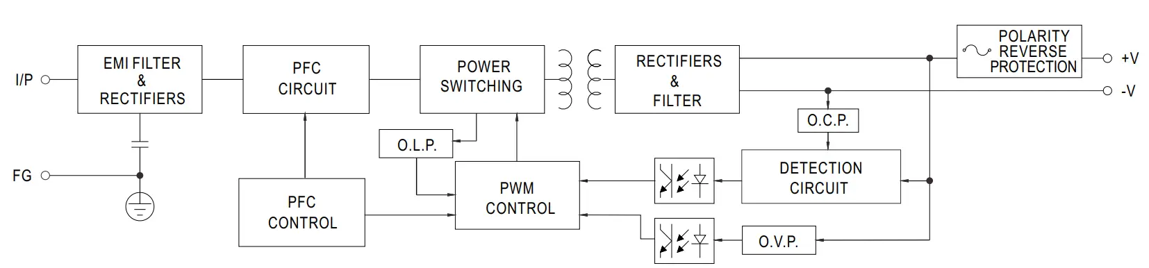
Block Diagram
Derating Curve
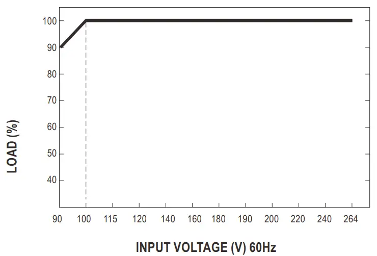
Static Characteristics
Function Manual
1.Charging Curve
※ This series provides a 3 stage charging. The default curve is programmable, whereas other pre-defined curves can be activated by the means of the DIP switch; please refer to the table below and the Mechanical Specification.
※ To accommodate the parameters of the charging curve, SBP-001, the smart battery charging programmer designed by MEAN WELL, and a personal computer are needed. Please contact MEAN WELL for details.
◎ Default 3 stage charging curve
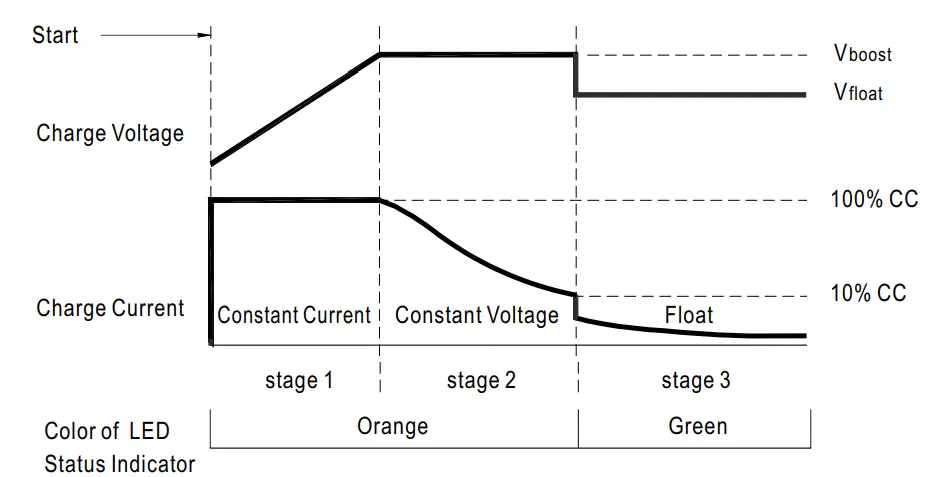
◎ Suitable for lead-acid batteries (flooded, Gel and AGM) and Li-ion batteries (lithium iron and lithium manganese).
◎ Embedded 3 stage charging curve
| MODEL | Description | CC(default) | Vboost | Vfloat |
| 12V | Default, programmable | 24A | 14. | 14. |
| Pre-defined, gel batter | 14 | 14. | ||
| Pre-defined, flooded battery | 14. | 13. | ||
| Pre-defined, AGM battery | 15. | 14. | ||
| 24V | Default, programmable | 12A | 29. | 28. |
| Pre-defined, gel battery | 28 | 27. | ||
| Pre-defined, flooded battery | 28. | 27. | ||
| Pre-defined, AGM battery | 29 | 27 | ||
| 48V | Default, programmable | 6A | 58. | 55. |
| Pre-defined, gel battery | 56 | 54. | ||
| Pre-defined, flooded battery | 57. | 54. | ||
| Pre-defined, AGM battery | 58 | 54 |
2. Front Panel LED Indicators & Corresponding Signal at Function Pins
| LED | Description |
| Float (stage 3) | |
| Charging (stage 1 or stage 2) |
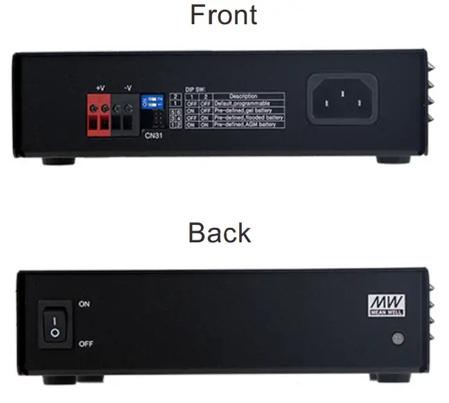
Mechanical Specification
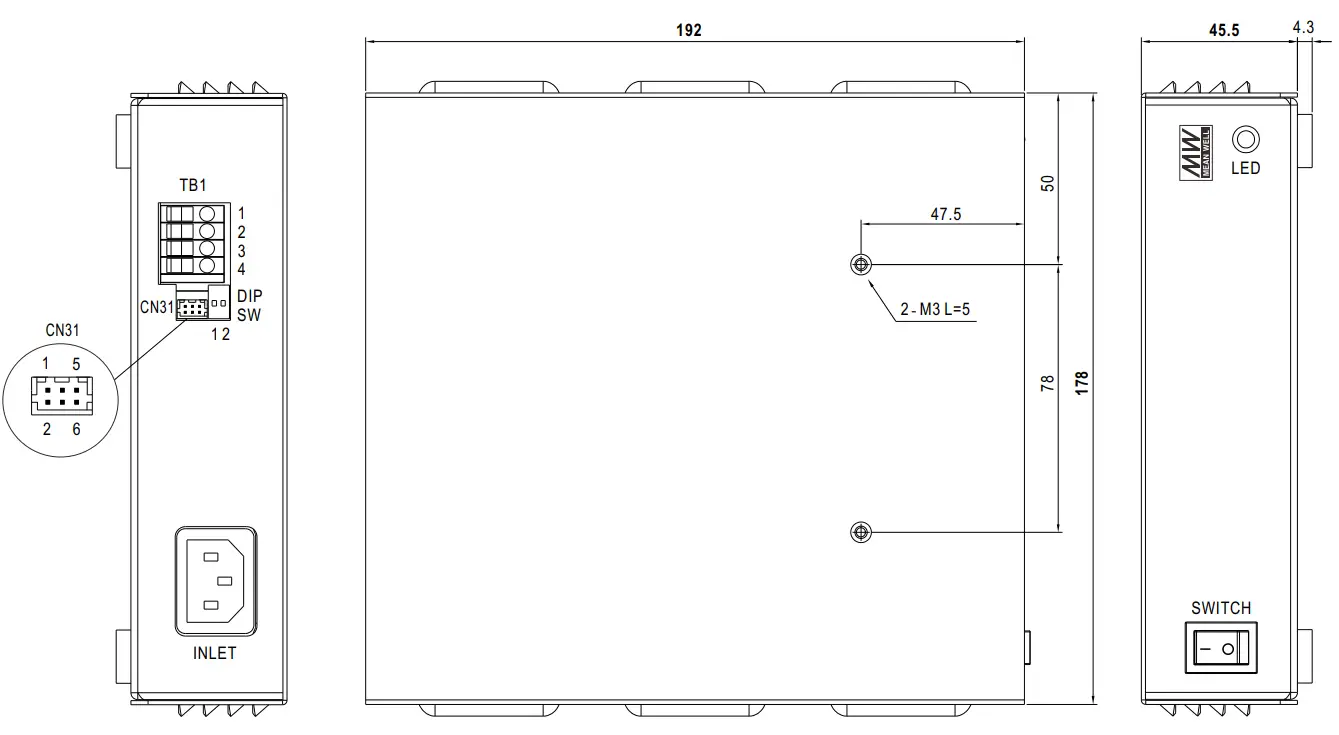
Terminal Pin No. Assignment (TB1):
| Pin No. | Assignment |
| 1,2 | +V |
| 3,4 | -V |
Note: Please use wires with a cross section of 0.5 – 4.0 mm2 (12~20AWG) for connection.
Recommended wires strip length is 9 mm and screw torque is 4.0 lb-inch (0.4~0.5Nm).
DIP SW:
| 1 | 2 | Description |
| OFF | OFF | Default, programmable |
| ON | OFF | Pre-defined, Gel battery |
| OFF | ON | Pre-defined, flooded battery |
| ON | ON | Pre-defined, AGM battery |
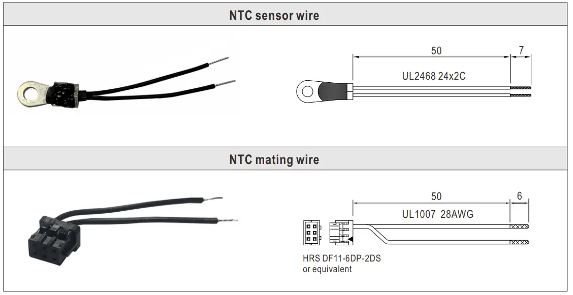
Connector Pin No. Assignment (CN31) :
HRS DF11-6DP-2DS or equivalent
| Pin No. | Assignment | Mating Housing | Terminal |
| 1 | Prog- +3.3V | HRS DF11-6DS or equivalent | HRS DF11-**SC or equivalent |
| 2 | Prog- GND | ||
| 3 | Prog- RX | ||
| 4 | Prog- TX | ||
| 5 | RTH+ | ||
| 6 | RTH- |
Accessory List
| Item | Quantity | |
| 1 | NTC sensor wire | 1 |
| 2 | NTC mating wire | 1 |