![]()
![]() 1200W High Reliable Ultra Wide Output Range Battery Charger & Power Supply 2-in-1
1200W High Reliable Ultra Wide Output Range Battery Charger & Power Supply 2-in-1
NPP-1200 series
Instruction Manual
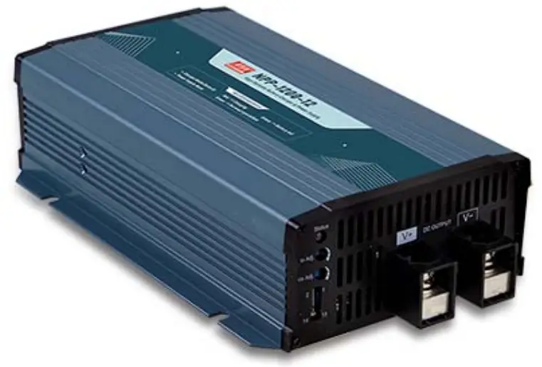
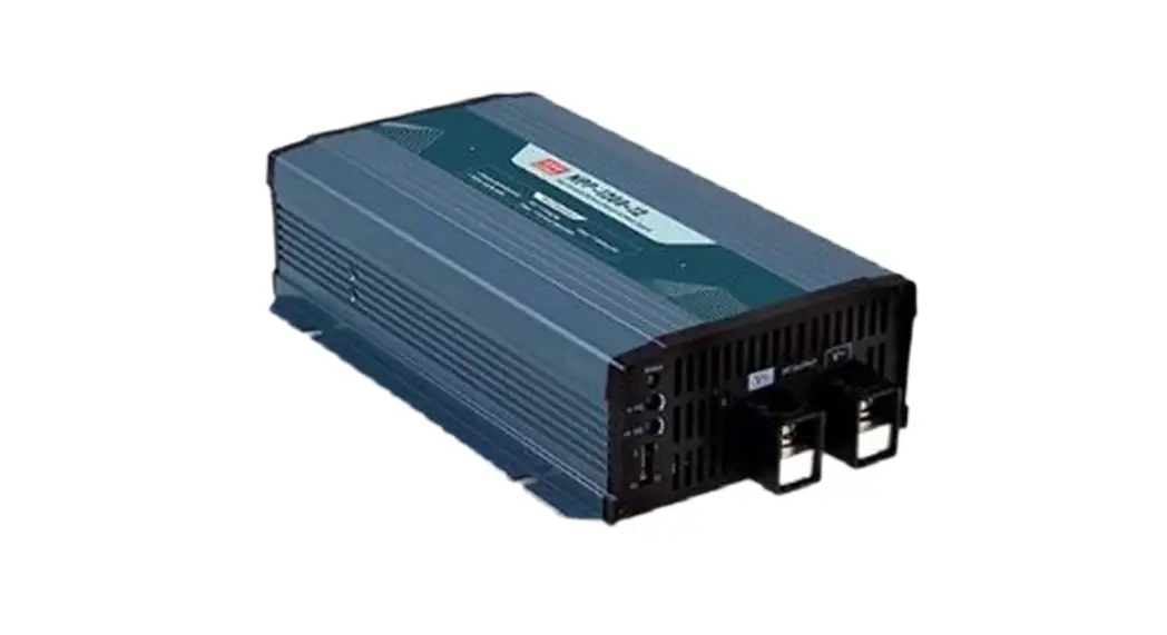
NPP-1200 Series 1200W High Reliable Ultra Wide Output Range Battery Charger & Power Supply
![]()

 https://www.meanwell.com/Upload/PDF/NPB,NPP-E.pdf
Features
- Mulit-function single unit battery charger or power supply operation modes selectable
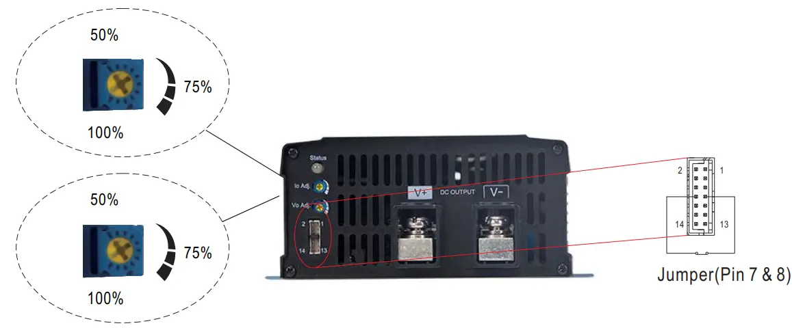
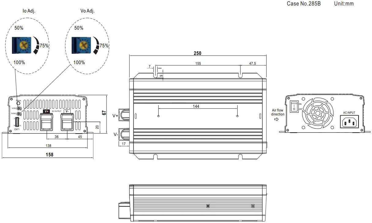
- Output voltage and current adjustable via potentiometer
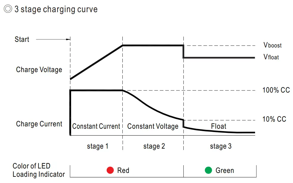
- 3-stage charging curve for charging mode
- -30–+70 C wide operating temperature
- Multiple protections: Short circuit / Over load / Over voltage / Over temperature
- Thermal controlled DC fan for noise reduction
- Remote ON-OFF control
- Comply with 62368-1 60335-1 -2-29 dual certification
Applications
- Radio system backup solution
- Electric scooter charger
- Camping car
- Buses
- Heavy duty truck
- Specialty vehicles
- Surveillance system
- Industrial automation machinery
- Industrial control system
- Mechanical and electrical equipment
- Suitable for lead-acid (Pb) batteries
- Carry handle accessory available (Order NO.:DS-Carry handle, sold separately)
- 3 years warranty
Description
NP P-1200 is a miniaturized dual-purpose charger and power supply. In addition to being used as a three-stage charger for lead-acid batteries, it can also be used as a constant voltage output power supply to drive general load. The operating mode can be quickly switched by plugging or unplugging a connector on the front panel. Other features include: ultra-wide voltage output, adjustable voltage via VR on the panel (10.5-21V, 21-42V, 42-80V), adjustable charging current (50-100%), built-in intelligent fan with variable speed based on temperature to reduce noise and extend fan lifetime, – 30- +70′ C wide operating temperature, suitability for use in different environments, built-in remote ON/OFF control, compliance to IEC/EN/UL62368-1 and household EN60335-1/-2-29 dual safety, multiple built-in protections, and 3-year warranty. The N PP-1200 is truly an intelligent, safe, and reliable universal dual-purpose charger and power supply with outstanding cost performance.
Model Encoding

SPECIFICATION for Battery Charger mode (Default)
| MODEL | NPP-1200-12 | NPP-1200-24 | NPP-1200-48 | ||
| OUTPUT | BOOST CHARGE VOLTAGE(Vboost)(default) | 14.4V | 28.8V | 57.6V | |
| FLOAT CHARGE VOLTAGE(Vfloat)(default) | 13.8V | 27.6V | 55.2V | ||
| VOLTAGE ADJUSTABLE RANGE | 10.5 ~ 21V | 21 ~ 42V | 42 ~ 80V | ||
| By built-in potentionmeter | |||||
| MAX. OUTPUT CURRENT(CC) | 70A | 36A | 18A | ||
| CURRENT ADJUSTABLE RANGE Note.3 | 35 ~ 70A | 18 ~ 36A | 9 ~ 18A | ||
| By built-in potentionmeter | |||||
| MAX. POWER | 1176W | 1209.6W | 1209.6W | ||
| RECOMMENDED BATTERY CAPACITY (AMP HOURS) Note.4 | 240 ~ 800AH | 120 ~ 420AH | 60 ~ 210AH | ||
| INPUT | VOLTAGE RANGE | Note.5 | 90 ~ 264VAC 127 ~ 370VDC | ||
| FREQUENCY RANGE | 47 ~ 63Hz | ||||
| POWER FACTOR (Typ.) | PF>0.98/115VAC, PF>0.95/230VAC at full load | ||||
| EFFICIENCY (Typ.) | Note.6 | 92% | 93% | 94% | |
| AC CURRENT (Typ.) | 12A/115VAC 6.5A/230VAC | ||||
| INRUSH CURRENT (Typ.) | COLD START 50A at 230VAC | ||||
| PROTECTION | SHORT CIRCUIT | Note.7 | Protection type : Constant current limiting, charger will shutdown after 5 sec, re-power on to recover | ||
| OVER VOLTAGE | 21.5 ~ 26V | 43 ~ 52V | 82 ~ 100V | ||
| Protection type : Shut down and latch off o/p voltage, re-power on to recover | |||||
| OVER TEMPERATURE | Shut down O/P voltage, recovers automatically after temperature goes down | ||||
| FUNCTION | CHARGING STAGE | 3 stage only | |||
| CHARGER OK SIGNAL | The TTL signal out, Charger OK = H(4.5 ~ 5.5V) ; Charger failure or protection status =L( -0.5 ~ +0.5V) | ||||
| BATTERY FULL SIGNAL | The TTL signal out, Battery full = H(4.5 ~ 5.5V ); Charging = L(-0.5 ~ +0.5V) | ||||
| REMOTE CONTROL | Open : Charger stop charging Short : Charger normal work | ||||
| FAN ON/OFF CONTROL | Depends on internal temperature | ||||
| ENVIRONMENT | WORKING TEMP. | -30 ~ +70℃ (Refer to “Derating Curve”) | |||
| WORKING HUMIDITY | 20 ~ 95% RH non-condensing | ||||
| STORAGE TEMP., HUMIDITY | -40 ~ +85℃, 10 ~ 95% RH non-condensing | ||||
| TEMP. COEFFICIENT | ±0.05%/℃ (0 ~ 50℃) | ||||
| VIBRATION | 10 ~ 500Hz, 2G 10min./1cycle, 60min. each along X, Y, Z axes | ||||
| SAFETY & EMC (Note 8) | SAFETY STANDARDS | CB IEC62368-1,IEC60335-1/2-29, Dekra BS EN/EN62368-1,BS EN/EN60335-1/2-29, UL62368-1, EAC TP TC 004 approved | |||
| WITHSTAND VOLTAGE | I/P-O/P:3KVAC I/P-FG:2KVAC O/P-FG:0.5KVAC | ||||
| ISOLATION RESISTANCE | I/P-O/P, I/P-FG, O/P-FG:100M Ohms / 500VDC / 25℃/ 70% RH | ||||
| EMC EMISSION | Parameter | Standard | Test Level / Note | ||
| Conducted | BS EN/EN55032 (CISPR32),BS EN/EN55014-1 | Class B | |||
| Radiated | BS EN/EN55032 (CISPR32),BS EN/EN55014-1 | Class A | |||
| Harmonic Current | BS EN/EN61000-3-2 | Class A | |||
| Voltage Flicker | BS EN/EN61000-3-3 | —– | |||
| EMC IMMUNITY | Parameter | Standard | Test Level / Note | ||
| ESD | BS EN/EN61000-4-2 | Level 3, 8KV air ; Level 2, 4KV contact | |||
| Radiated | BS EN/EN61000-4-3 | Level 2, 3V/m | |||
| EFT / Burst | BS EN/EN61000-4-4 | Level 2, 1KV | |||
| Surge | BS EN/EN61000-4-5 | Level 2, 1KV/Line-Line,Level 3, 2KV/Line-Earth | |||
| Conducted | BS EN/EN61000-4-6 | Level 2, 3Vrms | |||
| Magnetic Field | BS EN/EN61000-4-8 | Level 1, 1A/m | |||
| Voltage Dips and Interruptions | BS EN/EN61000-4-11 | 95% dip 0.5 periods, 30% dip 25 periods, >95% interruptions 250 periods | |||
| OTHERS | MTBF | 208.4K hrs min. Telcordia SR-332 (Bellcore) ; 63.6K hrs min. | MIL-HDBK-217F (25℃) | ||
| DIMENSION | 250*158*67mm (L*W*H) | ||||
| PACKING | 1.93Kg; 4pcs/ 10Kg / 1.72CUFT | ||||
| NOTE | 1. Modification for charger specification may be required for different battery specification. Please contact battery vendor and MEAN WELL for details. 2. All parameters NOT specially mentioned are measured at 230VAC input, rated load and 25℃ of ambient temperature. 3. Float charge voltage(Vfloat) adjustable via potentiomerter in battery charger mode. 4. This is MEAN WELL’s suggested range. Please consult your battery manufacturer for their suggestions about maximum charging current limitation. 5. Derating may be needed under low input voltages. Please check the derating curve for more details. 6. The efficiency is measured at 16.8V charge voltage(12V model), 33.6V charge voltage(24V model), 67.2V charge voltage(48V model). 7. This protection mechanism is specified for the case the short circuit occurs after the charger is turned on. 8. The charger is considered a component which will be installed into a final equipment. All the EMC tests are been executed by mounting the unit on a 600mm*900mm metal plate with 1mm of thickness. The final equipment must be re-confirmed that it still meets EMC directives. For guidance on how to perform these EMC tests, please refer to “EMl testing of component power supplies.” (as available on http://www.meanwell.com) 9. The ambient temperature derating of 3.5℃/1000m with fanless models and of 5℃/1000m with fan models for operating altitude higher than 2000m(6500ft). ※ Product Liability Disclaimer:For detailed information, please refer to https://www.meanwell.com/serviceDisclaimer.aspx | ||||
SPECIFICATION for Power Supply mode (Selectable via pin3 & 4 jumper of 14pins connector on panel)
| MODEL | NPP-1200-12 | NPP-1200-24 | NPP-1200-48 | |
| OUTPUT | DC VOLTAGE | 14.4V | 28.8V | 57.6V |
| VOLTAGE ADJUSTABLE RANGE | 10.5 ~ 21V | 21 ~ 42V | 42 ~ 80V | |
| By built-in potentionmeter | ||||
| CURRENT ADJUSTABLE RANGE | 35 ~ 70A | 18 ~ 36A | 9 ~ 18A | |
| RATED CURRENT | 70A | 36A | 18A | |
| RATED POWER | 1176W | 1209.6W | 1209.6W | |
| RIPPLE & NOISE(max.) | 180mVp-p | 300mVp-p | 480mVp-p | |
| VOLTAGE TOLERANCE | ±1.0% | ±1.0% | ±1.0% | |
| LINE REGULATION | ±0.5% | ±0.5% | ±0.5% | |
| LOAD REGULATION | ±1.0% | ±1.0% | ±0.5% | |
| SETUP, RISE TIME | 1800ms, 60ms/230VAC at full load | |||
| HOLD UP TIME (Typ.) | 16ms/230VAC at 75% load 10ms/230VAC at full load | |||
| INPUT | VOLTAGE RANGE Note.3 | 90 ~ 264VAC 127 ~ 370VDC | ||
| FREQUENCY RANGE | 47 ~ 63Hz | |||
| POWER FACTOR (Typ.) | PF>0.98/115VAC, PF>0.95/230VAC at full load | |||
| EFFICIENCY (Typ.) | 92% | 93% | 94% | |
| AC CURRENT (Typ.) | 12A/115VAC 6.5A/230VAC | |||
| INRUSH CURRENT (Typ.) | COLD START 50A at 230VAC | |||
| PROTECTION | OVERLOAD | 105 ~ 115% rated output power | ||
| Protection type : Constant current limiting, unit will shutdown after 5 sec, re-power on to recover | ||||
| SHORT CIRCUIT | Protection type : Constant current limiting, unit will shutdown after 5 sec, re-power on to recover | |||
| OVER VOLTAGE | 21.5 ~ 26V | 43 ~ 52V | 82 ~ 100V | |
| Protection type : Shut down and latch off o/p voltage, re-power on to recover | ||||
| OVER TEMPERATURE | Shut down O/P voltage, recovers automatically after temperature goes down | |||
| FUNCTION | REMOTE CONTROL | Open : Power OFF Short : Power ON | ||
| DC OK | The TTL signal out, DC OK = H(4.5 ~ 5.5V) ; Power supply failure or protection = L(-0.5 ~ +0.5V) | |||
| FAN SPEED CONTROL | Depends on internal temperature | |||
| ENVIRONMENT | WORKING TEMP. | -30 ~ +70℃ (Refer to “Derating Curve”) | ||
| WORKING HUMIDITY | 20 ~ 95% RH non-condensing | |||
| STORAGE TEMP., HUMIDITY | -40 ~ +85℃, 10 ~ 95% RH non-condensing | |||
| TEMP. COEFFICIENT | ±0.05%/℃ (0 ~ 50℃) | |||
| VIBRATION | 10 ~ 500Hz, 2G 10min./1cycle, 60min. each along X, Y, Z axes | |||
| SAFETY & EMC (Note 4) | SAFETY STANDARDS | CB IEC62368-1,IEC60335-1/2-29, Dekra BS EN/EN62368-1,BS EN/EN60335-1/2-29, UL62368-1, EAC TP TC 004 approved | ||
| WITHSTAND VOLTAGE | I/P-O/P:3KVAC I/P-FG:2KVAC O/P-FG:0.5KVAC | |||
| ISOLATION RESISTANCE | I/P-O/P, I/P-FG, O/P-FG:100M Ohms / 500VDC / 25℃/ 70% RH | |||
| EMC EMISSION | Parameter | Standard | Test Level / Note | |
| Conducted | BS EN/EN55032 (CISPR32),BS EN/EN55014-1 | Class B | ||
| Radiated | BS EN/EN55032 (CISPR32),BS EN/EN55014-1 | Class A | ||
| Harmonic Current | BS EN/EN61000-3-2 | Class A | ||
| Voltage Flicker | BS EN/EN61000-3-3 | —– | ||
| EMC IMMUNITY | Parameter | Standard | Test Level / Note | |
| ESD | BS EN/EN61000-4-2 | Level 3, 8KV air ; Level 2, 4KV contact | ||
| Radiated | BS EN/EN61000-4-3 | Level 2, 3V/m | ||
| EFT / Burst | BS EN/EN61000-4-4 | Level 2, 1KV | ||
| Surge | BS EN/EN61000-4-5 | Level 2, 1KV/Line-Line,Level 3, 2KV/Line-Earth | ||
| Conducted | BS EN/EN61000-4-6 | Level 2, 3Vrms | ||
| Magnetic Field | BS EN/EN61000-4-8 | Level 1, 1A/m | ||
| Voltage Dips and Interruptions | BS EN/EN61000-4-11 | 95% dip 0.5 periods, 30% dip 25 periods, >95% interruptions 250 periods | ||
| OTHERS | MTBF | 208.4K hrs min. Telcordia SR-332 (Bellcore) ; 63.6K hrs min. MIL-HDBK-217F (25℃) | ||
| DIMENSION | 250*158*67mm (L*W*H) | |||
| PACKING | 1.93Kg; 4pcs/ 10Kg / 1.72CUFT | |||
| NOTE | 1. Modification for charger specification may be required for different battery specification. Please contact battery vendor and MEAN WELL for details. 2. All parameters NOT specially mentioned are measured at 230VAC input, rated load and 25℃ of ambient temperature. 3. Derating may be needed under low input voltages. Please check the derating curve for more details. 4. The PSU is considered a component which will be installed into a final equipment. All the EMC tests are been executed by mounting the unit on a 600mm*900mm metal plate with 1mm of thickness. The final equipment must be re-confirmed that it still meets EMC directives. For guidance on how to perform these EMC tests, please refer to “EMl testing of component power supplies.” (as available on http://www.meanwell.com) 5. The ambient temperature derating of 3.5℃/1000m with fanless models and of 5℃/1000m with fan models for operating altitude higher than 2000m(6500ft). ※ Product Liability Disclaimer:For detailed information, please refer to https://www.meanwell.com/serviceDisclaimer.aspx | |||
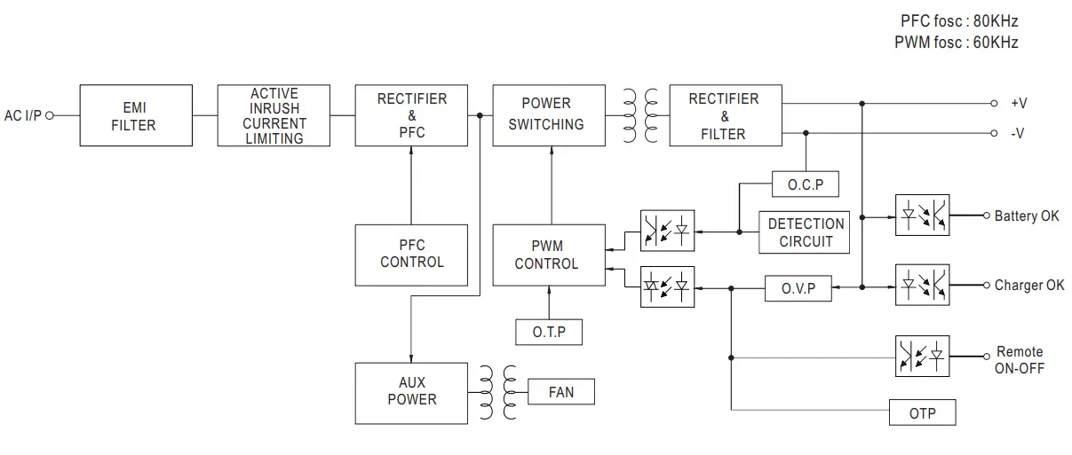
Block Diagram
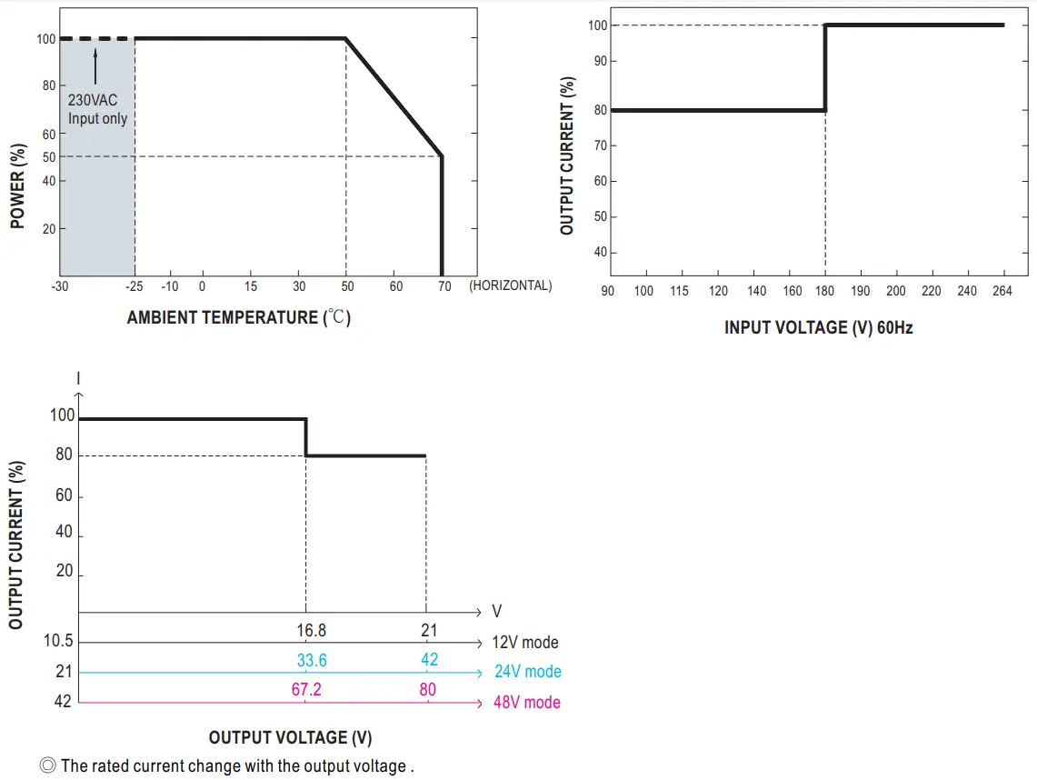
Derating Curve
Function Manual
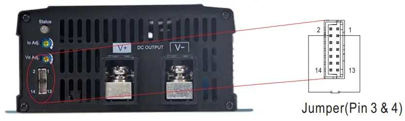
- Battery Charger or Power Supply Operation modes selectable via pin3 and pin4 jumper
Between pin3 and pin4 Operation modes Jumper connected Power supply mode Jumper removed Battery charger mode (Default) - Charging Curve (Charging Mode)

State NPP-1200-12 NPP-1200-24 NPP-1200-48 Constant
Current70A 36A 18A Vboost 14.4V 28.8V 57.6V Vfloat 13.8V 27.6V 55.2V ◎ Suitable for lead-acid batteries (flooded, Gel and AGM)
 ※ Vo x Io must be less than or equal to the rated power. Please refer to derating curve (page 4) .
 - Charger OK / DC OK Signal
Charger OK / DC OK signal is a TTL level signal.
The maximum sourcing current is 10mA.Charger OK / DC OK signal Charger status High : 4.5 ~ 5.5V Work normally Low : -0.5 ~ 0.5V Failure or protection function activated 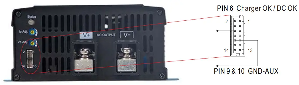
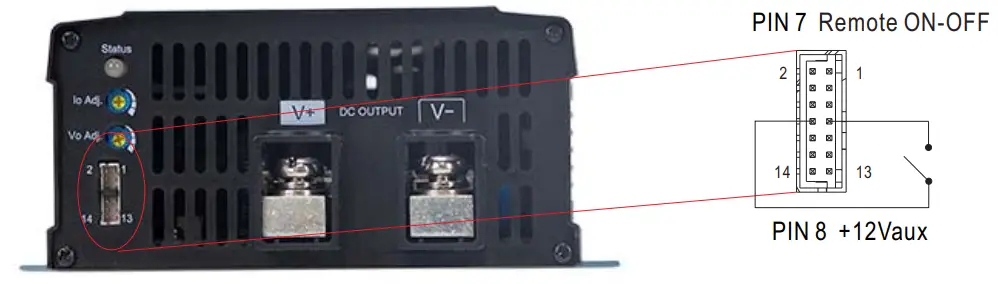
- Remote ON-OFF Control
The NPP-1200 can be turned ON/OFF by using the “Remote Control” function.Between pin7 remote ON-OFF and pin8 +12Vaux Charger status Short ( Pin 7 = 10.8 ~ 13.2V) ON (Default) Open Pin 7 = (-0.5 ~ 0.5V) OFF 
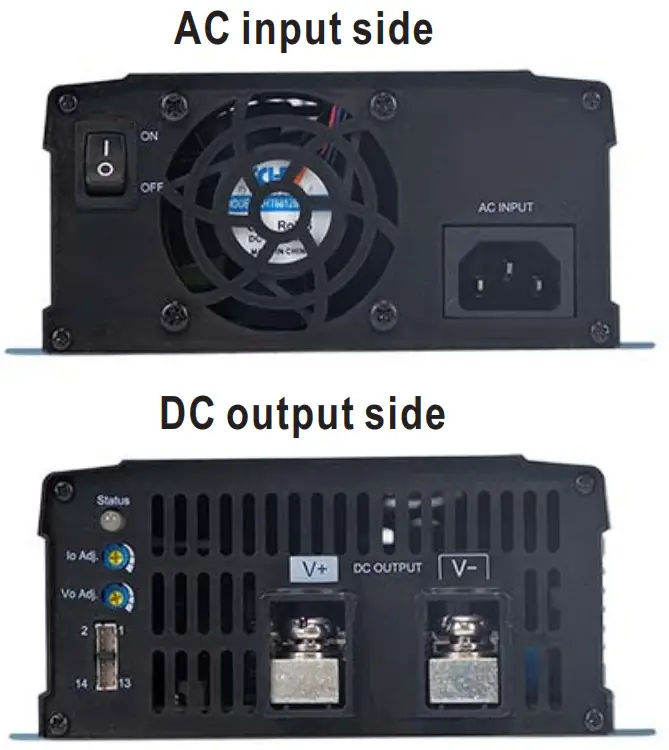
Mechanical Specification
※ Connector Pin No. Assignment : HRS DF11-14DP-2DS or equivalent
| Pin No. | Assignment | Mating Housing | Terminal |
| 1,2,11~14 | NC | HRS DF11-14DS or equivalent | HRS DF11-**SC or equivalent |
| 3,4 | Battery Charger or Power Supply mode selectable | ||
| 5 | Battery Full | ||
| 6 | Charger OK (Charger mode) or DC OK (Power supply mode) | ||
| 7 | Remote ON-OFF | ||
| 8 | +12V-AUX | ||
| 9,10 | GND-AUX |
※ LED Status Table
| Charger (Default) | |
| LED Indicator | Status |
| Float stage (stage 3) or full charged | |
| Charging (stage 1 or stage 2) | |
| Abnormal | |
| Power supply mode | |
| LED Indicator | Status |
| Normal working | |
| Abnormal | |
※ Control Pin No. Assignment : HRS DF11-14DP-2DS or equivalent
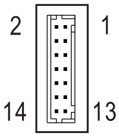
| Mating Housing | HRS DF11-14DS or equivalent |
| Terminal | HRS DF11-**SC or equivalent |
| Pin No. | Function | Description |
| 1,2,11-14 | NC | |
| 3,4 | Battery charger / Power supply | Open: Battery charger, Color of LED loading indicator: Reference to battery charger. Short: Power supply, Color of LED loading indicator :Green. |
| 5 | Battery Full | Battery Full Signal, referenced to GND-AUX(Pin 9 & 10). The Signal is a TTL level signal. The maximum sourcing current is 10mA and only for output.(Note.2) Low (-0.5 – 0.5V) : When the battery is charging. High (4.5 – 5.5V) : When the battery is full. |
| 6 | Charger OK / DC OK | Charger OK / DC OK Signal, referenced to GND-AUX(Pin 9 & 10). The Signal is a TTL level signal. The maximum sourcing current is 10mA and only for output.(Note.2) Low (-0.5 – 0.5V) : When the charger fails or the protect function is activating. High (4.5 – 5.5V) : When the charger is working properly. |
| 7 | Remote ON-OFF | Remote charger ON/OFF Function. The charger can turn the output ON/OFF by dry contact between Remote ON-OFF and +12V-AUX.(Note.2) Short (10.8 – 13.2V) : Charger ON ; Open(-0.5 – 0.5V) : Charger OFF ; The maximum input voltage is 13.2V. |
| 8 | +12V-AUX | It is controlled by the Remote ON-OFF control. |
| 9,10 | GND-AUX | The signal return is isolated from the output terminal. (+V & -V) |
Note1: Non-isolated signal, referenced to [GND(signal)].
Note2: Isolated signal, referenced to GND-AUX
Accessory List
※ Battery Charger or Power Supply mode of pin 3 and pin 4 mating pin along with NPP-1200 (Standard accessory)
| Pin 3 and Pin 4 mating pin | Quantity |
 1FF1HMJ20-020-95BS or equivalent 1FF1HMJ20-020-95BS or equivalent | 1 |
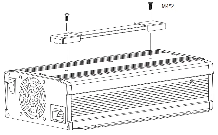
※ Carry handle (Optional accessory, battery charger and pull handle should be ordered seperately)
| MW’s Order No. | Item | Quantity | |
| DS-Carry Handle | 1 | Handle | 1 |
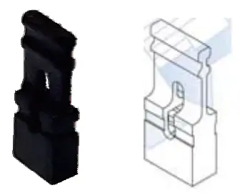
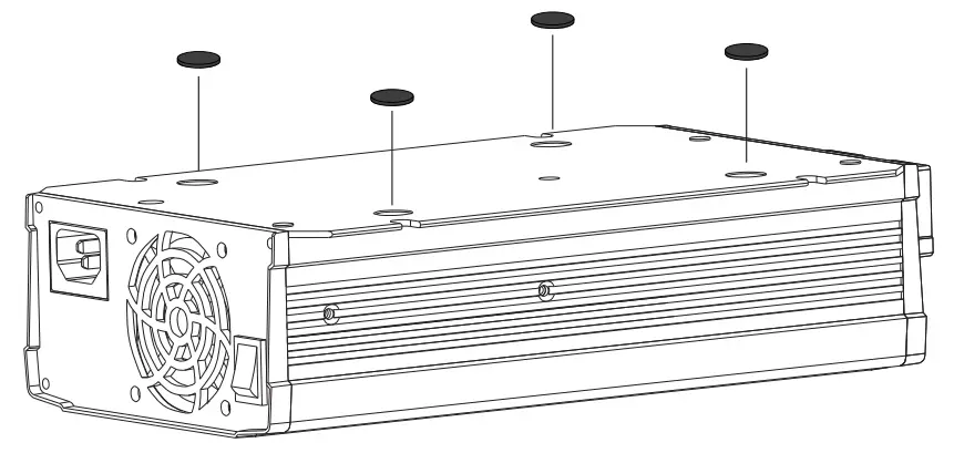
| 2 | Foot pad  | 4 | |
| 3 | Screw 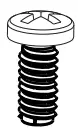 | 2 | |
- Handle
- Foot pad
INSTALLATION MANUAL
Please refer to : http://www.meanwell.com/manual.html
File Name:NPP-1200-SPEC 2021-11-29


