Fanvil i31S Video Door Phone Installation Guide
Package Contents
- Door Phone

- Connectors

- Quick Installation Guide

- Mounting Temlate
- RFIC Cards

- Screw and Wrench


Physical Specifications
| Device size | 223 x 130 x 74mm |
| Weight | 1800g |
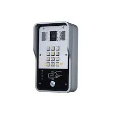
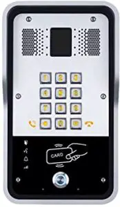
Front Panel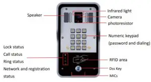
| Interface | Description |
| Camera | Get the video. |
| Infrared light & Photoresistor | The Compensate for lack of ambient light |
Speaker | The door phone has a built-in speaker for convenient communication and alert use. |
MIC | The door phone has a built-in microphone hidden in the pinhole located on the front panel |
| RFID Reader | Use RFID cards to unlock the door by touching RFID reader of device. |
Button Definition
| Button | Description |
DSS Key | Press the Button, calling or request to open the door. |
Numeric Keyboard | Input password to open the door or call. |
LED Definition
LED | Status | Description |
 Lock | Steady Blue | Door unlocking |
off | Door locking | |
 Call | Blinks per second | Hold |
Steady Blue | Call Hold | |
off | On Hook | |
 Ring | Steady Blue | Ringing |
off | On Hook | |
 Network & SIP Registration | Blinks per second | Network error |
off | Network is normal, SIP is not registered | |
Blinks every 3 seconds | SIP Registration failed | |
Steady Blue | SIP Registration succeeded |
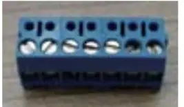
Port Definition
After removing the Back Panel of device, there are one terminal block connectors for power and lock control connection as shown in the picture below.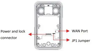
Network Connector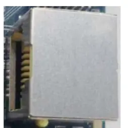
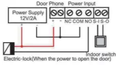
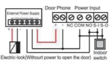
Power and Electric-lock Connector
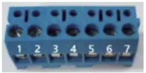
1 | 2 | 3 | 4 | 5 | 6 | 7 |
+DC12V | VSS | NC | COM | NO | S-IN | S-OUT |
12V DC Input | Electric-lock switch | Indoor switch | ||||
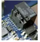
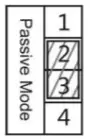
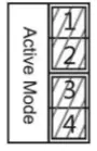
JP1 Jumper
There are two modes for power supply of electric-lock as shown in the picture below.
(The default is “Passive Mode ”).
Passive Mode:
When the electric-lock starting current is more than 12V/500mA, need to use the external
drive mode, the electric lock interface for short circuit output control.
Active Mode :
When the electric-lock starting current is less than 12V/500mA, can use the internal drive mode, the electric lock interface is 12V DC output.

- Jumper in passive mode

- Jumper in active mode
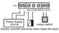
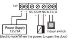
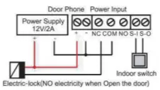
Wiring instructions
NO: Normally Open Contact
COM: Common Contact
NC: Normally Close Contact
Driving Mode | Electric-lock Mode | JP1 Jumper | Connections | ||
Active | Passive | No electricity when open | Electrify when open | ||
|
– |
– |
|  | ||
|
– |
– | 
|  | ||
|
– |
– | 
|  | ||
|
– |
– | 
|  | ||
|
– |
– | 
|  | ||

Installation
- Front

- Panel Main Part of Intercom

- Rain Shade

- Back Panel

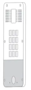
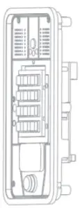
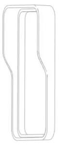
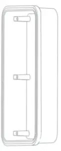
Figure 1 Three Major Parts of i31S
Step 1: Installation preparation
- Check the following contents:
- Hex wrench x 1
- RJ45 plugs x 2 (1 spare)
- TA5 x 40mm screws x 4
- 35mm screw anchors x4
- Tools that may be required:
- Hex wrench
- Phillips screwdriver (Ph2 or Ph3), hammer, RJ45 crimper
- Electric impact drill with an 6mm drill bit
Step 2: Drilling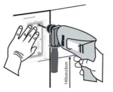
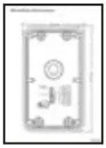
Figure 2 Wall Mounting
- Place the mounting template with dimensions on the surface of a wall in a desired flat position.
- Use an electric drill to drill the 4 holes marked on the mounting template. It is recommended to drill about 50mm deep. Remove the template when finishing drilling.
- Push or hammer screw anchors into the drilled holes.
Step 3: Removing hanging shell
- With L-shaped screwdriver, unpack the front panel as diagram (3) (Counter- lockwise) and (4)
 Figure 3
 Figure 4
 - After taking off the 6 conductive sponges in the plastic shell, use the cross screwdriver to remove the 6 screws on the plastic shell and remove the rain cover from the plastic shell. Then separate the plastic shell from the rear shell as diagram (5).

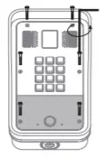 Figure 3
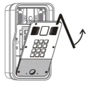 Figure 4
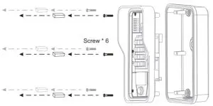
Figure 5
Step 4: Back panel fixing and cabling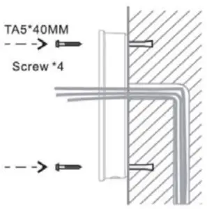
Figure 6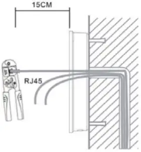
Figure 7
- Select the hole for cable supply, 15cm to 20cm cable length is recommended. Note: The direction of the cable hole on back panel is pointing down.
- With 4 TA5*40mm screws, tighten the back panel on the wall as diagram (6).
- Connect the cables of RJ45, power, and electric-lock to the motherboard socket as mentioned in connectors description (refer to Section 2).
- Test whether there is electricity by doing the following:
Press the # button for 3 seconds to get the IP address of intercom by voice. Input access password or press the indoor switch to check electric-lock installation.
Note: Do not proceed mounting until you have finished the electric checking.
Step 4: Mounting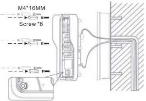
Figure 8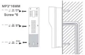
Figure 9
After locking the 6 screws into the corresponding position of the plastic housing, the 6 conductive sponges is loaded into a screw hole. As shown in Fig. 8, the rear shell is locked
Note: This sponge can enhance the ESD protection function of the product. Kindly suggest that it should not be ignored!
Push the front panel into the plastic frame, and tighten it with 6 screws as diagram (9)
Note: Make sure the screws have been tightened properly for better waterproof effect.
Searching Door Phone
There are two methods as shown below to search the device.
Method 1:
Open the iDoorPhone Network Scanner. Press the Refresh button to search the device and find the IP address.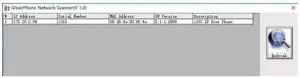
Method 2:
Press and hold the “#” key for 3 seconds and the door phone will report the IP address by voice.
In addition device provides the device surface DSS key operation to switch IP address acquisition mode: long press the DSS key for 10 seconds, to be issued by the speaker Beep, and then press the DSS key three times, the beep stops. Wait 10 seconds, after the success of the system automatically broadcast the current IP address.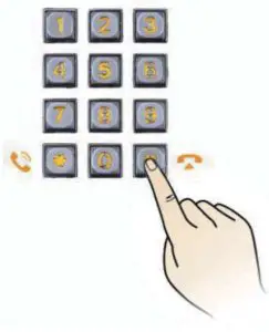
Default Setting | |
Default DHCP Client | Enable |
Static IP Address | 192.168.1.128 |
Default Web Port | 80 |
Default Login User Name | admin |
Default Login Password | admin |
Display IP address | Hold # for 3 seconds to display by voice |
Search Tools | iDoorPhone Network Scanner |
SIP Door Phone Setting
Step 1: Log in the door phone
Input IP address (e.g. http://192.168.1.149) into address bar of PC’s web browser.
The default user name and password are both admin.
Step 2: Add the SIP account.
Set SIP server address, port, user name, password and SIP user with assigned SIP account parameters.
Select “Activate”, and then click Apply to save this setting.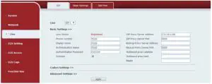
Step 3: Setting DSS key
Set the DSS key as shown below for a quick start. Click “Apply” to save this setting.
Type: Hot Key
Number 1: The DSS Key will dial to this Number 1.
Number 2: If Number 1 is unavailable, it will be forwarded to Number 2.
Line: Working line
Subtype: Speed dial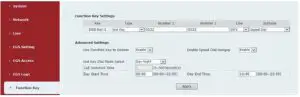
Step 4: Door Phone Setting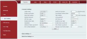
Door Unlocking Setting
Local
- Local Password
Step 1: Go to EGS Setting ї Features ї Set Local Password (The default is “6789”).
Step 2: Use the device’s Numeric Keyboard to input password and “#” key, and then the door will be unlocked.
- Private Access Code
Step 1: Go to EGS Access ї Access Rule ї set Access Code.
Step 2: Use the device’s Numeric Keyboard to input password and “#” key, and then the door will be unlocked.
Remote
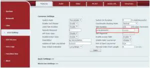
Remote Password
Step 1: Go to EGS Setting ї Features ї Set Remote Password (The default is “*”).
Step 2: To answer the call made by visitor via SIP phone, press the “*” key to unlock the door the visitor.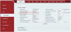
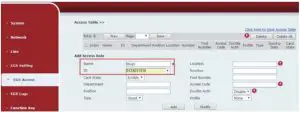
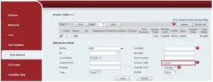
RFID Card
Step 1: Go to EGS Access ї Enter the Name and ID Number (Only Front 10 yards) ї Press Add to Access Table.
Step 2: Use pre assigned RFID cards to unlock the door by touching RFID area of device.