Video Door Phone
Quick Installation Guide
(1) Package Contents
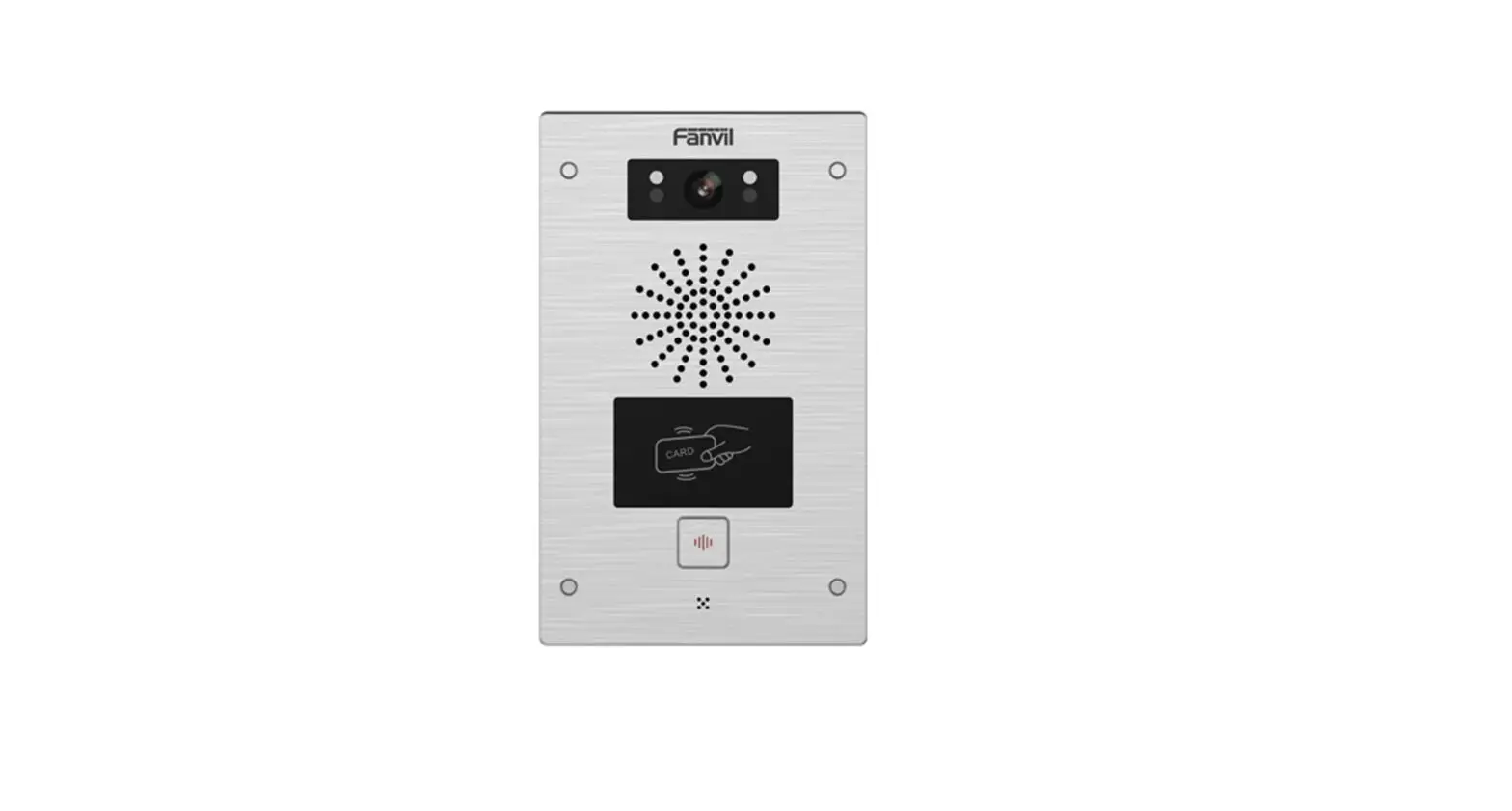
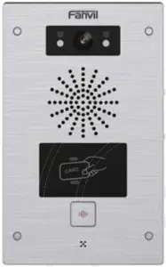
 i32V Video Door Phone
 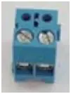 Connector
 Quick Installation Guide
 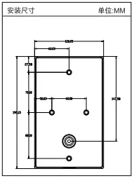 Mounting Template
 RFID Cards
  Screw and tool
(2) Physical specification
| Device size | 195 x 120 x 34 (mm) |
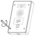
1) Panel
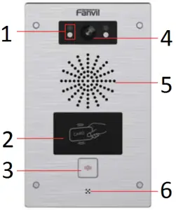
- IR LED
- RFID area
- DSS Key
- Camera
- Speaker
- MIC
2) Interface description
Open the rear case of the device, there is a row of terminal blocks for connecting the power supply, electric lock control, etc. The connection is as follows:
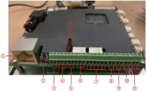
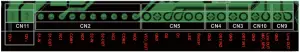
| Serial number | Description |
| 1 | Ethernet interface: standard RJ45 interface, 10/100M adaptive, it is recommended to use five or five types of network cable |
| 2 | Power interface: 12V/1A input left positive, right grounded |
| 3, 5 | Two sets of short-circuit input detection interfaces: for connecting switches, infrared probes, door magnets, vibration sensors and other input devices |
| 4, 6 | Two sets of short-circuit output control interface: used to control electric locks, alarms, etc. |
| 7 | Wiegand interface |
| 8, 9 | Two sets of door magnetic detection |
| 10 | Recording output interface: Mix the device and the sound of the far-end call. One is the recording signal line, and the other is the ground line (be sure to ground the line, otherwise there will be noise) |
| 11 | External active speaker interface: external active speakers for audio power amplification. One is the audio signal line, and the other is the ground line (be sure to ground the line, otherwise there will be noise) |
| 12 | JP1 jumper |
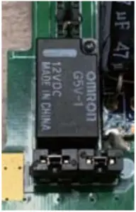
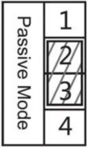
JP1 Jumper
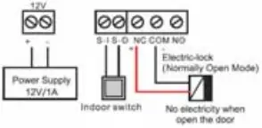
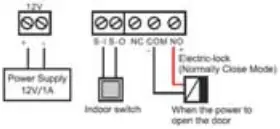
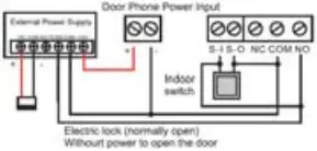
There are two modes for power supply of electric-lock as shown in the picture below.
(The default is “ Passive Mode: ”).
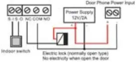
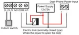
Passive Mode: When the electric-lock starting current is more than 12V/500mA, need to use the external drive mode, the electric lock interface for short circuit output control.
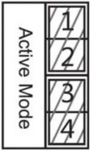
Active Mode : When the electric-lock starting current is less than 12V/500mA, can use the internal drive mode, the electric lock interface is 12V DC output.
3) Wiring instructions:
NO: Normally Open Contact
COM: Common Contact
NC: Normally Close Contact
Driving Mode | Electric-lock Mode | JP1 Jumper | Connections | ||
| Active | Passive | No electricity when open | Electrify when open | ||
√ | √ | |  | ||
√ | √ | |  | ||
√ | √ | |  | ||
√ | √ | |  | ||
√ | √ | |  | ||
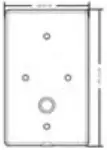
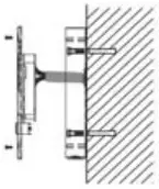
(3) Installation Diagram
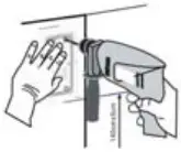
Wall-mounted:
1) Use built-in screw tool to remove the surface shell;
2) Based installation dimensions, mounting hole in the wall to draw, use an electric drill holes lay;
3) The white rubber plugged into the wall and the bottom fixed with screws to the wall;
4) After connecting the power cord and network cable, screw the surface shell fixed.
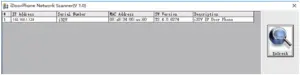
(4) Searching Door Phone
There are two methods as shown below to search the device.
Method 1:
Open the iDoorPhone Network Scanner. Press the Refresh button to search the device and find the IP address.
(Download address http://download.fanvil.com/tool/iDoorPhoneNetworkScanner.exe)
Method 2:
Long press DSS key for 10 seconds(after power-on for 30 seconds), and when the speaker beeps rapidly, press DSS key again quickly, the beeps stop, the intercom will report the IP address by itself.
In addition, device provides the device surface DSS key operation to switch IP address acquisition mode:
Long press the DSS key for 10 seconds, to be issued by the speaker Beep, and then press the DSS key three times, the beep stops. Wait 10 seconds, after the success of the system automatically broadcast the current IP address.
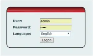
(5) IP Door Phone Setting
Step 1: Log in the door phone
Input IP address (e.g. http://192.168.1.128) into address bar of PC’s web browser.
The default user name and password are both admin.
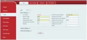
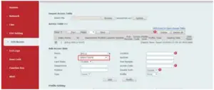
Step 2: Add the SIP account.
Set SIP server address, port, user name, password and SIP user with assigned SIP account parameters.
Select “Activate”, and then click Apply to save this setting.
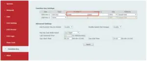
Step 3: Setting DSS key
Set the DSS key as shown below for a quick start. Click “Apply” to save this setting.
Type: Hot Key
Number 1: The DSS Key will dial to this Number 1.
Number 2: If Number 1 is unavailable, it will be forwarded to Number 2.
Line: Working line
Subtype: Speed dial
Step 4: Door Phone Setting
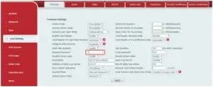
(6) Door Unlocking Setting
RFID Card
Step 1: Go to EGS Access → Enter the Name and ID Number (Only Front 10 yards) → Press Add to Access Table.
Step 2: Use pre assigned RFID cards to unlock the door by touching RFID area of device.
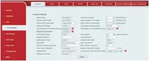
Remote Password
Step 1: Go to EGS Setting → Features → Set Remote Password (The default is “*”).
Step 2: To answer the call made by visitor via SIP phone, press the “*” key to unlock the door the visitor.
![]()
Fanvil Technology Co., Ltd
Add: 4F, Block A, Building 1#, GaoXinQi Hi-Tech Park (Phase-II),
67th District, Bao’An, Shenzhen, China P.C:518101
Tel:0755-2640-2199 Fax:0755-2640-2618 Email: [email protected]


