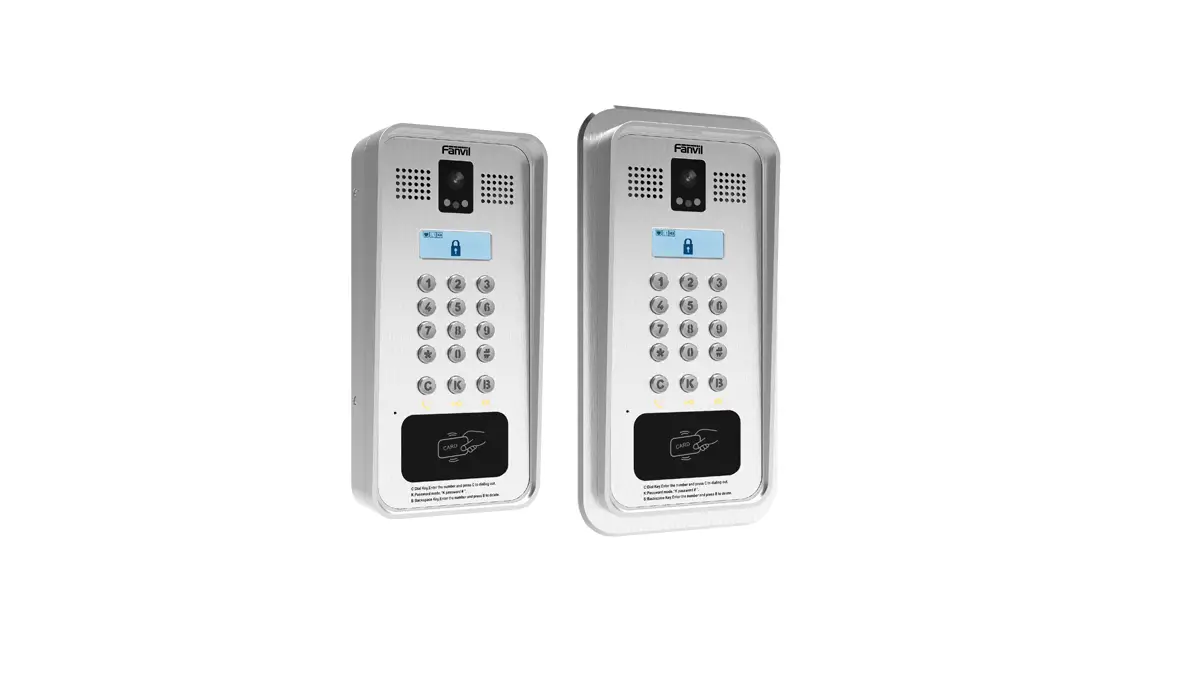
Video Door Phone
Quick Installation Guide
i33V i33VF
(1) Package Contents
 Video Door Phone
 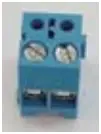 Connector
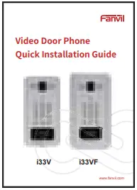 Quick Installation Guide
 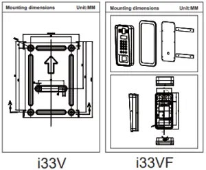 Mounting Template
 RFID Card
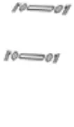
  Screw and Wrench
(2) Physical specification
| Device size | 295 x 142 x 62 (mm) |
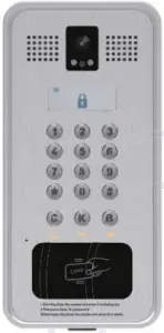
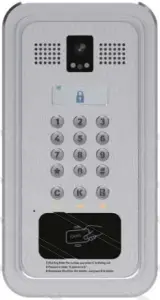
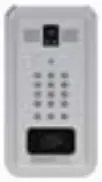
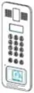
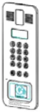
1) Panel
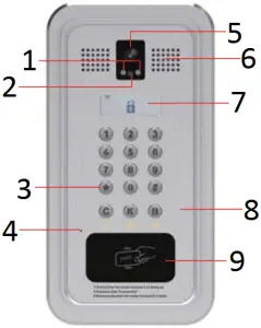
- IR LED
- Photoresistor
- Numeric keypad (password and dialing)
- MIC
- Camera
- Speaker
- LCD
- Function key
- RFID area
LCD
| LCD | Status | Description | Status | Description |
 | Connected to the Internet | Not connected to the Internet, flashing | ||
| SIP register success | SIP register fail, flashing | |||
| Connected to the TR069 | Not connected to the TR069, flashing | |||
| Lock off | Lock on | |||
| Fault prompt 1 (with error number) |  | Fault prompt 12 (?: flashing) | ||
| Call failed (no response) | Ringing | |||
| Dialing | Open the door |
Function Key
| Key | Description |
| C | Call Key, Enter the number and press C to dialing out. |
| K | Password mode,“K password # ” |
| B | Backspace Key, Enter the number and press B to delete |
| Numeric keypad | Input password or dialing |
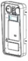
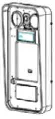
2) Interface description
Open the rear case of the device, there is a row of terminal blocks for connecting the power supply, electric lock control, etc. The connection is as follows:

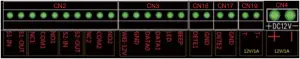
| Serial number | Description |
| 1 | Ethernet interface: standard RJ45 interface, 10/100M adaptive, it is recommended to use five or five types of network cable |
| 2, 4 | Two sets of short-circuit input detection interfaces: for connecting switches, infrared probes, door magnets, vibration sensors and other input devices |
| 3 | Short circuit output 1: drive / short circuit output configurable |
| 5 | Short-circuit output 2: corresponding to the short-circuit input interface, login device webpage setting, can be connected to the electric lock, alarm device, etc. |
| 6 | Wiegand interface |
| 7, 8 | Two sets of door magnetic detection |
| 9 | Temperature control power interface: 12V/1A input |
| 10 | Power interface: 12V/1A input |
| 11 | JP1 jumper |
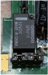
JP1 Jumper
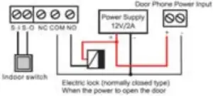
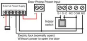
There are two modes for power supply of electric-lock as shown in the picture below.
(The default is “Passive Mode:”).
Passive Mode: When the electric-lock starting current is more than 12V/500mA, need to use the external drive mode, the electric lock interface for short circuit output control.
Active Mode : When the electric-lock starting current is less than 12V/500mA, can use the internal drive mode, the electric lock interface is 12V DC output.
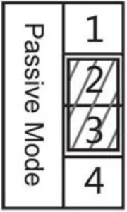
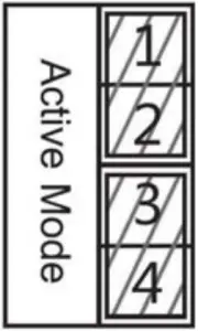
Jumper in Passive Mode Jumper in Active Mode
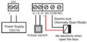
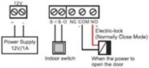
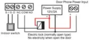
3) Wiring instructions:
NO: Normally Open Contact
COM: Common Contact
NC: Normally Close Contact
Driving Mode | Electric-lock Mode | JP1 Jumper | Connections | ||
| Active | Passive | No electricity when open | Electrify when open | ||
√ | √ | |  | ||
√ | √ | |  | ||
√ | √ | |  | ||
√ | √ | |  | ||
√ | √ | |  | ||
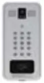
(3) Installation
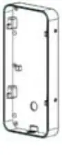
Panel Main Body Back Shell Wall Bracket
Figure 3-1 Four Major Parts of i33V
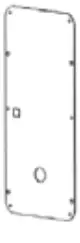
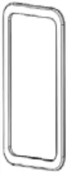
Panel Main Body Bottom Plate Middle frame Stand
Figure 3-2 Five Major Parts of i33VF
Step 1: Installation preparation
A. Check the following contents:
• Hex wrench x 1
• TA5 x 40mm screws x 4
• 35mm screw anchors x4
B. Tools that may be required:
• Hex wrench
• Phillips screwdriver, hammer, RJ45 crimper
• Electric impact drill with an 8mm drill bit
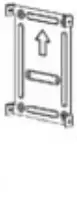
Step 2: Drilling
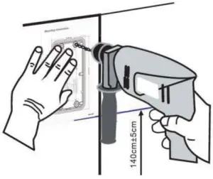
Figure 3-3 Wall Mounting / Built-in
A. Place the mounting template with dimensions on the surface of a wall in a desired flat position.
B. Use an electric drill to drill the 4 holes marked on the mounting template. It is recommended to drill about 50mm deep. Remove the template when finishing drilling.
C. Push or hammer screw anchors into the drilled holes.
Step 3: Removing hanging shell
• i33V
A. Use a screwdriver to remove the 4 screws on both sides and separate the rear case from the wall bracket, as shown in Figure 3-4.
B. Use a screwdriver to remove the 6 screws on the back of the rear case and separate the rear case., as shown in Figure 3-5.

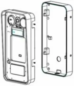
Figure 3-4 Figure 3-5
• i33VF
Use a screwdriver to remove the 6 screws on the back of the rear case and separate the rear case, as shown in Figure 3-6.
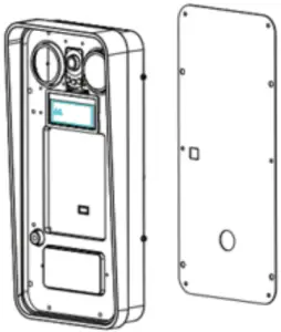
Figure 3-6
Step 4: Install the wall bracket, wiring and casing
• i33V
A. Align the screw holes of the wall bracket with the holes in the wall and fix them to the wall with the TA5 x40mm screws, as shown in Figure 3-7.
B. Pass all the wires through the silicone plug in the middle of the bottom case. All lines should be reserved for 15~20CM length, as shown in Figure 3-8.
Note: The outlet hole of the bottom case faces down.
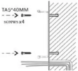
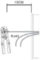
Figure 3-7 Figure 3-8
C. Connect the cables of RJ45, power, and electric-lock to the motherboard socket as mentioned in connectors description (refer to Section 2).
D. Connect the terminal of the wired cable to the motherboard socket (refer to Section 2).
E. Test whether there is electricity by doing the following:
Press the # button for 3 seconds to get the IP address of intercom by voice.
Input access password or press the indoor switch to check electric-lock installation.
Note: Do not proceed mounting until you have finished the electric checking.
F. Lock the rear case to the main body by locking the 6 screws previously removed into the corresponding position of the rear case.
G. Lock the rear case and the wall bracket by locking the 4 screws previously removed into the corresponding positions on both sides.
H. To ensure a waterproof seal, tighten the screws.
• i33VF
A. Pass all the wires through the silicone plug in the middle of the bottom case. All lines should be reserved for 15~20CM length, as shown in Figure 3-8.
Note: The outlet hole of the bottom case faces down.
B. Connect the cables of RJ45, power, and electric-lock to the motherboard socket as mentioned in connectors description (refer to Section 2).
C. Connect the terminal of the wired cable to the motherboard socket (refer to Section 2).
D. Test whether there is electricity by doing the following:
Press the # button for 3 seconds to get the IP address of intercom by voice.
Input access password or press the indoor switch to check electric-lock installation.
Note: Do not proceed mounting until you have finished the electric checking.
E. Lock the bottom plate to the main body by locking the 6 screws previously removed into the corresponding position on the bottom plate
F. Put the decorative piece from the back to the front, pay attention to the front and back of the decorative piece, as shown in Figure 3-9.
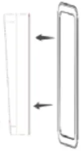
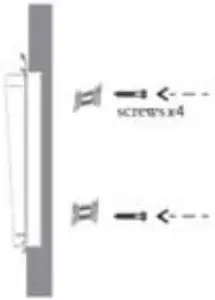
Figure 3-9 Figure 3-10
G. Put the installed machine into the groove in the door, tighten it from the back of the door with 4 screws, and fix the machine with the decorative piece and bracket, as shown in Figure 3-10.
H. To ensure a waterproof seal, tighten the screws.
(4) Searching Door Phone
There are two methods as shown below to search the device.
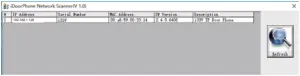
Method 1:
Open the iDoorPhone Network Scanner. Press the Refresh button to search the device and find the IP address.
(Download address http://download.fanvil.com/tool/iDoorPhoneNetworkScanner.exe)
Method 2:
Long press DSS key for 10 seconds(after power-on for 30 seconds), and when the speaker beeps rapidly, press DSS key again quickly, the beeps stop, the intercom will report the IP address by itself.
In addition, device provides the device surface DSS key operation to switch IP address acquisition mode:
Long press the DSS key for 10 seconds, to be issued by the speaker Beep, and then press the DSS key three times, the beep stops. Wait 10 seconds, after the success of the system automatically broadcast the current IP address.
(5) IP Door Setting
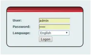
Step 1: Log in the door phone
Input IP address (e.g. http://192.168.1.128) into address bar of PC’s web browser. The default user name and password are both admin.
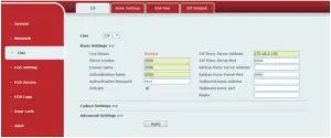
Step 2: Add the SIP account.
Set SIP server address, port, user name, password and SIP user with assigned SIP account parameters.
Select “Activate”, and then click Apply to save this setting.
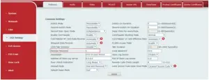
Step 3: Door Phone Setting
(6) Door Unlocking Setting
Local
1) Local Password
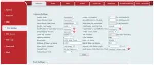
Step 1: Go to EGS Setting → Features → Set Local Password (The default is “6789”).
Step 2: Use the device’s Numeric Keyboard to input password and “#” key, and then the door will be unlocked.
2) Private Access Code
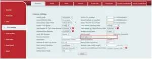
Step 1: Go to EGS Access → Access Rule → Set Access Code.
Step 2: Use the device’s Numeric Keyboard to press K and enter the Access Code and press # to end, the door will be unlocked.
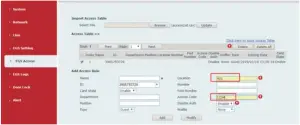
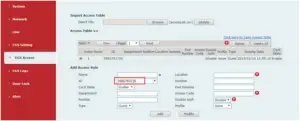
RFID Card
Step 1: Go to EGS Access → Enter the Name and ID Number (Only Front 10 yards) → Press Add to Access Table.
Step 2: Use pre assigned RFID cards to unlock the door by touching RFID area of device.
Remote Password
Step 1: Go to EGS Setting → Features → Set Remote Password (The default is “*”).
Step 2: To answer the call made by visitor via SIP phone, press the “*” key to unlock the door the visitor.
Fanvil Technology Co., Ltd
Add: 4F, Block A, Building 1#, GaoXinQi Hi-Tech Park (Phase-II),
67th District, Bao’An, Shenzhen, China P.C:518101
Tel:0755-2640-2199 Fax:0755-2640-2618 Email:[email protected]


