MARSON MT1 2D Scan Engine
INTRODUCTION
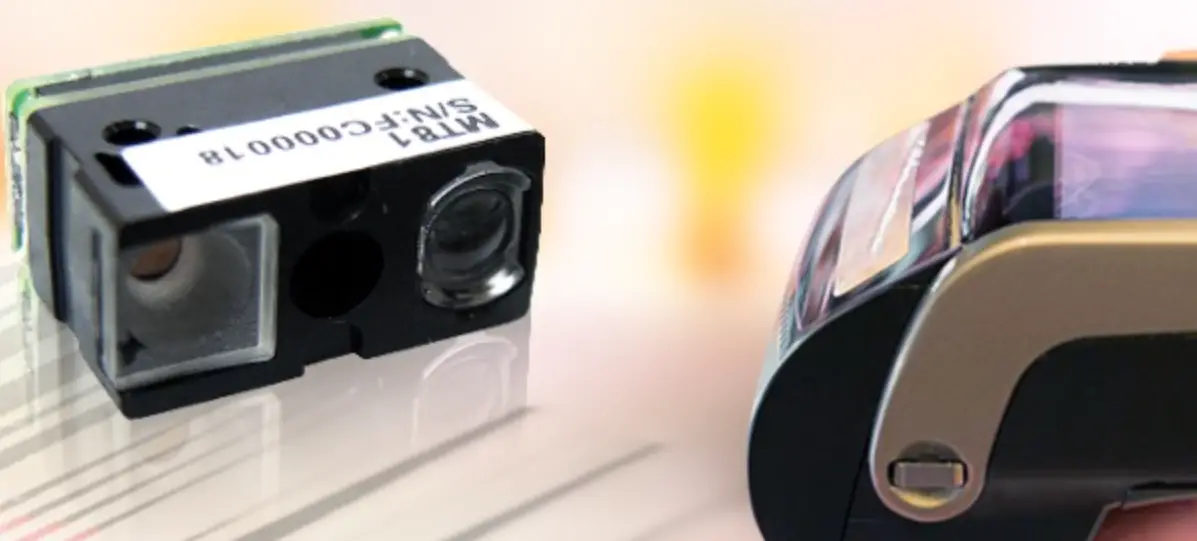
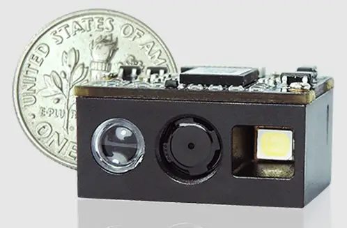
MT1 One-piece Compact 2D Scan Engine provides snappy scanning performance at a competitive cost and compact form factor. With its all-in-one design, MT1 2D scan engine can be easily integrated with specific applications such as access control, lottery kiosk and consumer electronics.
The MT1 2D Scan Engine consists of 1 illumination LED, 1 aimer LED and a
high-quality image sensor with a microprocessor that contains powerful firmware to control all aspects of operations and enable communication with the host system over the standard set of communication interfaces.
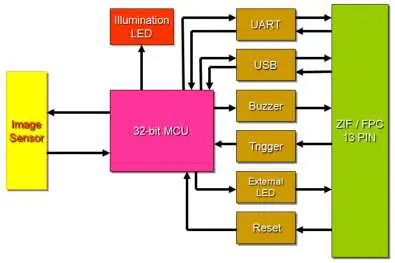
Two interfaces, UART & USB, are available. UART interface communicates with the host system over TTL-level RS232 communication; USB interface emulates a USB HID Keyboard or Virtual COM port device and communicates with the host system over USB.
Block Diagram
Electric Interface
Pin Assignment
(Back View of MT1)
Contact points of connector are on the inside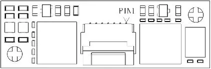
| Pin# | Definition | I/O | Description | Schematic Example |
| 1 | GND | ———— | Power and signal ground. | 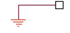 |
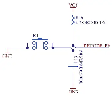
| 2 | nTRIG | Input | High: Stop Scanning Low: Start Scanning |
Once nTRIG pin is pull low for more than 5ms, the scanning operation starts until a barcode is successfully decoded or the nTRIG pin is pull high. To proceed to the next scanning operation, pull high first and pull low again. A minimum of 50ms interval is recommended between two trigger signals. |
| 3 | nRST | Input | Keep level low for at least 100us to reset the scan engine. | If the pin is not in use, leave it unconnected. |
| 4 | LED | Output | When scanning is successful (Good Read), it outputs a high-level pulse, whose load capacity is limited and not enough to driver LED directly. A supporting LED drive circuit is required. | 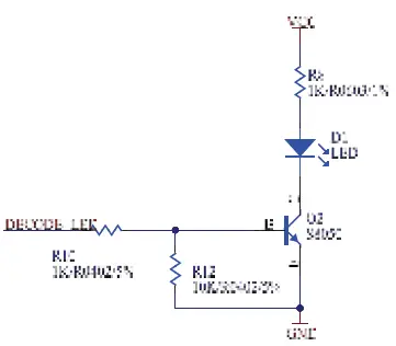 |
| 5 | Buzzer | Output | Active High: it indicates the status of Power-Up or a successful barcode decode. PWM controlled signal can be used to drive an external buzzer for a successful barcode decode (Good Read). | 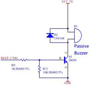 |
| 6 | EXT LED CTRL | Output | External LED illumination control signal. | 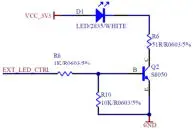 If the pin is not in use, leave it unconnected. If the pin is not in use, leave it unconnected. |
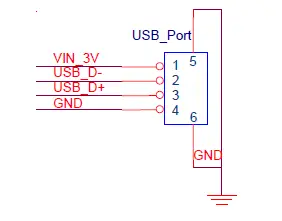
| 7 | USB_D+ | Bidirectional | USB Differential Signal Transmission (USB D+) | 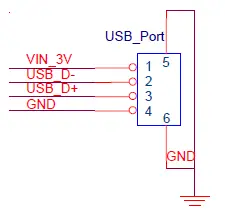 USB_Port VIN_3V 1 5 USB_D- 2 USB_D+ 3 GND 46 GND |
| 8 | USB_D- | Bidirectional | USB Differential Signal Transmission (USB D-) |
USB_D- 2 USB_D+ 3 GND 4 6 GND |
| 9 | UART_TX | Output | UART TTL data output. |
|
| 10 | UART_RX | Input | UART TTL data input. |
|
| 11 | GND | ———— | Power and signal ground. | |
| 12 | VCC | ———— | Supply voltage input. Must always be connected to 3.3V power supply. |  |
| 13 | VCC | ———— | Supply voltage input. Must always be connected to 3.3V power supply. | |
 USB_Port VIN_3V
Electric Characteristics
- Operating Voltage Ta=25°C
| Symbol | Ratings | Min | Typical | Max | Unit |
| VDD | Power supply | — | 3.3 | — |
V |
| VIL | Input low level | — | — | 0.8 | |
| VIH | Input high level | 2 | — | — | |
| VOL | Output low level | — | — | 0.4 | |
| VOH | Output high level | 2.5 | — | — |
Operating Current
Ta=25°C, VDD=3.3V
| Ratings | Max | Unit |
| Standby Current | 15 | mA |
| Working Current | 200 |
SPECIFICATIONS
Technical specifications
| Optic & Performance | |
| Light Source | White LED |
| Aiming | Visible red LED |
| Sensor | 640 x 480 pixels |
| Resolution | 3mil/ 0.075mm (Code 39) |
| Field of View | Horizontal 43° Vertical 33° |
| Scan Angle | Pitch Angle ±55° Skew Angle ±55° Roll Angle 360° |
| Print Contrast Ratio | 10% |
| Width of Field | 176mm (13Mil Code39) |
| Typical Depth Of Field | 5 Mil Code39: 42 ~ 204mm |
| 13 Mil UPC/EAN: 45 ~ 350mm | |
| 15 Mil QR Code: 28 ~ 246mm | |
| 6.67 Mil PDF417: 46 ~ 152mm | |
| 10 Mil Data Matrix: 37 ~ 150mm | |
| Physical Characteristics | |
| Dimension | W21.5 x L9 x H6.7 mm |
| Weight | 1.25g |
| Color | Black |
| Material | Plastic |
| Connector | 13pin ZIF (pitch=0.3mm) |
| Cable | 13pin to 12pin flex cable (pitch=0.5mm) |
| Electrical | |
| Operation Voltage | 3.3VDC ± 5% |
| Working Current | < 200 mA |
| Standby Current | < 15 mA |
| Idle Current (Sleep Mode) | Typ. 2.7mA |
| Connectivity | |
| Interface | UART (TTL-level RS232) |
| USB (HID Keyboard) | |
| USB (Virtual COM) | |
| User Environment | |
| Operating Temperature | -20°C ~ 60°C |
| Storage Temperature | -40°C ~ 70°C |
| Humidity | 5% ~ 95%RH (Non-condensing) |
| Drop Durability | 1.5M |
| Ambient Light | 100,000 Lux (Sunlight) |
| 1D Symbologies | UPC-A / UPC-E EAN-8 / EAN-13 ISBN / ISSN Codabar Code 11 Code 39 Code 32 Code 93 Code 128 Interleaved 2 of 5 Matrix 2 of 5 Industrial 2 of 5 Standard 2 of 5 Plessey MSI Plessey Febraban Composite GS1 Databar |
| 2D Symbologies | QR Code Micro QR Code PDF417 MicroPDF417 Data Matrix Aztec MaxiCode HanXin DotCode |
| Regulatory | |
| ESD | Functional after 4KV contact, 8KV air discharge |
| (It requires housing that is designed for ESD protection and stray from electric fields.) | |
| EMC | TBA |
| Safety Approval | TBA |
| Environmental | RoHS 2.0 |
Interface
UART Interface
- Below are default communication protocols: Baud rate: 9600
- Data Bits: 8
- Parity: None
- Stop Bit: 1
- Handshaking: None
- Flow Control Timeout: None
- ACK/NAK: OFF
- BCC: OFF
Interface Configuration Barcode:
 UART
UART
USB HIID Interface
Interface Configuration Barcode:
 USB HID
USB VCP Interface
Interface Configuration Barcode:
 USB VCP
Operation Method
- At power-up, the MT1 sends the Power-Up signals over Buzzer and LED pins as an indication that the MT1 enters Standby Mode and is ready for operation.
- Once the MT1 triggered by either hardware or software method, MT1 will emit a beam of light which is aligned with the sensor’s field of view.
- The area image sensor captures the image of barcode and produces an analog waveform, which is sampled and analyzed by the decoder firmware running on the MT1.
- Upon a successful barcode decoded, the MT1 turns off the illumination LEDs, sending the Good Read signals over Buzzer and LED pins and transmitting the decoded data to the host.
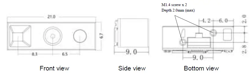
Mechanical Dimension
(Unit = mm, Tolerance = ±0.2mm)
Connector Specification
MT1 is built with a 13-pin pitch 0.3mm FPC connector. The recommended Model No. of 13-pin connector is FH35C-13S-0.3SHW(50)
When the 13-pin to 12-pin FPC cable (shipped with MT1 by default) is used, the recommended Model No. of 12-pin pitch 0.5mm FPC connector on the host side is FH34SRJ-12S-0.5SH(50), with pin assignment below:
| Pin# | Definition | I/O | Description |
| 1 | NC | ———— | Floating |
| 2 | VCC | ———— | 3.3V power supply. |
| 3 | GND | ———— | Power and signal ground. |
| 4 | UART_TX | Output | UART TTL data output. |
| 5 | UART_RX | Input | UART TTL data input. |
| 6 | USB_D- | Bidirectional | USB D- signal |
| 7 | USB_D+ | Bidirectional | USB D+ signal |
| 8 | NC | ———— | Floating |
| 9 | Buzzer | Input | Buzzer input |
| 10 | LED | Input | Good read LED input |
| 11 | nRST | Output | Reset signal output |
| 12 | nTRIG | Output | Trigger signal output |
INSTALTION
The scan engine is designed specifically for integration into customer’s housing for OEM applications. However, the scan engine’s performance will be adversely affected or permanently damaged when mounted into an unsuitable enclosure.
Warning: The limited warranty is void if the following recommendations are not adhered to when mounting the scan engine.
Electrosstatic Discharge Cautions
All scan engines are shipped in ESD protective packaging due to the sensitive nature of the exposed electrical components.
- ALWAYS use grounding wrist straps and a grounded work area when unpacking and handling the scan engine.
- Mount the scan engine in a housing that is designed for ESD protection and stray electric fields.
Installation Recommended
When securing the scan engine by utilizing the machine screws:
- Leave sufficient space to accommodate the maximum size of the scan engine.
- Do not exceed 1kg-cm (0.86 lb-in) of torque when securing the scan engine to the host.
- Use safe ESD practices when handling and mounting the scan engine.
- Do not enclose the scan engine with thermal insulation material. Failure of heat dissipation may deteriorate the scan engine’s performance.
Installation Orientation
 Two M1.4 screw holes (max depth 2mm) are available at the bottom of MT1. When the screw holes are facing downwards, MT1’s appearance should be identical to above picture.
Window Materials
Following are descriptions of three popular window materials:
- Poly-methyl Methacrylic (PMMA)
- Allyl Diglycol Carbonate (ADC)
- Chemically tempered float glass
Cell Cast Acrylic (ASTM: PMMA)
Cell cast Acrylic, or Poly-methyl Methacrylic is fabricated by casting acrylic between two precision sheet of glass. This material has very good optical quality, but is relatively soft and susceptible to attack by chemicals, mechanical stress and UV light. It is strongly recommended to have acrylic hard-coated with Polysiloxane to provide abrasion resistance and protection from environmental factors. Acrylic can be laser-cut into odd shapes and ultrasonically welded.
Cell Cast ADC, Allyl Diglycol Carbonate (ASTM: ADC)
Also known as CR-39TM, ADC, a thermal setting plastic widely used for plastic eyeglasses, has excellent chemical and environmental resistance. It also has an inherently moderate surface hardness and therefore does not require hard-coating. This material cannot be ultrasonically welded.
Chemically Tempered Float Glass
Glass is a hard material which provides excellent scratch and abrasion resistance. However, un-annealed glass is brittle. Increased flexibility strength with minimal optical distortion requires chemical tempering. Glass cannot be ultrasonically welded and is difficult to cut into odd shapes.
| Property | Description |
| Spectral Transmission | 85% minimum from 635 to 690 nanometers |
| Thickness | < 1 mm |
| Coating | Both sides to be anti-reflection coated to provide 1% maximum reflectivity from 635 to 690 nanometers at nominal window tilt angle. An anti-reflection coating can reduce the light that is reflected back to the host case. Coatings will comply with the hardness adherence requirements of MIL-M-13508. |
Window Placement
MT1 Side View 
The distance between window and front of MT1 should not exceed L=0.5mm The thickness of the window should not exceed 1mm
Window Size
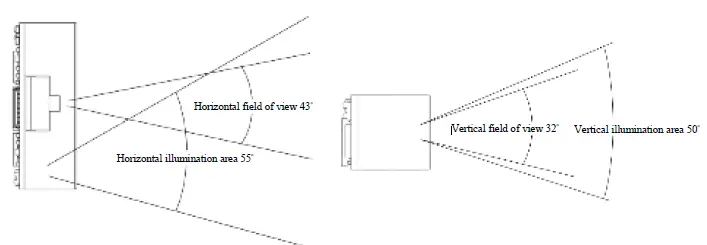 The window size should ensure that field of view is not blocked, and the illumination area should not be blocked as well. For the size of window, please refer to above diagram of each optical area.
Window Care
In the aspect of window, the performance of MT1 will be reduced due to any kind of scratch. Thus, reducing the damage of window, there are few things have to be noticed.
- Avoid touching the window as much as possible.
- When cleaning the window surface, please use non-abrasive cleaning cloth, and then gently wipe the host window with the cloth that is already sprayed with glass cleaner.
REGULATIONS
The MT1 scan engine conforms to the following regulations:
- Electromagnetic Compliance – TBA
- Electromagnetic Interference – TBA
- Photobiological Safety – TBA
- Environmental Regulations – RoHS 2.0
DEVELOPMENT KIT
MB130 Demo Kit (P/N: 11D0-A020000) includes an MB130 Multi I/O Board (P/N: 9014-3100000) and a micro USB cable. MB130 Multi I/O Board serves as an interface board for MT1 and accelerates the testing and integration with the host system. Please contact your sales representative for ordering information.
MB130 Multi I/O Board (P/N: 9014-3100000) 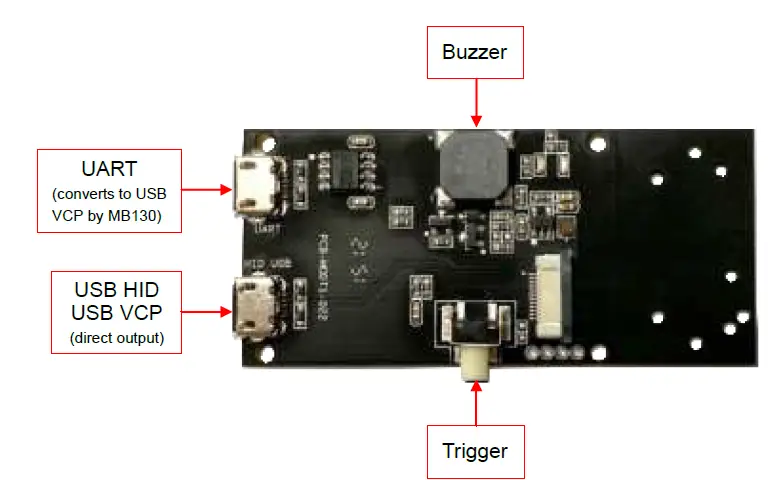
PACKAGING
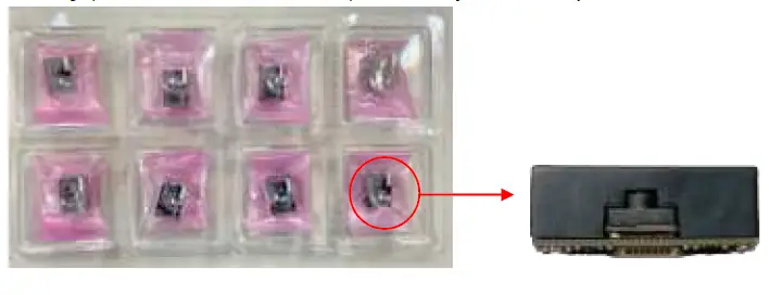
- Tray (size: 24.7 x 13.7 x 2.7cm): Each tray contains 8pcs of MT1.

- Box (size: 25 x 14 x 3.3cm): Each Box contains 1pc of tray, or 8pcs of MT1.

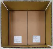
- Carton (size: 30 x 27 x 28cm): Each Carton contains 16pcs of boxes, or 128pcs of MT1.

VERSION HISTORY
| Rev. | Date | Description | Issued | Checked |
| 0.1 | 2022.09.12 | Initial Release | Shaw | Ming |
| 0.2 | 2022.09.22 | Updated Pin Assignment | Shaw | Ming |
Marson Technology Co., Ltd.
9F., 108-3, Minquan Rd., Xindian Dist., New Taipei City, Taiwan
TEL: 886-2-2218-1633
FAX: 886-2-2218-6638
E-mail: [email protected]
Web: www.marson.com.tw


