aerauliqa AD1400B High Volume Axial Fans
GENERAL INFORMATION
Carefully read the instructions contained in this manual.
This Specific Manual MUST be read in conjunction with the “Installation, Operation and Maintanance General Manual”.
Note: store the manual for future reference. We reserve the right to improve and make changes to the manual, products and accessories without any obligation to update previous productions and manuals.
The installation and service of the unit and complete ventilation system must be performed by an authorized installer and in accordance with local rules and regulationid.
PRECAUTIONS
In addition to the precautions indicated in the “Installation, Operation and Maintenance General Manual” special attention should be paid to the following warning notes:
- The fan must be installed at a height of not less than 2.7m from the floor below. Installation at a lower height is considered “improper use”. In case of “improper use” the manufacturer declines all responsibility for any damage that may be caused to persons or property, and any warranty will be considered invalid.
RECOMMENDED BOLT TORQUE FOR COARSE THREADED METRIC STEEL BOLTS TE-TCEI GRADE 8.
| Dimensions | M6 | M8 | M10 | M12 | M14 | M16 |
| Nm | 9,5 | 23 | 46 | 79 | 127 | 198 |
Table 1 Use the values shown in the table to tighten all the screws.
- Check/inspect and eventually retighten all the fixing annually.
- Fans should not operate in case of strong wind (≥ 6m/s).
The installer and the building owner are responsible to ensure the safety of the fan mounting system and that the fan installation is correct, in compliance with any national and local regulations.
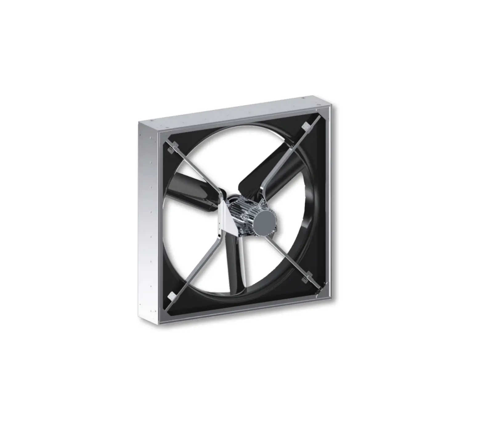
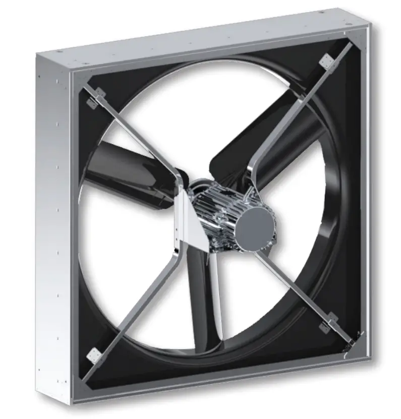
TYPE
Ceiling fan with EC brushless motor suitable for wall installation or suspended at ceiling, designed for industrial, civil and zootechnical applications, where high performances are required.
MAIN FEATURES
- EC Brushless motor 220-277 Vac, 1ph, 50/60Hz, IP55
- Max temperature +50°C
- Speed controllable
- Suitable for S1 continuous service
- Embedded electronic system
- Gearless for silent operation and maintenance free
- Simplified electrical wiring connection: pre-wired cables
- Strong and robust design and manufacturing (galvanised steel)
- High efficient unit (energy saving EC motor and airfoil impeller)
DATA @400Vac, 50Hz
Model | Fan diam. | Max speed rotation | Max absorbed power | Max Thrust | Max airflow AMCA 230-15 | Max airflow AMCA 230-99 | ||||
| r/min | kW | N | cfm | m3/h | SPI(1) W/(m3/s) | cfm | m3/h | SPI(1) W/(m3/s) | ||
AD1400B | 1170 | 500 | 1,40 | 105 | 20551 | 34917 | 144,3 | 29064 | 49380 | 102,1 |
(1) max. absorbed power / max. airflow
DIMENSIONS AND CLEARANCES
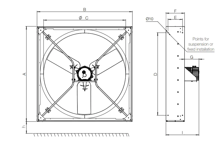
Model | A | B | C | D | E | F | G | I | h (min)* | Weight |
| mm | mm | mm | mm | mm | mm | mm | mm | mm | kg | |
| AD1400B | 1382 | 1382 | 1189 | 1200 | 210 | 270 | 208 | 478 | 2700 | 52 |
*ATTENTION: The fan must be installed at a height of not less than 2.7m from the floor below
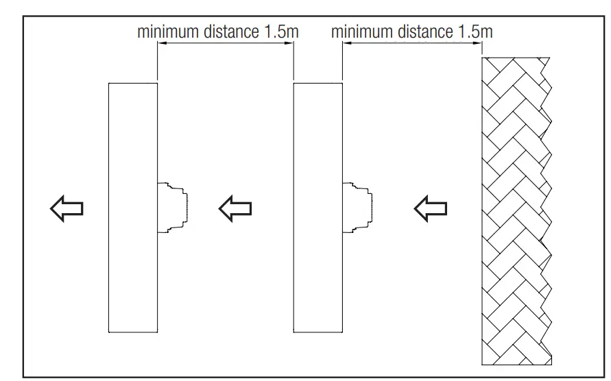
ATTENTION: A minimum air space in front and behind the fan of 1.5m is required (from wall or similar obstacle and between each fan in case of in-line installation of multiple units)
COMPONENTS
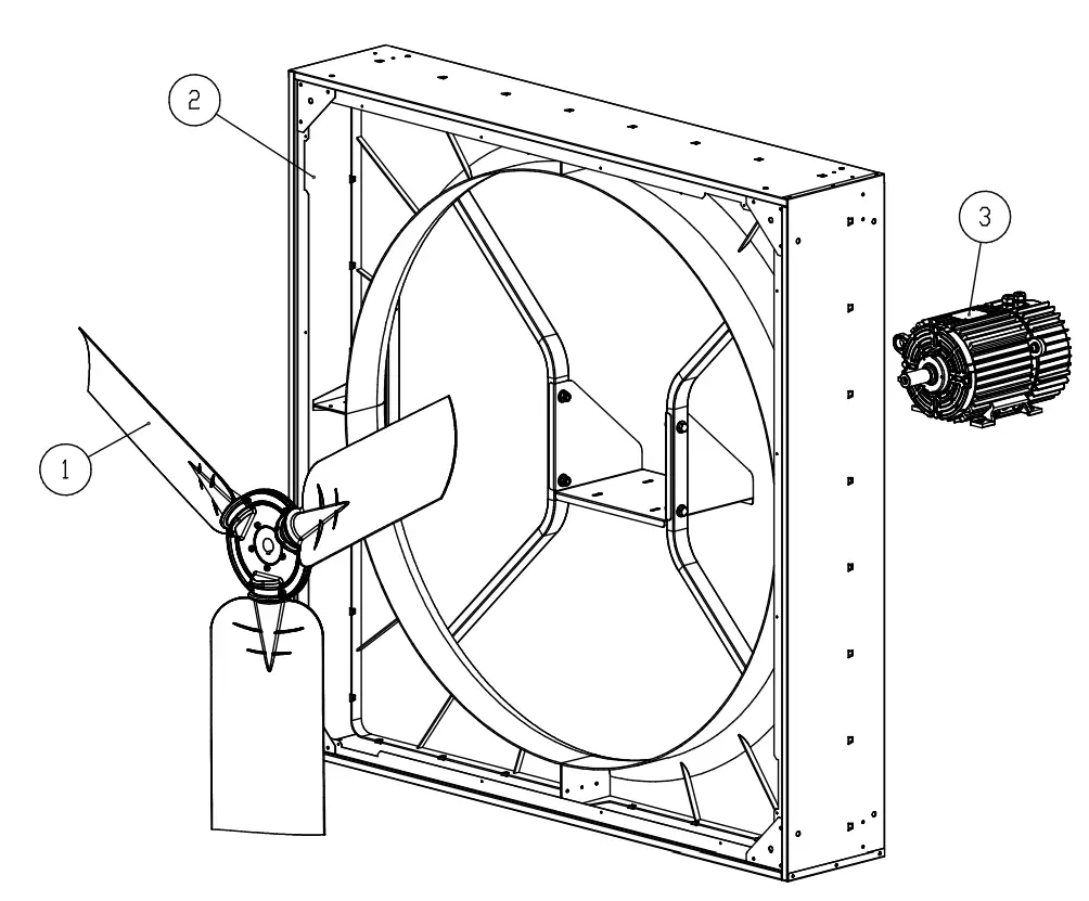
Pos. | Description | Q.ty |
| 1 | Impeller | 1 |
2 | Casing | 1 |
| 3 | Motor | 1 |
INSTALLATION
ATTENTION Make sure that the main supply to the unit is disconnected before performing any installation, service, maintenance or electrical work!
The fan must be installed at a height of not less than 2.7m from the floor below.
The fan must be installed with sufficient surrounding space for assembly/disassembly, cleaning and maintenance.
The fan can be wall installed or suspended at ceiling.
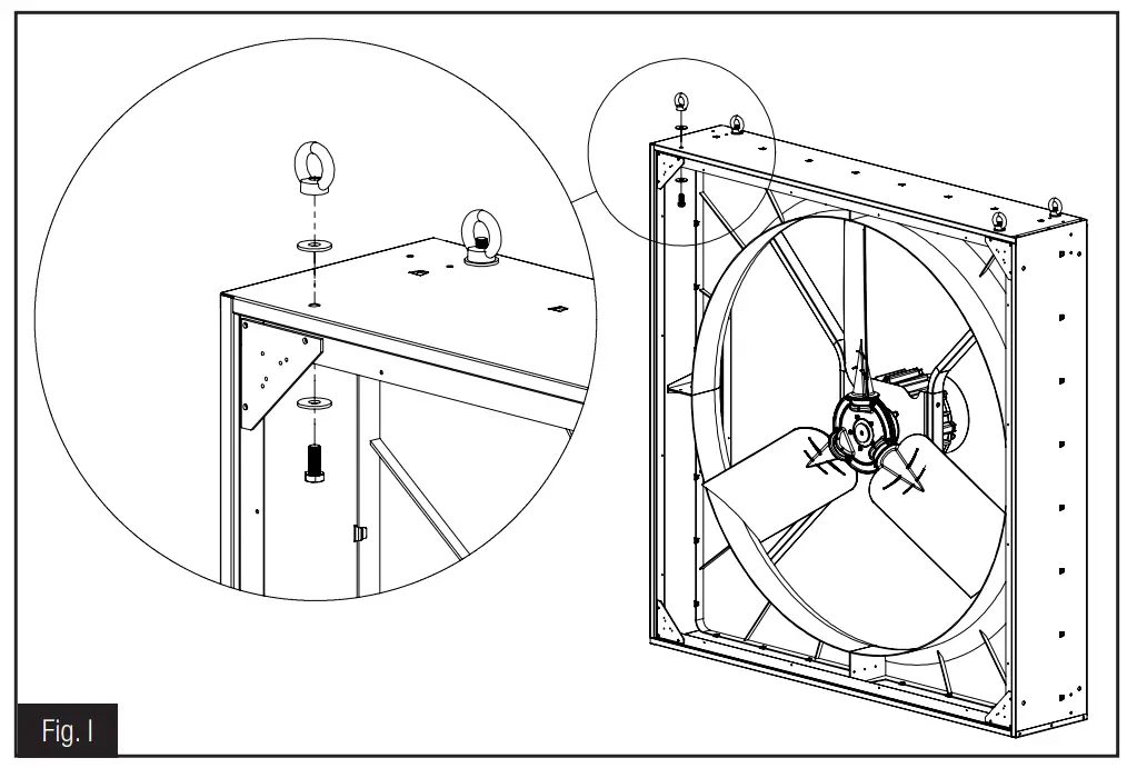
ATTENTION: For suspended installation pay attention to the following indications.
Eyebolts are provided for units which are to be suspended, as per Fig.1: the weight has to be evenly distributed.
Avoid spinning of the unit out of control. Provide suitable chains or ropes. It is recommended to use a suspension means with a workload of at least 2 kN and breaking load of at least 5 kN.
In the case of fixed installation, provide a mechanical expansion anchor intended for use in solid concrete, or metric screws for use in metal or wooden structures using the entire available diameter of the holes in the fixing points.
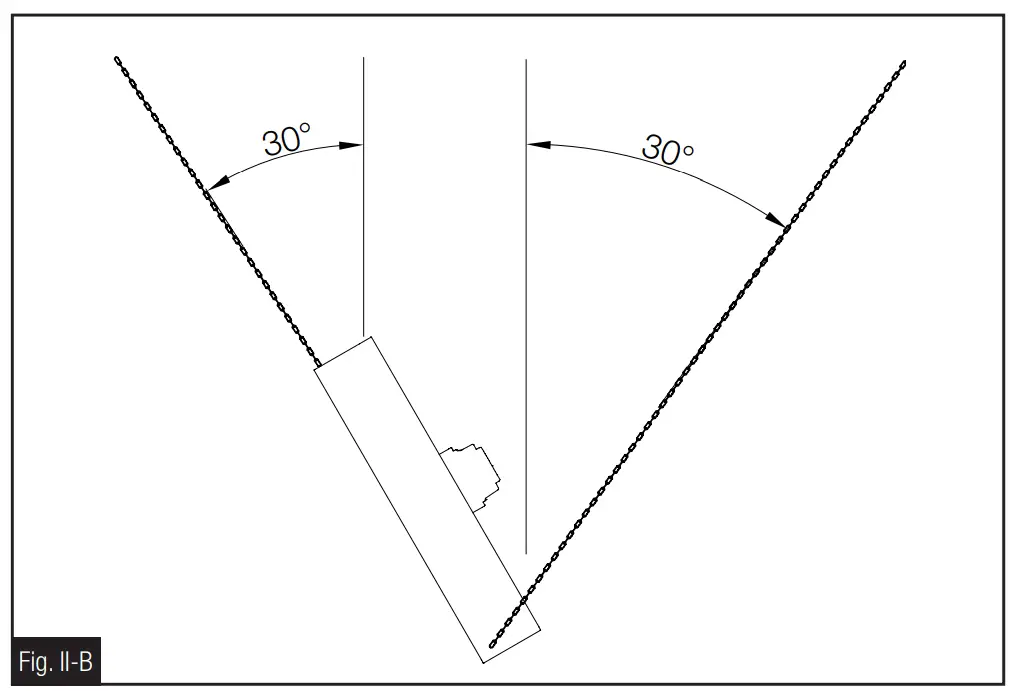
The suspension chains must be installed at an angle of approx. 45° as shown in Fig. I-A. The fan will naturally tilt back under operation. If very long chains are used to suspend the unit, a pendulum effect may occur. In this case, additional chains should be attached to the bottom rear corners to prevent this effect.
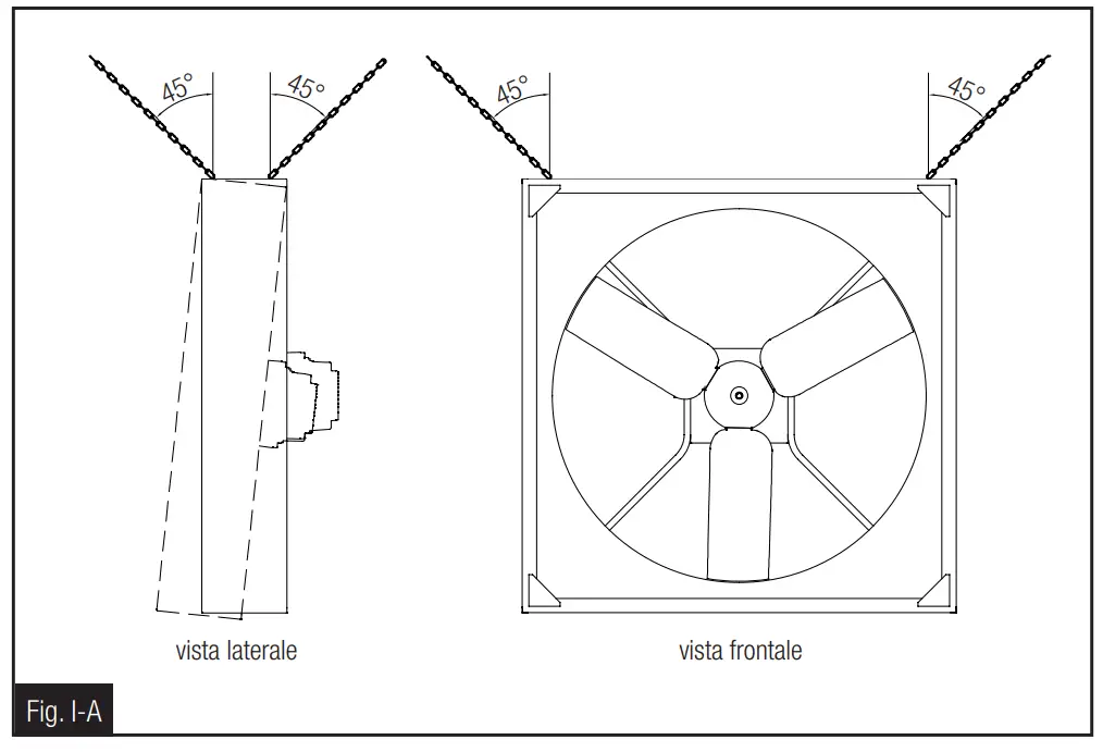
If the fan is tilted, the chains must be attached to the eyebolts previously mounted on the fixing points.
WIRING DIAGRAM
- Make sure that the mains supply to the unit is disconnected before performing any installation, service, maintance or electrical work!
- The installation and service of the unit and complete ventilation system must be performed by an authorized installer and in accordance with local rules and regulations.
- Fan must be earthed.
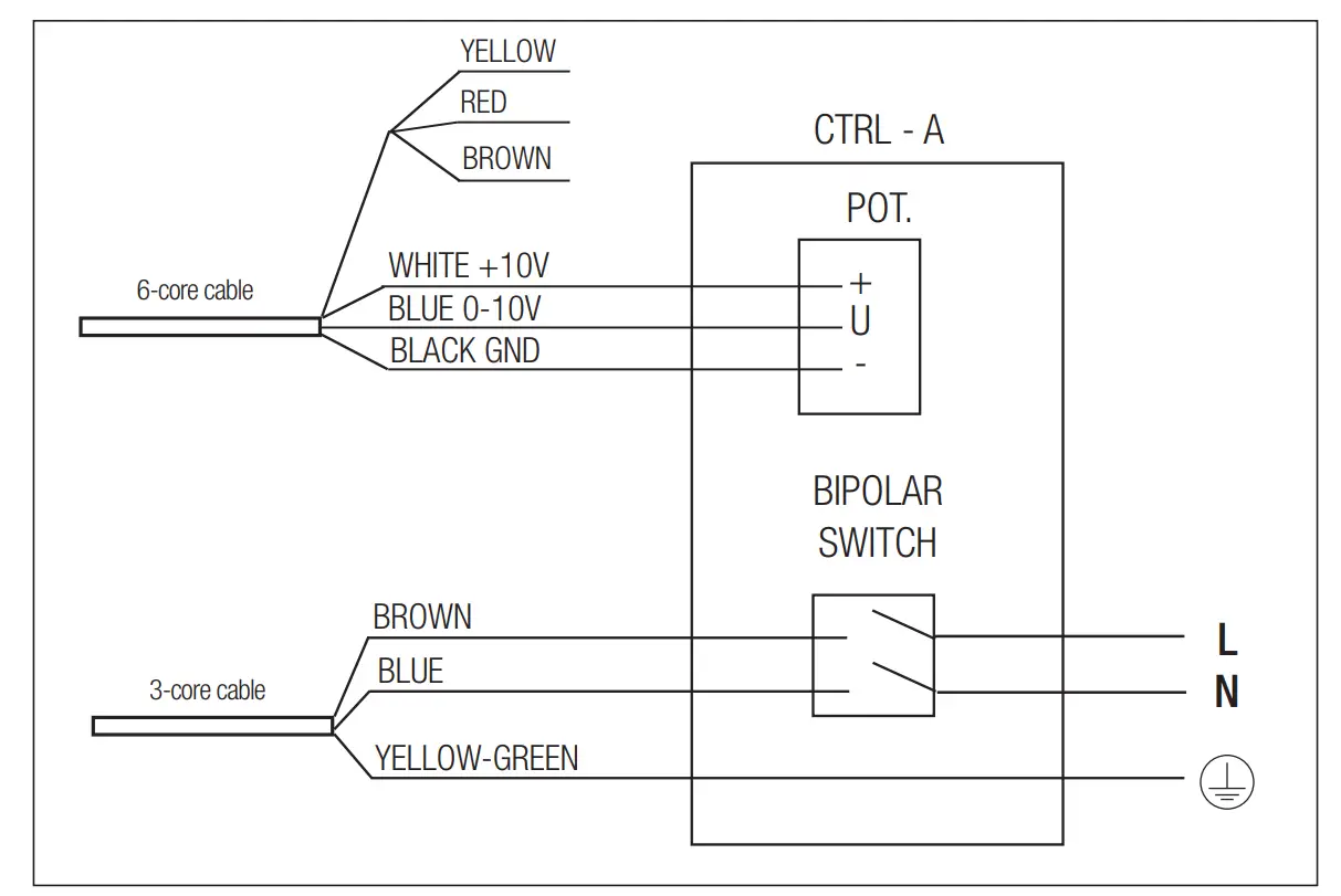
CTRL-A (accessory on request)
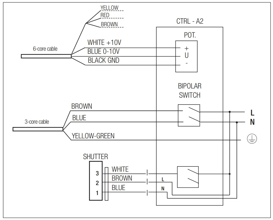
CTRL-A2 (accessory on request)
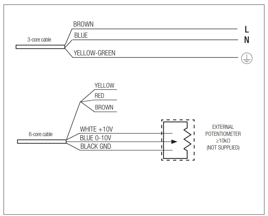
CONTROL WITH EXTERNAL POTENTIOMETER (not supplied)
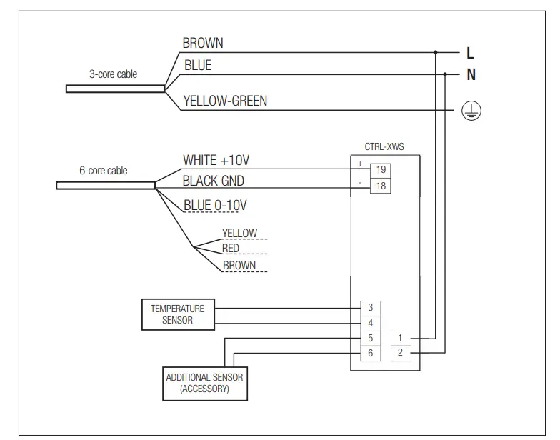
CTRL-XWS (accessory on request)
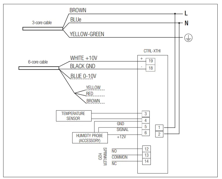
CTRL-XTHI (accessory on request)
DECLARATION OF CONFORMITY AND INCORPORATION
UE DECLARATION OF CONFORMITY/INCORPORATION
Manufacturer:
Via Mario Calderara 39/41 – 25018 Monti Chiari (BS) – ITALY
UE DECLARATION OF CONFORMITY
We herewith declare that the following range:
BRAND: AERAULIQA
MODELS:
AD1400A, AD1400B
on the basis of its design and construction as partly completed machines brought onto the market, is designed in compliance within relevant health and safety requirements of the following Directives:
2014/35/UE – Low Voltage Directive (LVD)
2014/30/UE – Electromagnetic Compatibility (EMC)
2009/125/EC – Energy Related Products (ErP)
in the event that alterations are made to the machinery without prior consent with the manufacturer, this declaration becomes invalid.
This declaration is issued under the sole responsibility of the manufacturer.
UE DECLARATION OF INCORPORATION
In accordance with the Machinery Directive 2006/42/EC
We herewith declare that the following range:
BRAND: AERAULIQA
MODELS:
AD1400A, AD1400B
on the basis of its design and construction of partly completed machines, is designed in compliance with the Essential Health and Safety Requirements (EHSRs) of ANNEX l, sections 1.1.2 (Safety integration), 1.1.5 (Handling), 1.4.1 (Protective devices), 1.5.1 (Electricity) of EC Machinery Directive 2006/42/EC.
The machinery is incomplete and must not be put into service until such time as the machinery which is partly complete is to be incorporated and has been assessed and declared in conformity with the provisions of the Machinery Directive 2006/42/EC.
We undertake to transmit, upon reasoned request by appropriate national authorities, relevant information on the partly completed machinery identified above.
Monti Chiari, 01/05/2022

CUSTOMERS SUPPORT
During installation, it is recommended to write the serial number of the unit in this manual and keep it safe for maintenance service.
Sede operativa/Warehouse-Offices: via Mario Calderara 39/41, 25018 Monti Chiari (Bs) – Sede legale/Registered office: via Mario Calderara 39/41, 25018 Montichiari (Bs)
C.F. e P.IVA/VAT 03369930981 – REA BS-528635 – Tel: +39 030 674681 – Fax: +39 030 6872149 – www.aerauliqa.it – www.aerauliqa.com – [email protected]
Aerauliqa S.r.l. reserves the right to modify/make improvements to products and/or this instruction manual at any time and without prior notice.